Running to the Stars

Concept:

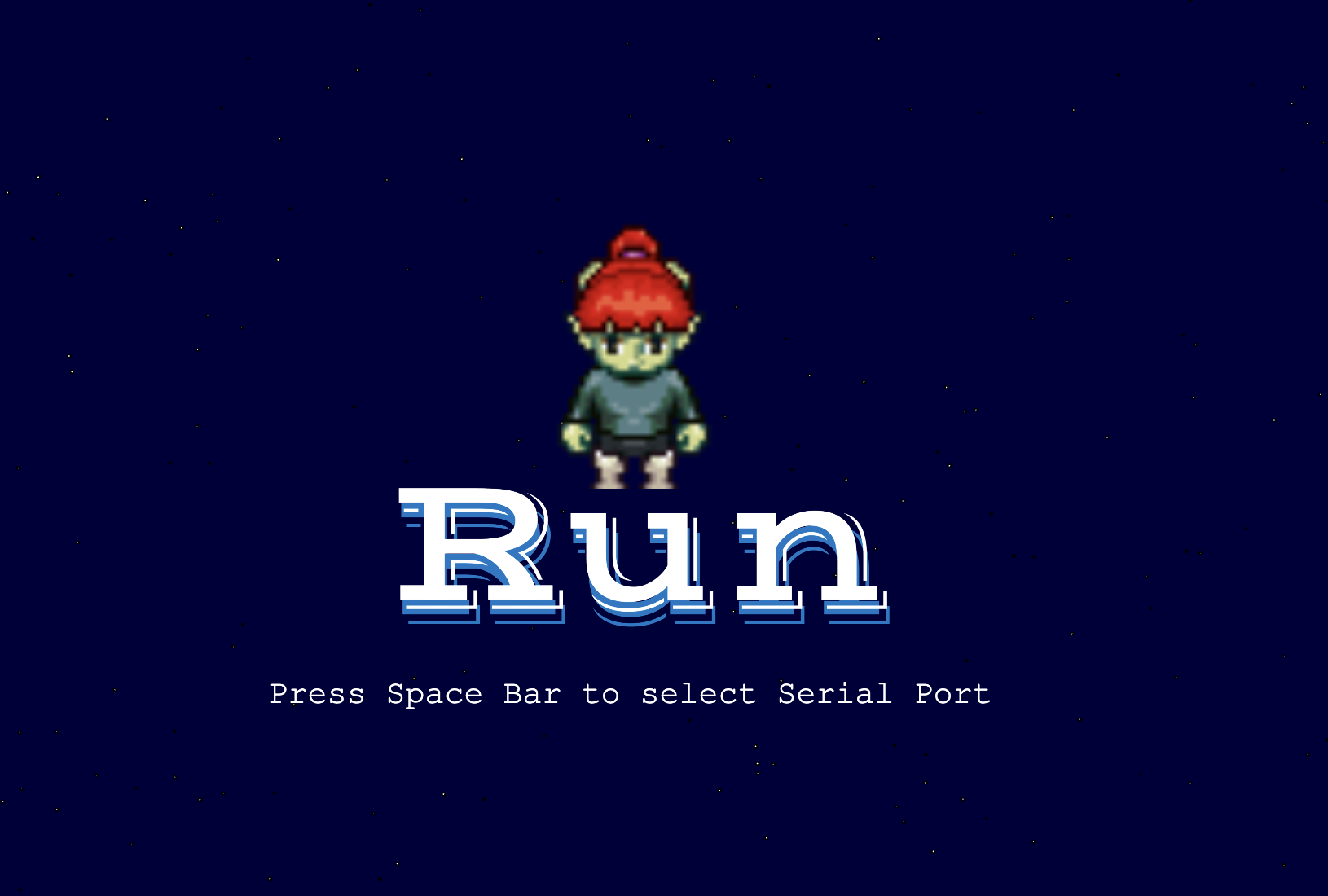
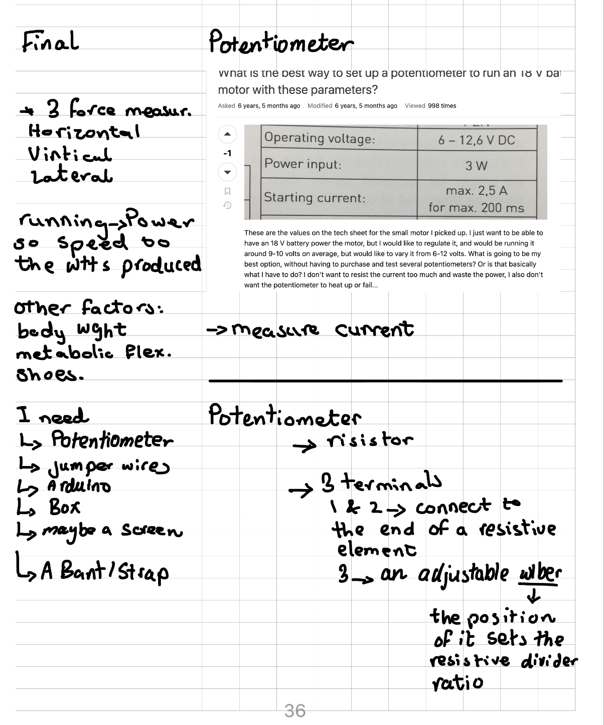
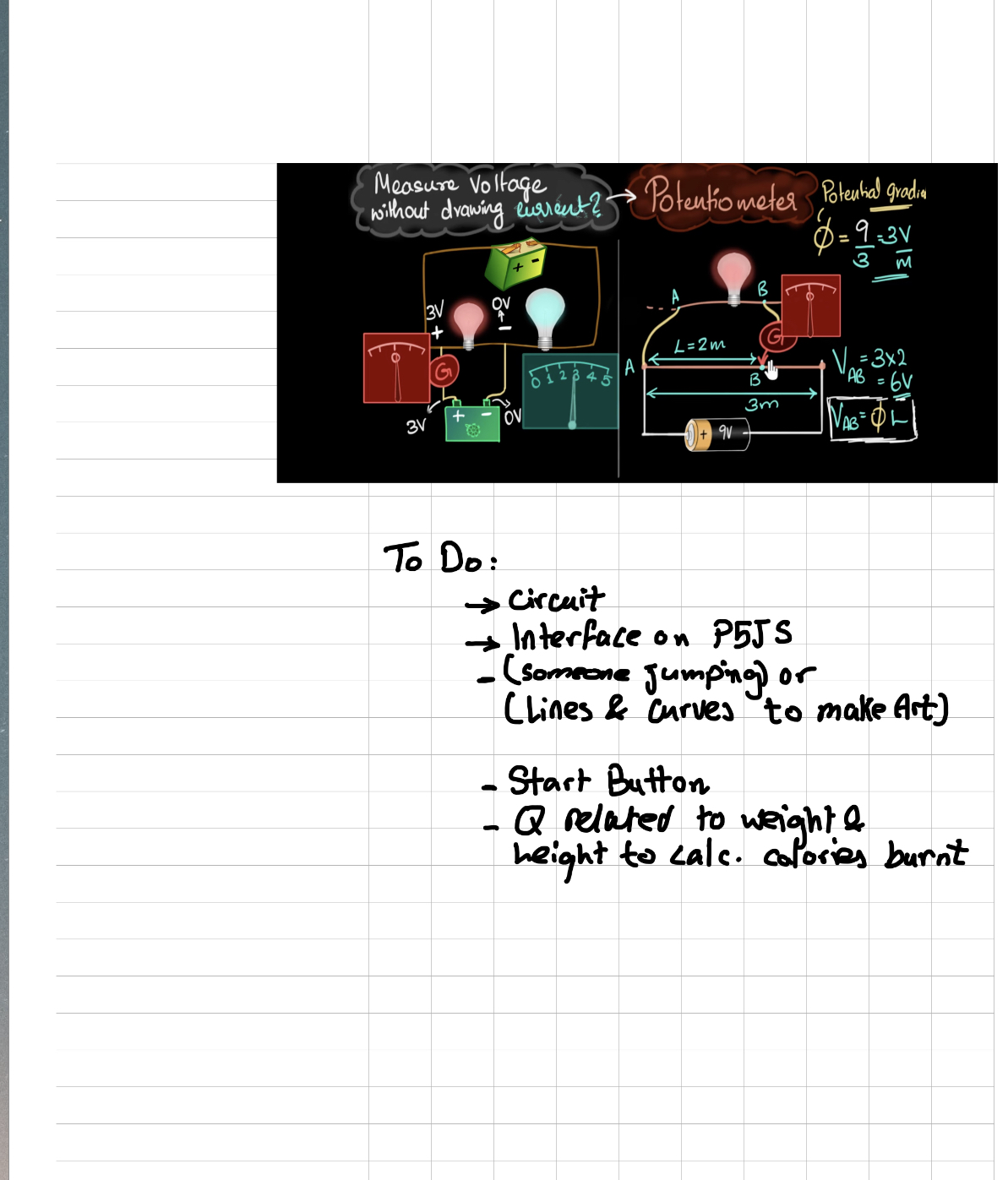
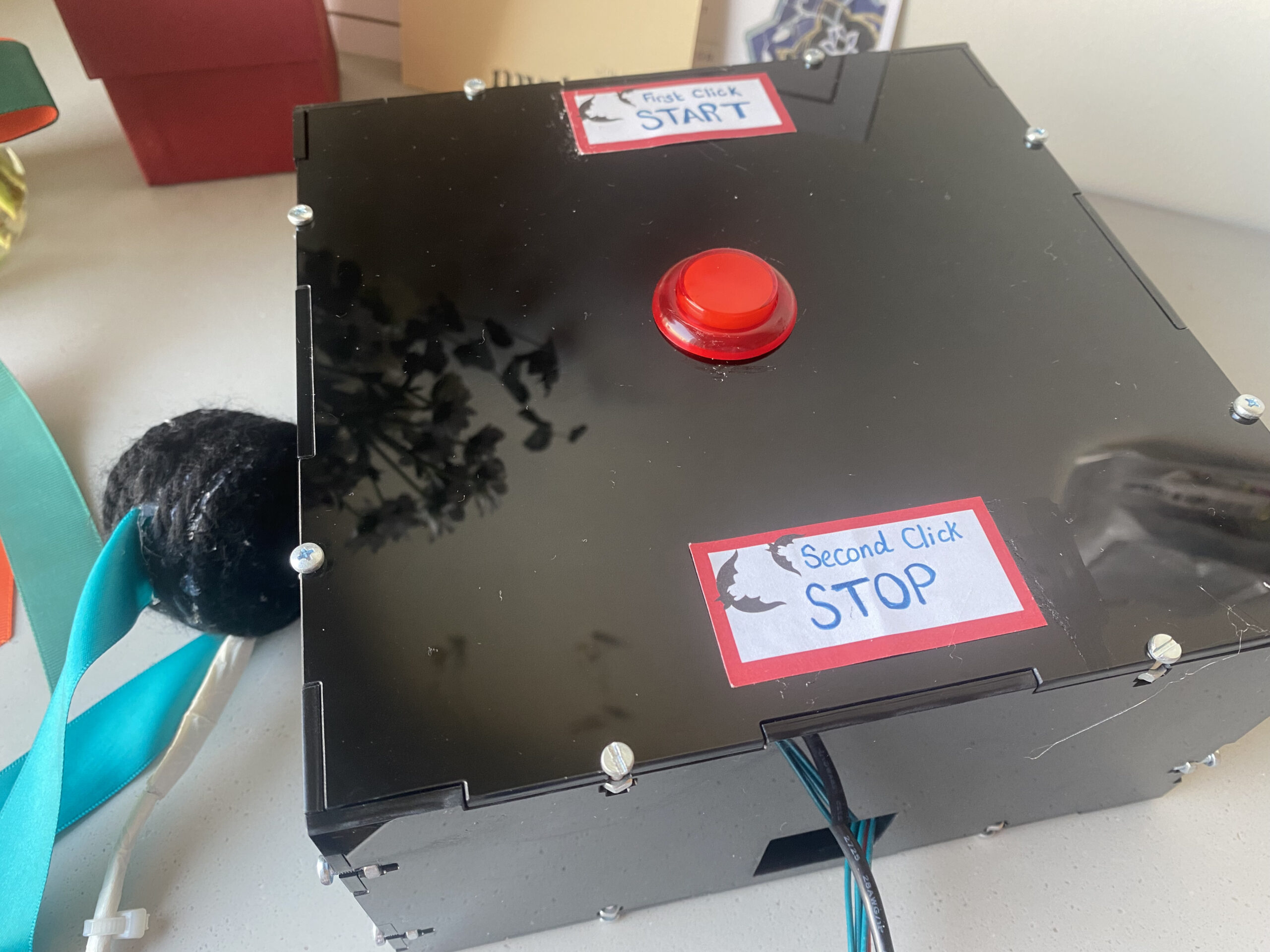
For my final project, I decided to make a running experience game with a timer. I had this idea so that people can exercise from home.  A person puts the accelerometer on his/her leg clicks the button to start the game and presses it again to end it. I wanted to go with a simple design and a specific purpose for this project.

Highlight and Process:

Different placements of the Accelerometer and data results

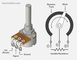
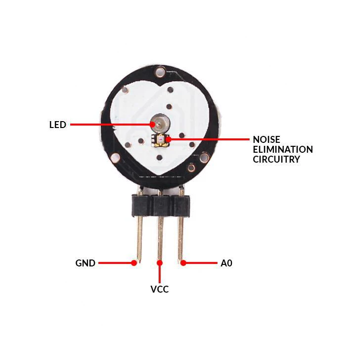
This project did not go as smoothly as I expected it to be. I had to try multiple sensors to see which one fits my concept best. I tried a potentiometer, an XYZ-axis accelerometer, and a Gyroscope Accelerometer. I had to research a lot about them and see what can be done.

circuit accelerometer
Arcade Switch with LED

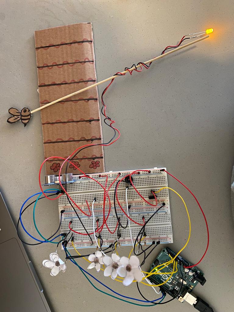
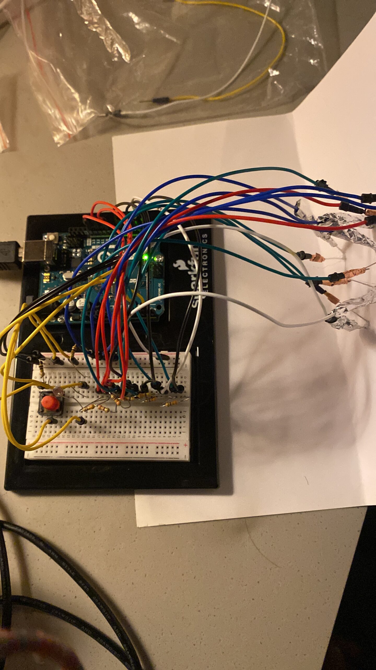
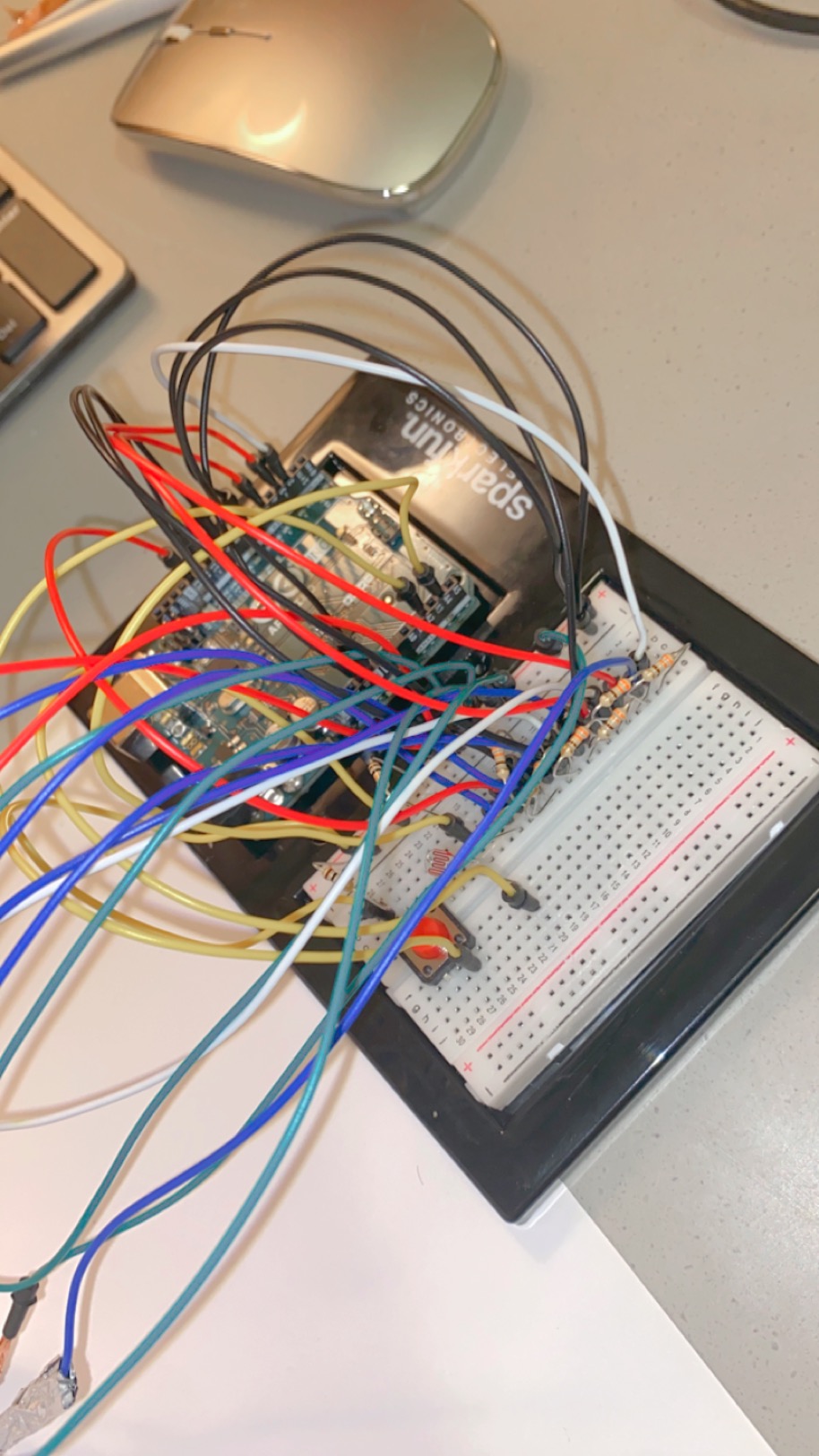
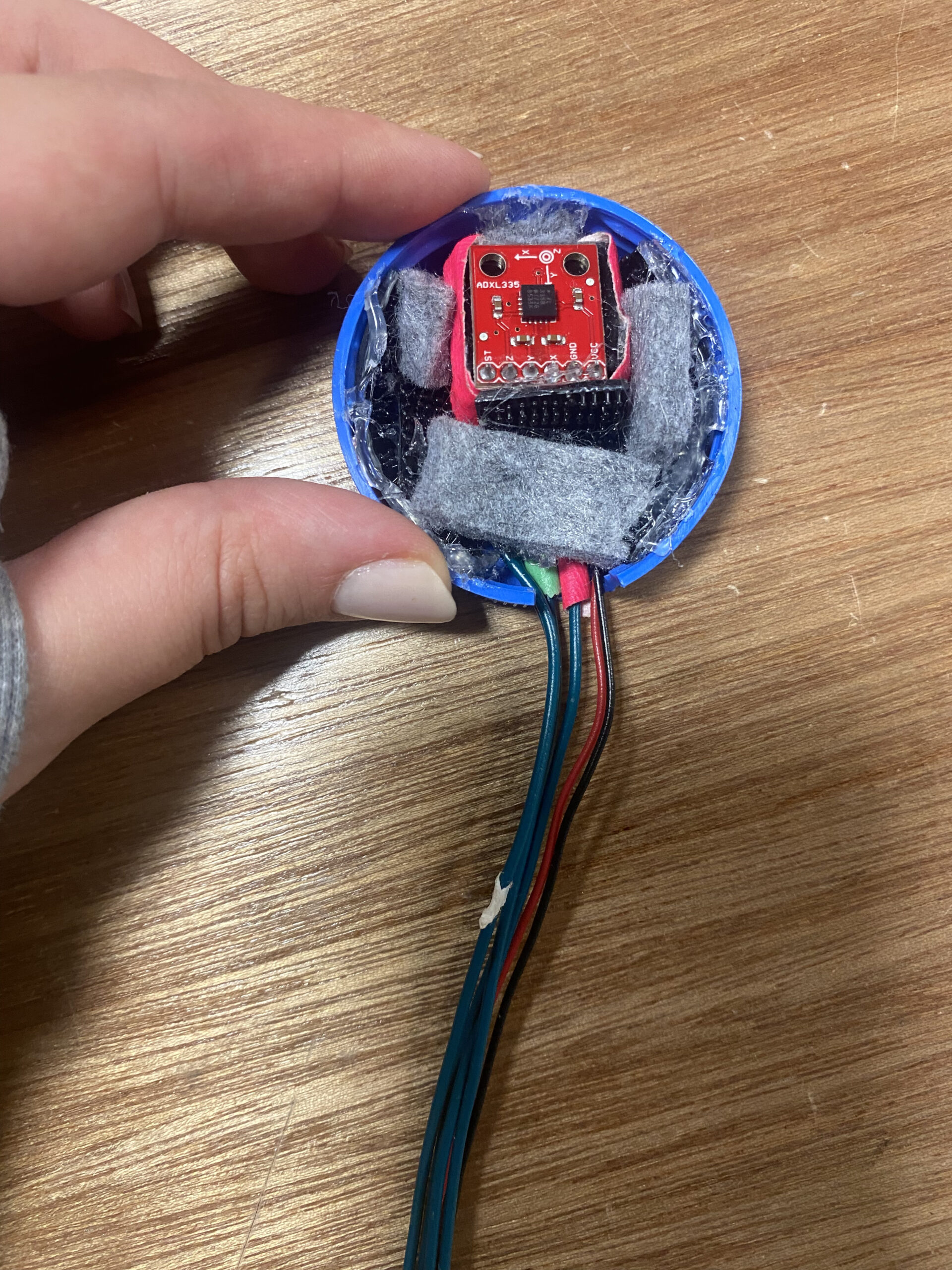
I decided to go on and use the ADXL335 Accelerometer. I read the documentation I found online for it. I have to say that figuring out the circuit was not the easiest thing either. I made the circuit maybe 5 times to get it right. I also decided to use the Arcade button with LED. I burned myself while soldering but I learned to be careful.

HandWritten-Documentation

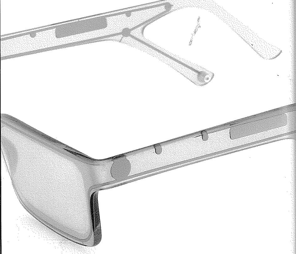
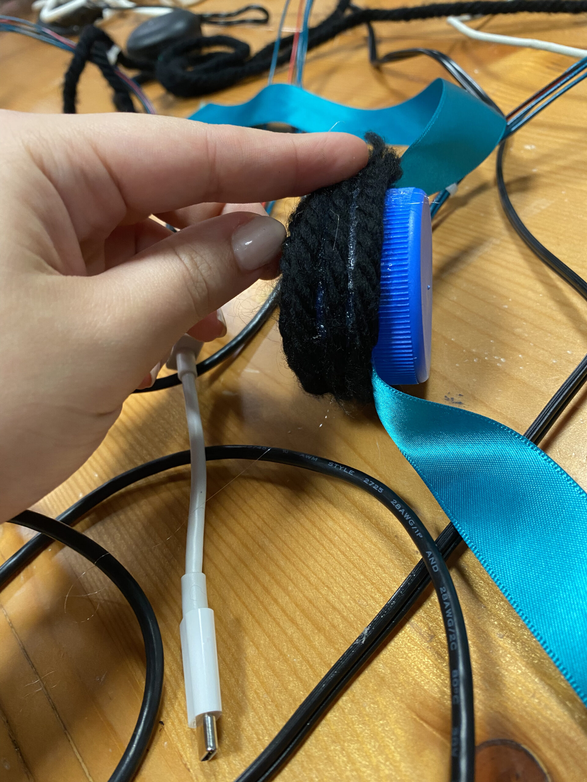
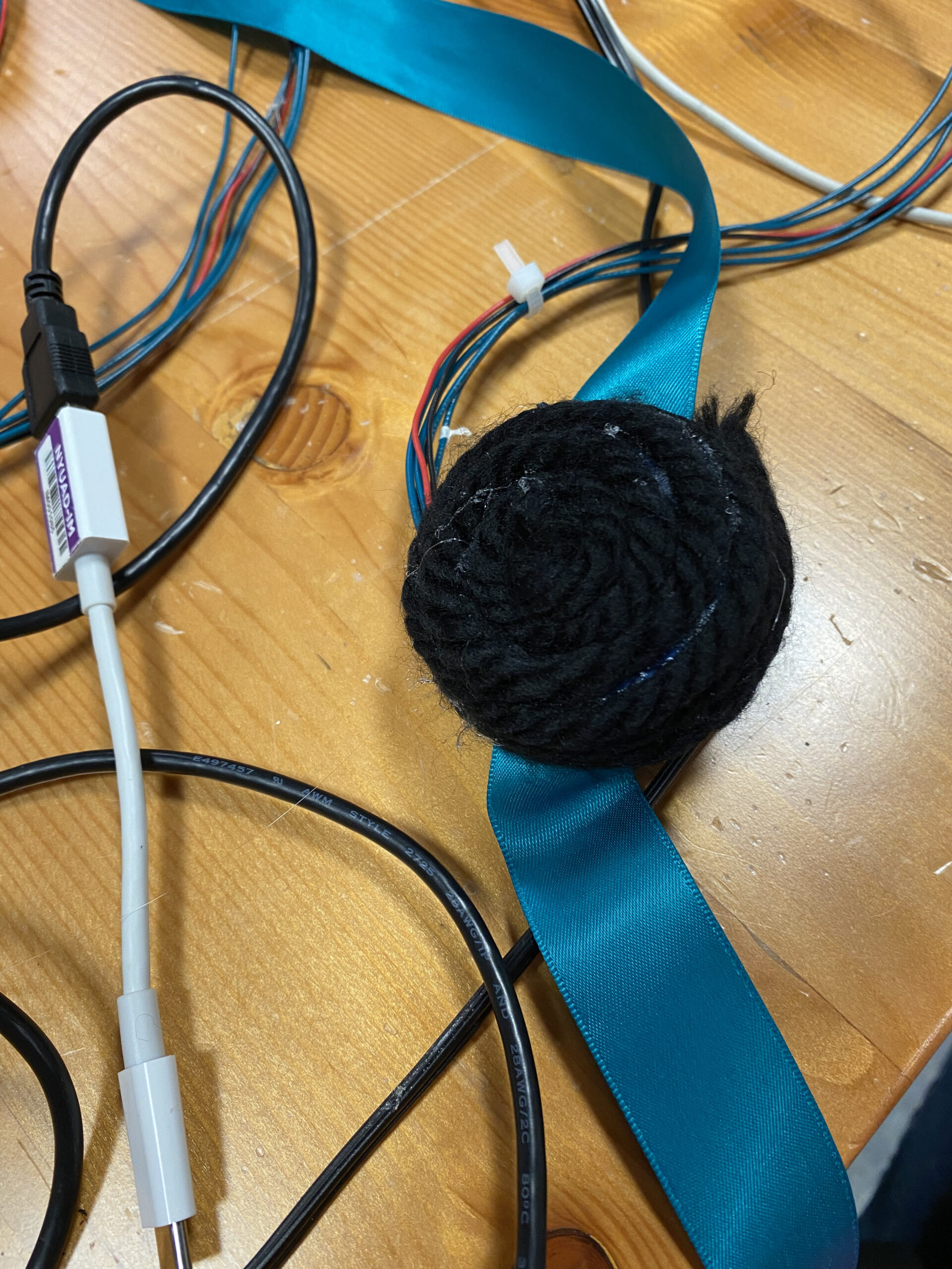
After figuring out the circuit and testing it with build-in examples, I moved on to designing the box and putting the accelerometer in a small container I made of two bottle caps. Cutting the box using the laser cutter was not smooth either as the laser cutter stopped working in the middle of cutting my box, and I had to redo it the next day. I made sure everything was in place and worked fine, then I moved to the code.

Video-> IM-final

I started with the code, and I found an example of how to convert the data we get from the accelerometer to acceleration. This was my starting point. I refined the code a little bit to serve the purpose of my project. Then I added different elements like the button and the serial communication. However, when I did that the code stopped working. It took me two days to figure out the problem as highlighted in the pdf file attached.

// variables for the sensor x, y, z axis
const int xInput = A0;
const int yInput = A1;
const int zInput = A2;


// initialize minimum and maximum Raw Ranges for each axis
int RawMin = 0;
int RawMax = 1023;

// Take multiple samples to reduce noise we take the average of these
const int sampleSize = 10;

// for the arcade button state and its led
// pinmodes and pin #
int button = 8;
int LED = 4;
//state of the button
int buttonState = 0;
int lastButtonState = 0;

int LED_state = 0;

// Take samples and return the average from the accelemeter --
// readAxis function takes the 10 samples from analog to digital converter of
// an Arduino and delivers the average value.
int ReadAxis(int axisPin) {
  long reading = 0;
  analogRead(axisPin);
  delay(1);
  for (int i = 0; i < sampleSize; i++) {
    reading += analogRead(axisPin);
  }
  return reading / sampleSize;
}


void setup() {
  analogReference(EXTERNAL);
  Serial.begin(9600);

  // We'll use the builtin LED as a status output.
  // We can't use the serial monitor since the serial connection is
  // used to communicate to p5js and only one application on the computer
  // can use a serial port at once.
  pinMode(LED_BUILTIN, OUTPUT);
  pinMode(button, INPUT_PULLUP);
  pinMode(LED, OUTPUT);

  // start the handshake
  // while (Serial.available() <= 0) {
  //   digitalWrite(LED_BUILTIN, HIGH);  // on/blink while waiting for serial data
  //   Serial.println("0,0");            // send a starting message
  //   delay(300);                       // wait 1/3 second
  //   digitalWrite(LED_BUILTIN, LOW);
  //   delay(50);
  // }
}

void loop() {
  //Read raw values
  int xRaw = ReadAxis(xInput);
  int yRaw = ReadAxis(yInput);
  int zRaw = ReadAxis(zInput);

  // Convert raw values to 'milli-Gs"
  long xScaled = map(xRaw, RawMin, RawMax, -3000, 3000);
  long yScaled = map(yRaw, RawMin, RawMax, -3000, 3000);
  long zScaled = map(zRaw, RawMin, RawMax, -3000, 3000);

  // re-scale to fractional Gs 1/1000 0f g
  float xAccel = xScaled / 1000.0;
  float yAccel = yScaled / 1000.0;
  float zAccel = zScaled / 1000.0;

  // wait for data from p5 before doing something
  // while (Serial.available()) {
  digitalWrite(LED_BUILTIN, HIGH);  // led on while receiving data

  buttonState = digitalRead(button);
  if (button != lastButtonState && lastButtonState == 1) {

    // delay helps in false pushes
    delay(50);
    if (buttonState == LOW) {

      if (digitalRead(LED) == 1) {
        LED_state = 0;
        // turn LED off
        digitalWrite(LED, LED_state);
      } else {
        LED_state = 1;
        digitalWrite(LED, LED_state);  // Turn on LED
      }
    }
  }
  lastButtonState = buttonState;

  // if (Serial.read() == '\n') {
  // send to p5js
  // Serial.print(xRaw);
  // Serial.print(", ");
  // Serial.print(yRaw);
  // Serial.print(", ");
  // Serial.print(zRaw);
  // Serial.print(" :: ");
  Serial.print(xAccel);
  Serial.print(',');
  Serial.print(yAccel);
  Serial.print(',');
  Serial.print(zAccel);
  Serial.print(',');
  Serial.println(LED_state);


  delay(200);
  // }

  digitalWrite(LED_BUILTIN, LOW);
}
// }


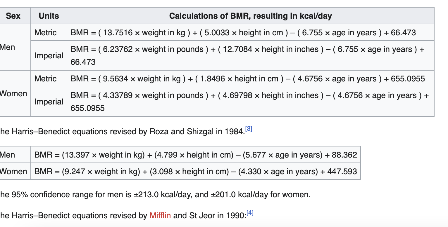
When I figured out the Arduino side. I began designing the interface of the project. I had to create different levels so that the users could switch from the start of the experience to the end and back again. I decided to use the LED state to do that. Meaning that when the LED state is 1 the experience starts and when it Is zero it ends.  In the States, I added what should happen. In the second state when the LED is 1, the timer starts and it starts looking through the sprite sheet at the rate of the Z-value multiplied by the time, which is linear speed. Unfortunately, I had to assume the physics to make it work and I am not sure how accurate it is. I have noticed that there is a little delay but I can’t figure out why. I think it is because P5js is a little slow.

P5js link ->https://editor.p5js.org/shn202/full/gOx6xjm6X

Reflection:

There is a lot more that can be done to this project. I will admit that I learned a lot implementing it and even though it is not as I expected it to be, I think with all the limitations and problems I faced it turned out to be good. In the future, I would like to make it more interactive with more preferences to it.  I feel time was a challenge in this project and that if we had more time it would have turned out better.

IM final

https://www.circuits-diy.com/how-adxl335-accelerometer-interface-with-arduino-uno/

https://www.tutorialspoint.com/vcc-and-vss-pins#:~:text=VCC%20(Voltage%20Common%20Collector)%20is,Supply)%20means%20ground%20or%20zero.

https://robu.in/accelerometer-sensor-arduino/

https://docs.arduino.cc/built-in-examples/sensors/ADXL3xx

https://lastminuteengineers.com/adxl335-accelerometer-arduino-tutorial/#:~:text=Wiring%20an%20ADXL335%20Accelerometer%20to%20an%20Arduino,-Now%20that%20we&text=Connections%20are%20pretty%20simple.,A0%2C%20A1%2C%20and%20A2.

https://www.youtube.com/watch?v=wTfSfhjhAU0

https://docs.arduino.cc/software/ide-v1/tutorials/installing-libraries

https://forum.pololu.com/t/l3gd20-gyro-unable-to-get-sample-arduino-code-working/5146

https://howtomechatronics.com/tutorials/arduino/how-to-track-orientation-with-arduino-and-adxl345-accelerometer/

https://www.youtube.com/watch?v=KMhbV1p3MWk&t=333s

https://www.youtube.com/watch?v=-QY0jN3gtgs&t=301s

https://en.wikipedia.org/wiki/Potentiometer

https://forum.arduino.cc/t/determine-speed-from-hollow-shaft-potentiometer/143502

https://www.khanacademy.org/science/in-in-class-12th-physics-india/in-in-current-electricity/x51bd77206da864f3:potentiometers/v/potentiometer-calculating-internal-resistance-of-a-cell

https://github.com/pololu/l3g-arduino

Final Project

Concept: 

For the final project, I decided to go with the running experience. For this project, I will use a potentiometer, wires, and a band to create a circuit that will receive data from the user (motion) and translate it into a visible visual to P5js. 

I have been trying to collect data and learn more about the potentiometer and how to make the project a reality. 

Arduino Design: 

For the circuit, I will connect one end of the potentiometer to 5v, another to GND, and the third to an analog pin and a band attached to the user.

In this case, the input is the Potentiometer Data, which presents the running speed, and the output will transfer the values to the computer for further manipulation. 

I will also try to make the band and the potentiometer appealing to the user and maximize safety while using. 

P5js Design:

I have to create a start button for users to start the experience. Then, I have to constantly update the 

canvas with the speed obtained from Arduino. Finally, I have to use the data to estimate the calories burned probably using the Harris-Benedict equation. 

https://www.omnicalculator.com/health/bmr-harris-benedict-equation

P5 will receive data from Arduino. Then it will visually display the results in real-time. I am still not sure if I will make a character that would run at the same speed as the user, or an object, or maybe translate the data into an artwork for the user to have. 

After the person is done they will have the amount of calories burnt during the the running time. This way the project would be helpful but also fun for the user. 

Final ideas


I am still not sure what to do for my final project I have three different ideas and I am not sure which one to pick.

Idea 1:

I am thinking of doing a PS4-like controller with a car race on the screen. It would have some audio effects and a trick to win or lose. I want to do it so that 2 people might be able to race at the same time. However, I am not sure how and if I will be able to do it. It seems like a cool idea but I am a little overwhelmed by how it will go. It can either work fine or go the other way around.

Idea 2:

I am thinking of having a screen and a small area where people can run in place but seem as if they are running on a track. Maybe the speed of the person running is controlled by the heart rate. Then maybe I would do some research to see how many calories the person burned at a specific time their weight. It seems an interesting idea. However, it is also challenging and how I visualize it is that it is somehow immersive so that the person only focuses on the running and not what is going on around them.

Ideas 3:

A small physical car and a controller.  I might make a car that moves on a track using a controller similar to kids’ car toys. However, I am trying to think of a twist or a way to make It more engaging. I am not sure until now how to do so.

Design Meets Disability


I think the reading was interesting it communicated the importance of design to disabilities and how it opens a new possibility to re-invent these pieces as fashion and not only for medical purposes. I enjoyed the part about glasses because it reminded me of the times when I would go shopping with my mom and I always try many on before picking one that suits me. I can not imagine a time when glasses were not stylized. Similarly, I think there is a sense of struggle when comes to designing things for disability, I will argue that maybe because the person designing these pieces is not disabled himself/herself which would be a problem because the designer would not know what the people who he/she is designing for wants. I think part of the design process is to know the consumers well. Their opinion, their style, and what they want. However, the reading lacked that part. Especially when it comes to design Ear- Wear and different body limbs.

It is good to design products that are more inclusive and toward the disabled like clickable audio buttons, or products that have braille on them. Further, how do we design products that can compensate people who lack some limps? Do we incorporate different limps to our design too or do we make our products useable in different ways but with the same effect? I do not think that the radio example is that inclusive it might be to a degree but I think it could be more inclusive if the designers would allow users to control it with voice, or even control it with brail and then would also have a small screen that writes whatever is being displayed in the radio

3 Examples

Process:

For this assignment, we had to finish the three in-class examples that connect p5js and Arduino. In the beginning, I thought I understood the code and the connection but then I realized that I did not fully understand it. So I decided to review it line by line and try to understand the communication between Arduino and P5js.

Then Yupu and I decided to work together on these three examples we divided them so that he worked on the first one I worked on the second and we both worked on the third together. We helped each other debug the code and figure out how to implement it together. Honestly, this process of debugging helped me understand the communication between the two (P5js and Arduino) better.

Example 1: Circle Moving


// Week 11.2 Serial port - Light sensor, ball and light example 1 


int leftLedPin = 7;
int rightLedPin = 4;


void setup() {
 // Start serial communication so we can send data
 // over the USB connection to our p5js sketch
 Serial.begin(9600);


 // We'll use the builtin LED as a status output.
 // We can't use the serial monitor since the serial connection is
 // used to communicate to p5js and only one application on the computer
 // can use a serial port at once.
 pinMode(LED_BUILTIN, OUTPUT);


 // Outputs on these pins
 pinMode(leftLedPin, OUTPUT);
 pinMode(rightLedPin, OUTPUT);


 // Blink them so we can check the wiring
 digitalWrite(leftLedPin, HIGH);
 digitalWrite(rightLedPin, HIGH);
 delay(200);
 digitalWrite(leftLedPin, LOW);
 digitalWrite(rightLedPin, LOW);


 // start the handshake
  while (Serial.available() <= 0) {
    digitalWrite(LED_BUILTIN, HIGH);  // on/blink while waiting for serial data
      Serial.println("0,0");            // send a starting message
    delay(300);                       // wait 1/3 second
    digitalWrite(LED_BUILTIN, LOW);
    delay(50);
  }
}


void loop() {
 // wait for data from p5 before doing something
 while (Serial.available()) {
   digitalWrite(LED_BUILTIN, HIGH);  // led on while receiving data


   if (Serial.read() == '\n') {


     int sensor = analogRead(A1);  //potentiometer
     Serial.println(sensor);
   }
 }
 digitalWrite(LED_BUILTIN, LOW);
}


Example 2: LED Brightness

// Week 11.2 Example LED brightness


int leftLedPin = 6;

void setup() {
  // Start serial communication so we can send data
  // over the USB connection to our p5js sketch
  Serial.begin(9600);


  // We'll use the builtin LED as a status output.
  // We can't use the serial monitor since the serial connection is
  // used to communicate to p5js and only one application on the computer
  // can use a serial port at once.
  pinMode(LED_BUILTIN, OUTPUT);

  // Outputs on these pins
  pinMode(leftLedPin, OUTPUT);

  // start the handshake
  while (Serial.available() <= 0) {
    digitalWrite(LED_BUILTIN, HIGH);  // on/blink while waiting for serial data
    Serial.println("0,0");            // send a starting message
    delay(200);                       // wait 1/3 second
    digitalWrite(LED_BUILTIN, LOW);
    delay(200);
  }
}


void loop() {
  // wait for data from p5 before doing something
  while (Serial.available()) {
    digitalWrite(LED_BUILTIN, HIGH);  // led on while receiving data

    int brightness = Serial.parseInt();
    analogWrite(leftLedPin, brightness);
    if (Serial.read() == '\n') {
      Serial.println("0,0");
    }
  }
  digitalWrite(LED_BUILTIN, LOW);
}


Example 3:  Gravity, Ball, and LED

// week 11 example 3 sensor analg and digital light and abouncing ball 

int leftLedPin = 7;
int rightLedPin = 4;


void setup() {
 // Start serial communication so we can send data
 // over the USB connection to our p5js sketch
 Serial.begin(9600);


 // We'll use the builtin LED as a status output.
 // We can't use the serial monitor since the serial connection is
 // used to communicate to p5js and only one application on the computer
 // can use a serial port at once.
 pinMode(LED_BUILTIN, OUTPUT);


 // Outputs on these pins
 pinMode(leftLedPin, OUTPUT);
 pinMode(rightLedPin, OUTPUT);


 // Blink them so we can check the wiring
 digitalWrite(leftLedPin, HIGH);
 digitalWrite(rightLedPin, HIGH);
 delay(200);
 digitalWrite(leftLedPin, LOW);
 digitalWrite(rightLedPin, LOW);


 // start the handshake
  while (Serial.available() <= 0) {
    digitalWrite(LED_BUILTIN, HIGH);  // on/blink while waiting for serial data
    Serial.println("0,0");            // send a starting message
    delay(300);                       // wait 1/3 second
    digitalWrite(LED_BUILTIN, LOW);
    delay(50);
  }
}


void loop() {
 // wait for data from p5 before doing something
 while (Serial.available()) {
   digitalWrite(LED_BUILTIN, HIGH);  // led on while receiving data


   int LED_STATE = Serial.parseInt();
   //int right = Serial.parseInt();
   if (Serial.read() == '\n') {
     digitalWrite(rightLedPin, LED_STATE);
     int sensor2 = analogRead(A1);
     delay(5);
     Serial.print(sensor2);
     Serial.print(',');
     Serial.println('Y');
   }
 }
 digitalWrite(LED_BUILTIN, LOW);
}


Music Instrument

Concept:

I think it was a challenge for us to find an idea for this project. Alex and I shared some videos of cool musical instruments with one another. We also tried to brainstorm some ideas and think of how to do it. We wanted to do something interesting, and creative. After a series of discussions, we finally decided to make a flower and bee instrument. This instrument plays different sounds if the bee comes to a flower, or if sunlight is pointed at a flower. Also, it plays sound when the bee is going to the flower. We did this by making a circuit that had a toggle switch, an LED, four light sensors, one distance sensor, and a piezo buzzer. Would it be cool if one could hear sounds emitted by a flower under different conditions?

Our instrument makes different notes with the interaction between the flower, bee, and light, which I like to think of as a musical narrative that delves into the natural world.

Highlight:

 We began by assembling the circuit and making the flower, bees, and light source.

It was confusing to make the circuit, but it worked out fine in the end. We decided to add a toggle switch to move from the distance sensor to the light sensor, this enhanced the user experience by allowing them to transition between the distance sensor and the light sensors. The light sensor and the distance sensor add different interactive experiences for the user, which I think engages them more.

#include "pitches.h"

const int BUZZER = 8;
const int ECHO_PIN = 9;
const int TRIG_PIN = 10;
const int FLOWER1 = A0;
const int FLOWER2 = A1;
const int FLOWER3 = A2;
const int FLOWER4 = A3;
const int SWITCH = A5;
int flowerSound = 0;
int LED=2;
long duration = 100;

int DARK_THR = 600;

void setup() {
  // initialize serial communication at 9600 bits per second:
  Serial.begin(9600);
  pinMode(FLOWER1, INPUT);
  pinMode(FLOWER2, INPUT);
  pinMode(FLOWER3, INPUT);
  pinMode(FLOWER4, INPUT);
  pinMode(BUZZER, OUTPUT);  
  pinMode(ECHO_PIN, INPUT);    // echo pin measure the duration of pulses coming back from the distance sensor
  pinMode(TRIG_PIN, OUTPUT);   // trigger pin output pulses of electricity
  pinMode(LED,OUTPUT);
}

void loop() {
  digitalWrite(LED,HIGH);
  int flower1 = analogRead(FLOWER1);
  delay(1);  // delay in between reads for stability
  int flower2 = analogRead(FLOWER2);
  delay(1);  // delay in between reads for stability
  int flower3 = analogRead(FLOWER3);
  delay(1);  // delay in between reads for stability
  int flower4 = analogRead(FLOWER4);
  delay(1);  // delay in between reads for stability
  int switchOn = digitalRead(SWITCH);
  delay(1);  // delay in between reads for stability

  // Serial.println(switchOn);  ///debugging

  if (switchOn) {
    //dark sensor = lower notes
    if (flower1 <= DARK_THR) {
      tone(BUZZER, NOTE_C3, duration);
    } else if (flower2 <= DARK_THR) {
      tone(BUZZER, NOTE_D3, duration);
    } else if (flower3 <= DARK_THR) {
      tone(BUZZER, NOTE_E3, duration);
    } else if (flower4 <= DARK_THR) {
      tone(BUZZER, NOTE_F3, duration);

    //bright sensor = higher notes
    } else if (flower1 >= 850) {
      tone(BUZZER, NOTE_G3, duration);
    } else if (flower2 >= 850) {
      tone(BUZZER, NOTE_A3, duration);
    } else if (flower3 >= 850) {
      tone(BUZZER, NOTE_B3, duration);
    } else if (flower4 >= 850) {
      tone(BUZZER, NOTE_C4, duration);
    } else {         
      noTone(BUZZER);
    }
  } else { // if switch is changed to distance sensor
    int distance = getDistance();
    Serial.println(distance);
    if (1 < distance && distance < 3) {
      tone(BUZZER, NOTE_C4);
    } else if (3 < distance && distance < 6) {
      tone(BUZZER, NOTE_D4);
    } else if (6 < distance && distance < 9) {
      tone(BUZZER, NOTE_E4);
    } else if (9 < distance && distance < 12) {
      tone(BUZZER, NOTE_F4);
    } else if (12 < distance && distance < 15) {
      tone(BUZZER, NOTE_G4);
    } else if (15 < distance && distance < 18) {
      tone(BUZZER, NOTE_A4);
    } else if (18 < distance && distance < 21) {
      tone(BUZZER, NOTE_B4);
    } else {
      noTone(BUZZER);
    }
  }
}

float getDistance() {
  float echoTime;                   //variable to store the time it takes for a ping to bounce off an object
  float calculatedDistance;         //variable to store the distance calculated from the echo time

  //send out an ultrasonic pulse that's 10ms long
  digitalWrite(TRIG_PIN, HIGH);
  delayMicroseconds(10);
  digitalWrite(TRIG_PIN, LOW);

  echoTime = pulseIn(ECHO_PIN, HIGH);      //pulsein command to see how long it takes for pulse to bounce back to sensor
  calculatedDistance = echoTime / 55.2;    //calculate  distance of object that reflected the pulse in cm 
  return calculatedDistance;  
}


The code was simple, we created a nested if condition so that when the switch is on the light sensors (the flowers) would play different notes. The notes change in pitch from low to high depending on whether the bee is on the flower of the light source. Then when the switch is off we move to the distance sensor where the bee moves displaying different sounds. These notes are played with a difference of 3cm in distance. For the distance sensor, we play a whole octave of notes.


 Reflection and Future Improvements:

 I enjoyed making this assignment, but I believe there is room for improvement. There is much more that can be done and improved so that the sound is clearer, and the instrument is more interesting. It would be cool if it were a dual-player instrument, which means that the distance sensor and the light sensor play the sounds at the same time. It is a little more complicated to do and would need more time. On the aesthetics aspect, canceling all the wires in a box would be neater, and safer for users, thus providing an appealing look. I believe there is space to enhance this project in terms of functionality and look; however, this project was a challenge technically but sparked our imagination.

Week 10 – Response

The Future of Interaction Design  and Responses: A Brief Rant on the Future of Interaction Design:

The rant is about a problem in interaction designs now. They are not tangible interfaces, dynamic materials, and/or haptic. Human Capabilities were the main concern of the author. I think humans’ capabilities are daffier. As much as it was an interesting read as much as it is not inclusive. There are a lot of responsibilities and an interactive designer needs to keep in mind in terms of inclusivity. I think accessibility is a big concern. I agree that capabilities like our hands and fingers can do a lot of things and influence our futures and how they are incredible but this also made me think of those who do not have them. What should an interaction designer do? How can we help? How should we compensate?  I do not know the answer, but I hope one day I will.

I like the part when he/she started to talk about choices, and we chose what to do and how to interact. I agree and I think as interactive designers we should choose to have a responsibility to make our designs inclusive as much as we can.

I think there is a lot to be done in research regarding tangible interfaces, dynamic materials, and haptic because they are somehow inadequate. Thus, I wonder what would be a dynamic medium for keyboards.

Even though he is trying to challenge us to create designs that take advantage of our capabilities I think there should be a balance between that and the idea that capabilities might not always be equal.


Week 9 Sensors – Christmas Tree

Concept:

For this assignment, we had to get information from an analog and a digital sensor and control 2 LEDs, one with the analog and one with the digital. Since it is almost Christmas season, I wanted to create a Christmas tree lit by a light sensor and a switch separately. I really like this time of the year because it is special in my hometown. It is all about family and friends gatherings, rainy days, meaningful conversations with delicious food, and an end-of-year celebration.

Highlight:

Reviewing the lecture notes and my notes was key in constructing this assignment. I started by drawing the tree, coloring it, and marking where I wanted the LEDs to go. I had to glue things in place because the paper was not strong enough to handle all the LEDs and wires.

I was a little scared of assembling the circuit in the wrong way and creating a shot, but it worked out well. However, I had to figure out how to deal with many things to make this project work. For instance,  I  had to figure out how to make the LED anode longer. To fix this problem, I  decided to use wires and attach them to the anode and the board instead of attaching the LEDs directly to the board. It was frustrating to attach the wires to the LEDs especially to keep them in place. To distinguish between the positive and negative anodes of the LED I used foil for one and copper tape for the other. Doing so made it less confusing to attach them to the board. I had some doubts about whether the circuit was correct or not so I re-assembled them multiple times to make sure I made it correctly. Attaching the switch and the light sensor was easier. Even though I made two codes one for the switch and the other for the light sensors, on the board they both share the same GND and the 5V.

The code is like to what we did in class. I tried to figure out how to add all Pins in one line of code but I could not figure out how,

Light Sensor:

// the setup routine runs once when you press reset:
void setup() {
  // initialize serial communication at 9600 bits per second:
  Serial.begin(9600);
  pinMode(13, OUTPUT);
  pinMode(11, OUTPUT);
  pinMode(9, OUTPUT);
  pinMode(7, OUTPUT);
  pinMode(5, OUTPUT);
  pinMode(3, OUTPUT);
  pinMode(2, OUTPUT);
}

// the loop routine runs over and over again forever:
void loop() {
  // read the input on analog pin 0:
  int sensorValue = analogRead(A4);
  if (sensorValue > 255) {
    digitalWrite(13, LOW);
    digitalWrite(11, LOW);
    digitalWrite(9, LOW);
    digitalWrite(7, LOW);
    digitalWrite(5, LOW);
    digitalWrite(3, LOW);
    digitalWrite(2, LOW);
    delay(1000);  // turn the LED off by making the voltage LOW
  }
  // wait for 30 milliseconds to see the dimming effect
  else {
    digitalWrite(13, HIGH);
    digitalWrite(11, HIGH);
    digitalWrite(9, HIGH);
    digitalWrite(7, HIGH);
    digitalWrite(5, HIGH);
    digitalWrite(3, HIGH);
    digitalWrite(2, HIGH);
  }
}

Switch :

// digital pin 2 has a pushbutton attached to it. Give it a name:
int pushButton = A2;

// the setup routine runs once when you press reset:
void setup() {
  // initialize serial communication at 9600 bits per second:
  Serial.begin(9600);
  // make the pushbutton's pin an input:
  pinMode(pushButton, INPUT);
  pinMode(13, OUTPUT);
  pinMode(11, OUTPUT);
  pinMode(9, OUTPUT);
  pinMode(7, OUTPUT);
  pinMode(5, OUTPUT);
  pinMode(3, OUTPUT);
  pinMode(2, OUTPUT);
}

// the loop routine runs over and over again forever:
void loop() {
  // read the input pin:
  int buttonState = digitalRead(pushButton);
  // print out the state of the button:
 if (buttonState==1) {
  digitalWrite(13, HIGH);
    digitalWrite(11, HIGH);
    digitalWrite(9, HIGH);
    digitalWrite(7, HIGH);
    digitalWrite(5, HIGH);
    digitalWrite(3, HIGH);
    digitalWrite(2, HIGH);
  
    // turn the LED off by making the voltage LOW
  }
  // wait for 30 milliseconds to see the dimming effect
  else {
      digitalWrite(13, LOW);
    digitalWrite(11, LOW);
    digitalWrite(9, LOW);
    digitalWrite(7, LOW);
    digitalWrite(5, LOW);
    digitalWrite(3, LOW);
    digitalWrite(2, LOW);
    
    
  }
}


Reflection and future improvements:

Trusting the process was a huge reason why this project worked. It is not complicated, but it needs a lot of focus. In the future, I want to make it more presentable and neater. I want to also find a way where both the sensors work together in the same code.

Merry Christmas!

Week 9 – Reading Response

Making Interactive Art: Set the Stage, Then Shut Up and Listen

I agree that art should be open to interpretation. I think interactive art requires time from the artist and is open to change and manipulation in response to the user’s experience. The first time an artist does an interactive art it might not go as planned especially if he/she does not add instructions, but that is ok because they would learn and start up conversations with the viewers and redefine it to make it work better. I believe a good interactive piece is self-explanatory and does what the artist expects at least 50/60% of the time. However, some interactive art pieces are made to be experienced differently.

I liked the part about listening to the audience while they are experiencing the piece because this starts interesting conversations and may inspire new ideas. I agree that an interactive artist is like a director. He/she proposes materials and interactions to the audience and then they can interpret it in ways that express themselves and the artist too.

Physical Computing’s Greatest Hits (and Misses)

I agree that recreating things can lead to further developments. There is a book I once read called “Steal Like an Artist” and it talks about how everything we do is inspired by things that already exist. A lot of technological advances came to exist because they were recreating something but found a new thing on the way. If we think of coding, for example, we would have not been so advanced and creative if we kept figuring out the logic that is already there. Instead, we take the pre-existing logic and then add to it and develop it to be better.

I enjoyed the piece on Floor Pads because it seems simple and fun. I also think that the meditation helper is cool. As a person who dies yoga I think is a really good way to focus and try to maintain your inner balance at home. However, I am not sure how it “reacts to your state of mind” because it might not be accurate. Thus, it’s pretty cool if it can be accurate.


Safety Switch

Concept:

For this assignment, I wanted to take the chance to get used to using Arduino, circuits, and everything we learned in class. At first, I was intimidated by the kit we had because I did not know what anything was or how it worked.

It was not easy to get an idea for this assignment mainly because I do not know yet the many things I can do with Arduino. For this assignment, I wanted to do something useful especially when it comes to kids.  As scissors can cause damage when kids touch them, I decided to create a switch that turns on when the scissors are opened or touched. It is a simple idea and the main concept behind it is to learn more about Arduino.

Highlight:

IMAssignment

I always start with research. I personally can start doing something if I am not sure if I fully understand its different components and how it really works.  As you can see in the file attached all the things I learned while doing this small project.

SwitchAssignment

I began by trying to put the project together and see if it would work. I initially used foil to put things together in a circuit. A problem was that I did not use the solderless board and it was not neat, but at least it worked. Then I decided to make it make more sense by using the solderless board and copper tape instead of foil. It was confusing at the beginning but once I understood it it made sense. The code is very simple too. It is a small conditional to indicate when the light will be on and when it will be off.

const int scissor = 3;   // Pin connected to the scissors
const int led = 2;       // Pin connected to the LED

void setup() {
  pinMode(scissor, INPUT);
  pinMode(led, OUTPUT);
}

void loop() {
  int scissorState = digitalRead(scissor);

  if (scissorState == HIGH) {
    digitalWrite(led, HIGH);  // Turn on the LED when scissor is opened
    delay(50);  
  } else {
    digitalWrite(led, LOW);   // Turn off the LED when scissor is closed
    delay(50);  
  }
}


Reflection and ideas for future work or improvements:

In these assignments, I learned a lot, and I broke the fear of using the kit we have. I know that the scissors are not the most creative thing so for future work I would try to make it a switch for a safe or a drawer where someone puts valuable things in.