
1. Concept and Process of Ideation
At first, we wanted to create the instruments we liked – for Samuel, a drum set, and for Alisa, a violin. However, we encountered large challenges that would take up too much time or complexity within this homework timeframe, so we changed our idea. The next idea has two parts of one piano – so that Samuel’s musical instrument to play the lower notes as you would on a piano with your left hand, which can be paired with Alisa’s instrument that plays higher notes as you would on a piano with your right hand.
However, the last idea was revised again because Samuel’s musical instrument has fast feedback while Alisa’s instrument takes longer to register the orientation and play the correct note accordingly. So, Samuel’s musical instrument plays the higher notes (more soprano) which have much more crisp and clear sounds for the listener, while Alisa’s instrument is the accompaniment that can be used to play each lower note (more bass) for a longer amount of time in general.
Samuel’s musical instrument is for the “left hand of a piano”, with musical notes C, D, E, F, G, A that can be played using force sensors (analog sensors). In the process of coming up with this idea, we considered which sensors would be similar to a piano, registering presses. Push buttons and force sensors were our options, but we went for the force sensors (for Alisa, it was because she thought she hadn’t tried using the force sensors yet!)
Although Alisa’s musical instrument was considered earlier as for the “right hand of a piano,” it really does look like much more of a music box so it is now a “music box.” In the process of coming up with the music box, we thought of taking the last project with the gyroscope and using a button press to play the sound of musical notes, with the notes differing based on the orientation of the gyroscope. Samuel thought of using the arcade LED button (digital sensor) we found as we looked around the components in the IM Lab, and I thought that if the LED button could light up when being pressed, that would be great feedback for the user.
2. Highlights
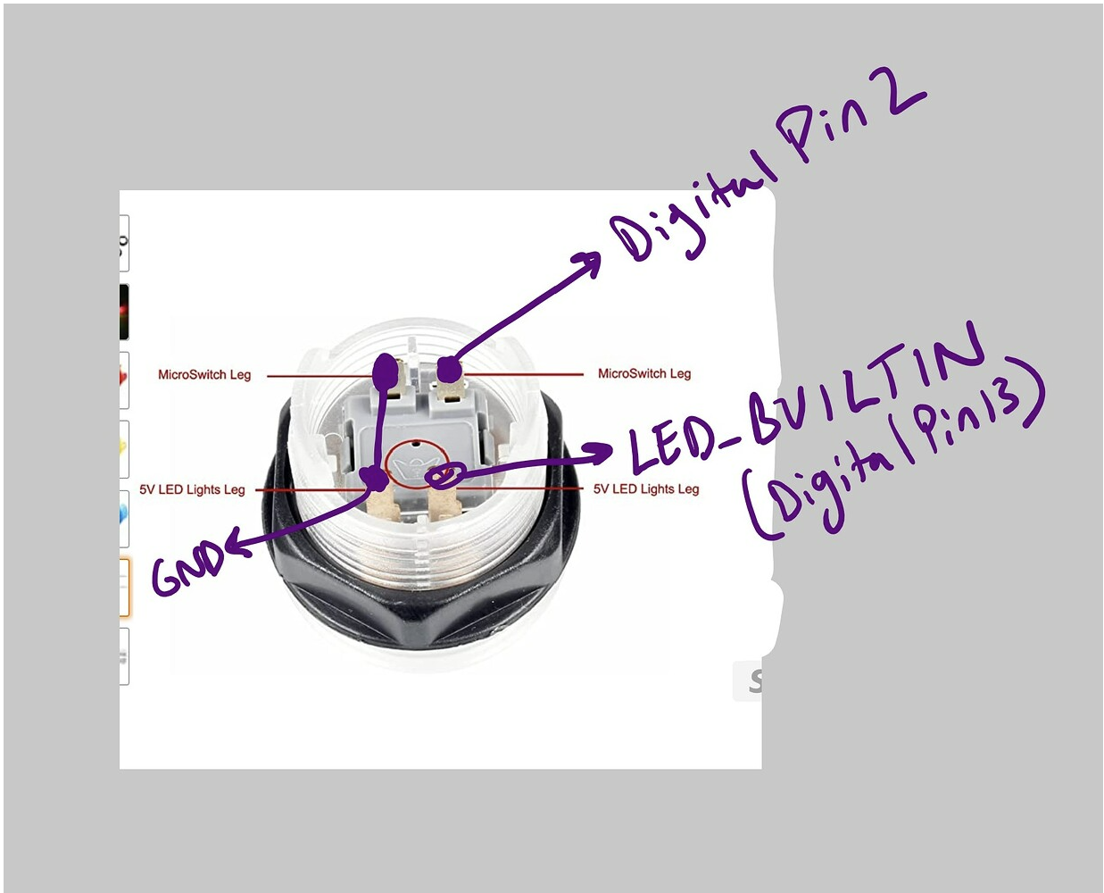
One crucial challenge in creating the “music box,” was that we wanted to use Arcade LED Button but we did not have access to the manual. Alisa tried researching online, and thought it seemed like the LED button needed connections to one positive (+) and GND (-) for the LED, as well as one positive (+) and GND (-) for the button itself. She tried this based on the colours of the cable (2 red and 2 black) she found soldered already. However, upon further research, Alisa found out that these cable colours are misleading…
Alisa inspected the component and found ‘BAOLIAN’ on the component as possibly the brand name. She did further research online and found two useful sources:
- ezbutton library resource- https://arduinogetstarted.com/tutorials/arduino-button-library
- https://forum.arduino.cc/t/using-arcade-buttons-solved/677694
One of these sources includes a diagram explaining connections as shown below. Notice the crown – this was also on the component. Given that it was circled, it must be important that the crown was facing upwards. I connected it in this way, edited the code from the forum, and the LED button lights up when I press it!
I used the gyroscope of the MPU-6050 for my last project, but MPU-6050 contains both a gyroscope and acceleromter. While the gyroscope is smooth (since it uses integration), it has the problem of accumulating errors over time. On the other hand, the accelerometer readings fluctuate very much, but are very accurate. Therefore, to balance accuracy and smoothness, I needed to combine gyroscope readings with accelerometer readings through a Kalman filter. I used this playlist to help me: the accelerometer calibration must be done manually as in video 14, and video 15 shows how gyroscope and accelerometer readings can be combined.
To have music box play different notes depending on orientation, the code needed to integrate if conditions checking whether the filtered roll angle and filtered yaw angle read from the readings combining gyroscope and accelerometer are within certain ranges.
In making the FSR keyboard some of the challenges we encountered included faulty resistors that detected readings even when not pressed and for this we had to try out each one of the resistors separately and this was very resourceful.
Another challenge was that the buzzer only played one frequency and also because tone() is a non-blocking function at a time and therefore playing a chord as was the original plan became a challenge. We therefore settled to using only notes unless we had a buzzer for each fsr.
3. Video
4. Reflection and ideas for future work or improvements
One key limitation we faced was the Arduino UNO’s constraint of only six usable analog input pins for AnalogRead(), which restricted us to mapping just six musical notes for the FSR keyboard. Ideally, we would have included a seventh note to complete a full octave. In future iterations, we could consider using a mega arduino with more analog input options.
Additionally, a valuable improvement for the music box would be providing real-time feedback to the user indicating which note is currently being played. This could be achieved by incorporating an OLED display, an array of LEDs corresponding to each note, or even serial monitor outputs during development. These enhancements would improve usability and allow for a more intuitive and engaging musical experience.