
For this week’s assignment, we were tasked with building a project that controls at least one LED using a digital sensor and another using an analog sensor. Inspired by the iconic flashing lights of police sirens, I created a setup where two LEDs alternate in a flashing pattern, mimicking the red and blue lights with a twist, you can control the flashing speed in real-time.
Video link :
https://drive.google.com/drive/folders/162WwnI-EoY3XR8ZpefkEw1aVkdSKWeLl?usp=drive_link
Components used :
– Arduino Uno
– Push Button (Digital Sensor)
– Potentiometer (Analog Sensor)
– Red LED
– Blue LED
– 2 330Ω Resistors
– Breadboard & Jumper Wires

How it Works:
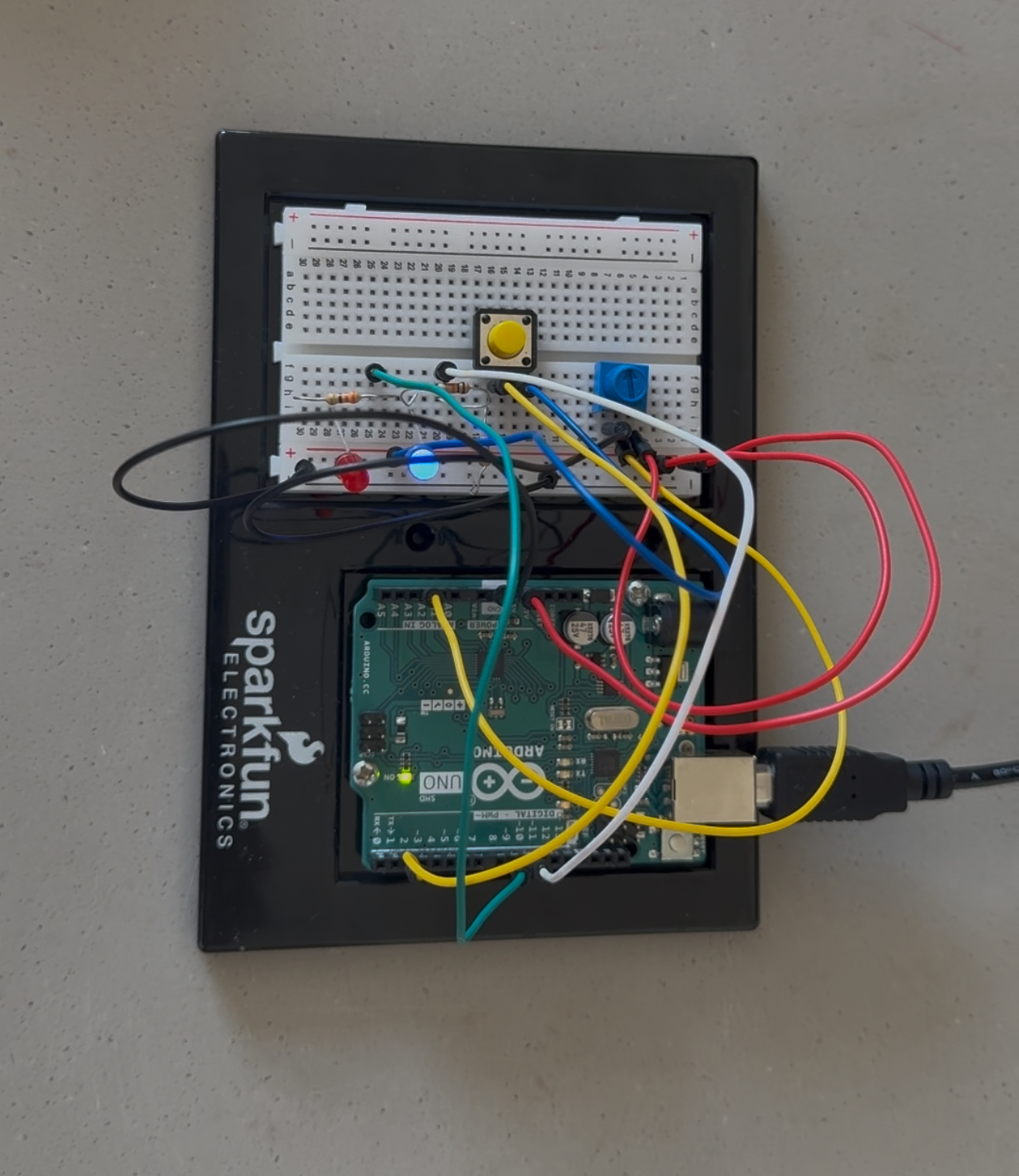
The system is activated with a push button, which acts as the digital trigger. Once pressed, the LEDs begin their alternating flashing sequence, simulating the back-and-forth of police siren lights.
The potentiometer controls the speed of the siren lights. Its analog value is read and mapped using the map() function to determine the timing of the red LED’s fade cycle. The red LED smoothly fades in and out using analogWrite(), and the duration of this full cycle is used to time the LED transitions.
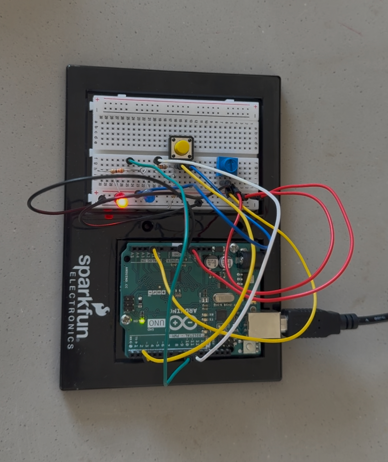
When the red LED finishes fading out, the blue LED turns on and remains lit for the same duration that the red LED is off. As soon as the red LED begins its next fade-in cycle, the blue LED turns off. This creates a continuous alternating pattern between red and blue LEDs, closely resembling the flashing of police lights.
One of the main challenges I faced was ensuring that the blue LED only turns on when the red LED is completely off. Initially, the timings between the LEDs were slightly off, which caused both LEDs to overlap or leave gaps between transitions.
Perfecting the fade timing and ensuring the blue LED’s on-time was synced precisely with the red LED’s off-time took some fine-tuning. I had to carefully balance the delays and the mapped potentiometer values to make the flashing appear smooth and consistent, without any flicker or overlap.
// Pin definitions
const int POT_PIN = A2;      // Potentiometer connected to A2
const int BUTTON_PIN = 2;    // Push button connected to D2
const int RED_LED_PIN = 9;   // Red LED connected to D9
const int BLUE_LED_PIN = 10; // Blue LED connected to D10

// Variables
int potValue = 0;
bool buttonState = false;
bool lastButtonState = false;
bool systemActive = false;

// Red LED fading variables
unsigned long fadeStartTime = 0;
int fadeDuration = 2000;     // Default fade duration (in ms)
int currentBrightness = 0;   // Current red LED brightness
enum FadeState { FADE_IN, FADE_OUT, GAP, IDLE };
FadeState fadeState = IDLE;

void setup() {
  // Initialize pins
  pinMode(BUTTON_PIN, INPUT_PULLUP);
  pinMode(RED_LED_PIN, OUTPUT);
  pinMode(BLUE_LED_PIN, OUTPUT);

  // Start with all LEDs off
  digitalWrite(BLUE_LED_PIN, LOW);
  analogWrite(RED_LED_PIN, 0);
}

void loop() {
  // Read potentiometer and map to fade duration (100ms to 5000ms)
  potValue = analogRead(POT_PIN);
  fadeDuration = map(potValue, 0, 1023, 100, 5000);

  buttonState = digitalRead(BUTTON_PIN);

  if (buttonState == LOW && lastButtonState == HIGH) {
    // Toggle system on/off
    systemActive = !systemActive;

    if (systemActive) {
      // Start the cycle
      fadeState = FADE_IN;
      fadeStartTime = millis();
    } else {
      // Turn everything off
      fadeState = IDLE;
      digitalWrite(BLUE_LED_PIN, LOW);
      analogWrite(RED_LED_PIN, 0);
    }
    delay(50); // Debounce delay
  }
  lastButtonState = buttonState;

  // Only process fading if system is active
  if (systemActive) {
    unsigned long currentTime = millis();
    unsigned long elapsedTime = currentTime - fadeStartTime;

    switch (fadeState) {
      case FADE_IN:
        currentBrightness = map(elapsedTime, 0, fadeDuration, 0, 255);
        digitalWrite(BLUE_LED_PIN, LOW); // Blue off during fade

        if (elapsedTime >= fadeDuration) {
          fadeState = FADE_OUT;
          fadeStartTime = currentTime;
        }
        break;

      case FADE_OUT:
        currentBrightness = map(elapsedTime, 0, fadeDuration, 255, 0);
        digitalWrite(BLUE_LED_PIN, LOW); // Blue off during fade

        if (elapsedTime >= fadeDuration) {
          fadeState = GAP;
          fadeStartTime = currentTime;
          digitalWrite(BLUE_LED_PIN, HIGH); // Blue on during gap
        }
        break;

      case GAP:
        currentBrightness = 0;

        if (elapsedTime >= fadeDuration) {
          fadeState = FADE_IN;
          fadeStartTime = currentTime;
          digitalWrite(BLUE_LED_PIN, LOW); // Blue off when fade starts
        }
        break;

      case IDLE:
        // Do nothing
        break;
    }

    // Update red LED brightness
    analogWrite(RED_LED_PIN, currentBrightness);
  }

  delay(10);
}
In the end, it all helped me better understand PWM control, timing logic, and how to coordinate multiple components using both analog and digital inputs on the Arduino.