
Schematics
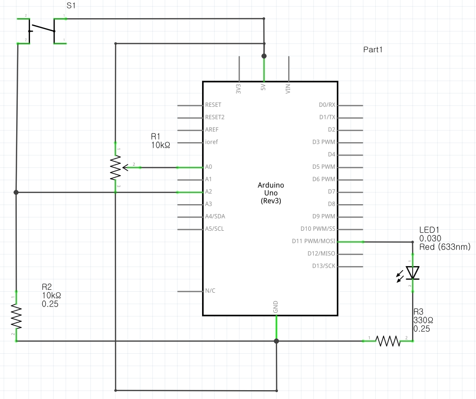
The schematic is made to be compatible throughout the assignment.
This schematic is used for Exercise 2.
Exercise 1:
-
-
make something that uses only one sensor on arduino and makes the ellipse in p5 move on the horizontal axis, in the middle of the screen, and nothing on arduino is controlled by p5
-
Arduino Code (Credit: Hessa):
void setup() {
  Serial.begin(9600); // initialize serial communications
}

void loop() {
  // read the input pin:
  int potentiometer = analogRead(A0);
  // remap the pot value to fit in 1 byte:
  int mappedPot = map(potentiometer, 0, 1023, 0, 255);
  // print it out the serial port:
  Serial.write(mappedPot);
  //Serial.println(mappedPot);
  // slight delay to stabilize the ADC:
  delay(1);
}
Exercise 2:
-
-
make something that controls the LED brightness from p5
-
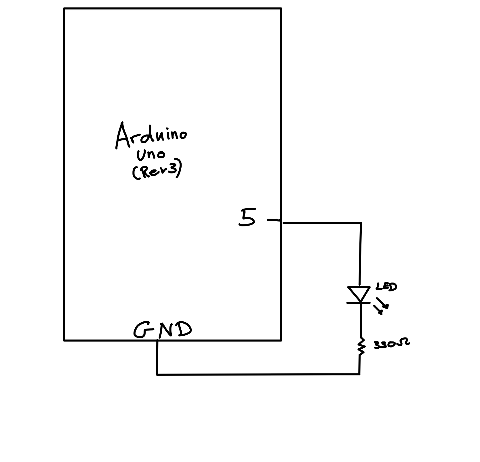
Arduino Code (Credit: Aisha):
int LED = 5;

void setup() {
  Serial.begin(9600);
  pinMode(LED, OUTPUT);
  // start the handshake
  while (Serial.available() <= 0) {
    Serial.println("Wait");  // send a starting message
    delay(300);               // wait 1/3 second
  }
}

void loop() {
  // wait for data from p5 before doing something
  while (Serial.available()) {
    int brightness = Serial.parseInt();
    if (Serial.read() == '\n') {
      analogWrite(LED, brightness); // turn on LED and adjusts brightness
      Serial.println("LIT");
    }
  }
}
Exercise 3:
-
-
take the gravity wind example (https://editor.p5js.org/aaronsherwood/sketches/I7iQrNCul) and make it so every time the ball bounces one led lights up and then turns off, and you can control the wind from one analog sensor
-
Code is included in the above sketch.