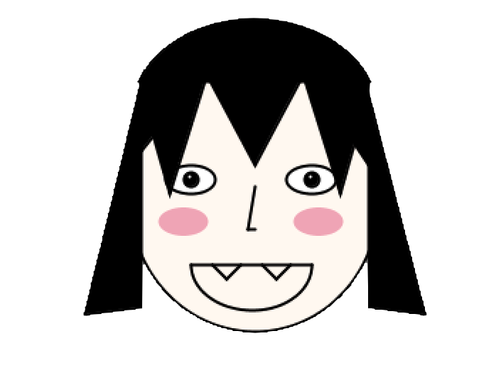
My idea for my final project was to create the game “WHAC-A-MOLE” using Arduino as a controlling system for the game. But because I wanted my game to be unique I thought I’d change the theme and change the game to “WHAC-A-VAMP” so whacking vampires instead (which if you ask me is way cooler). I chose a vampire because (not sure if I mentioned it in my first assignment or not, but I made a “vampire themed self-portrait??”)
Yes, she’s supposed to be a vampire. What do you mean she doesn’t look like one?
Anyways, so users whack my vampire self-portrait. Now that I think about it my idea is kind of problematic-
IDEA (but seriously):
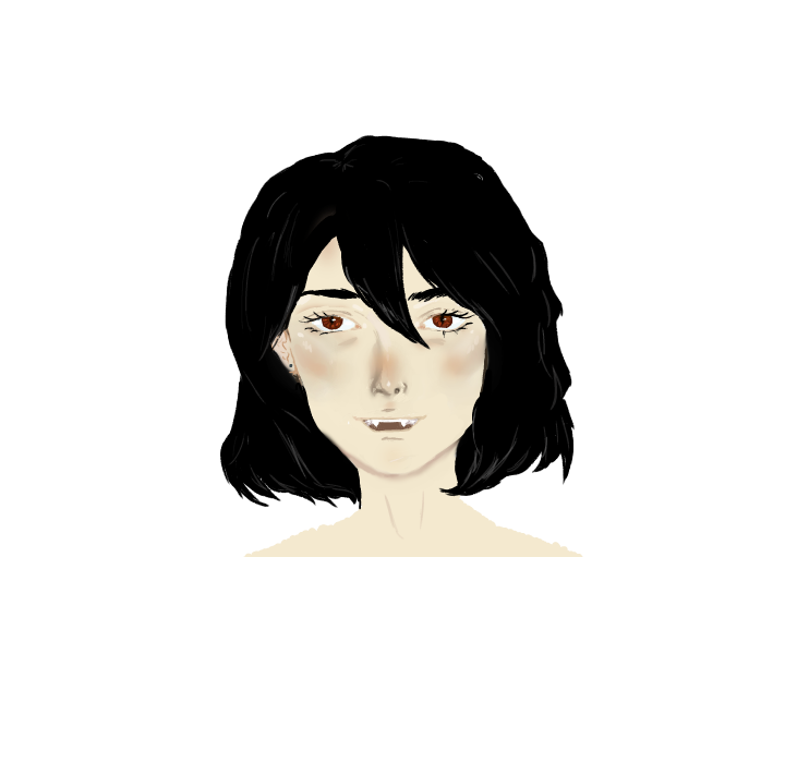
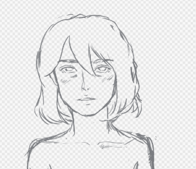
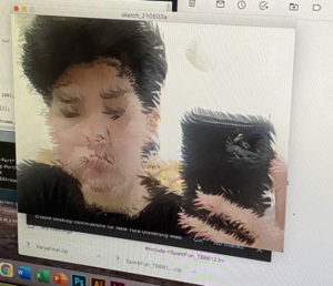
For the game itself, I re-drew my self-portrait:
I was hoping I’d finish it completely to put the finished piece in the main menu but my program quit and only the sketch was saved. Basically, all my painting efforts have gone to waste and thankfully I screenshotted the face at least to include it in my game. This is what’s been saved ;-;
I use the same code for the stars in my dancing planets project in the background because I really liked it and I did not want a boring plain background.
APPLICATION AND CHALLENGES:
My game took much more time than anticipated. Whenever I tried to solve a problem a new problem arises. My highest streak of coding for this assignment was 10 hours straight! (not my highest streak for coding btw) But, it was definitely very exhausting. My main problems were the following:
Wiring problems (honestly I’m embarrassed that I faced them)
I did not know that I was not inserting my buttons correctly on the breadboard! The buttons were always loose, but I just thought it was how they were designed. So, when I run my program, I would think I pressed the button but it is just loose, thus I’d think it is a logical problem. I only fixed this problem after the professor pointed it out lol.
Logical problems
I faced problems because there would be loophole in my code that I could not see. For that, I needed a fresh pair of eyes to have a look at it and point out how to fix them.
My first problem was that when I would click to begin the game, the screen would go back and forth from menuScreen to gameScreen. I solved that by using boolean variables instead of using integer variables.
final int MENUSCREEN = 0;
final int GAMESCREEN = 1;
final int AGAINSCREEN = 2;
int screenState;
those were the previous variables and switching to boolean fixed it
Problems regarding functions I’m not familiar with
This problem occurred with the serialEvent function. Because I was not aware of how to use it properly, I used it like it is a normal function. And so, I would call it whenever I would call the drawGame function and that interrupted the button values from Arduino. The fix was to not call it, it would read the Arduino information whenever it receives it.
In summary, my final project was a series of failed experiments.
My original goal was to use the p5.speech library to create something for Zoom classes. The user would be alerted every few minutes if they ended up falling asleep on their pillow using a capacitative touch sensor. I also hoped to record the transcript of the meeting/class in session and play some sort of alarm if the user’s name was said, urging them to get up.
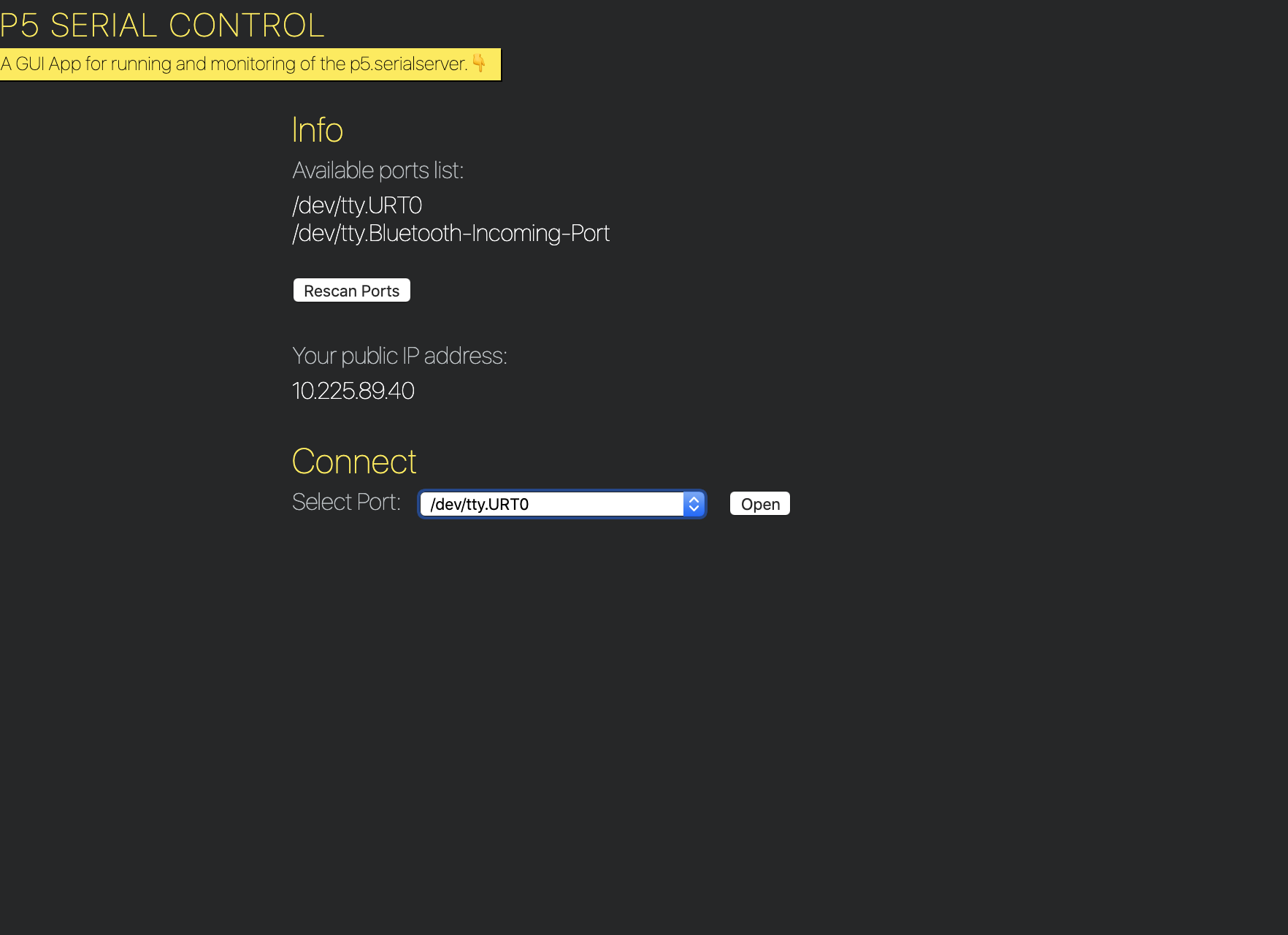
I ended up playing around with this idea, using the p5.serialcontrol program to communicate between p5.js and Arduino. While it is cool that this exists, it was a bit clunky in terms of workflow in terms of connecting ports, etc. Additionally, I wasn’t fully comfortable using the p5.speech library to record transcripts. Other than the technical problem of pipes breaking, I didn’t think it was okay to record the transcripts due to user privacy. Additionally, the speech recognition was a bit better than expected but probably still only a 65% recognition of the names of friends I tried, so I thought it would still make microaggressions in its failure to understand certain friends’ names, etc.
Screenshot of p5.serialcontrol app
Thus, I needed to repivot my idea. I really wanted to keep the capacitative touch element of the project because this was something I had never been exposed to. I decided to maintain the original spirit of the project as well…something that could help me personally. I have lots of low energy periods due to insomnia and perpetual migraines, but I still have to do my best to complete my work. However, amidst the low energy, I need to make sure I don’t completely fall asleep. It’s not very predictable so setting an alarm ahead of time is not something I would know to do. Thus, I thought the capacitative touch sensor could be useful to see if I do end up falling asleep–having a sensor in my pillow could detect this and set into motion a way to wake me up.
From there I imagined having a combination of vibrations and sound to wake me up. I originally considered using an LED to show whether the sensor was working, but thought bright lights and migraines aren’t the greatest of combinations. In our class check-in, Aaron suggested using motors to create the vibrations.
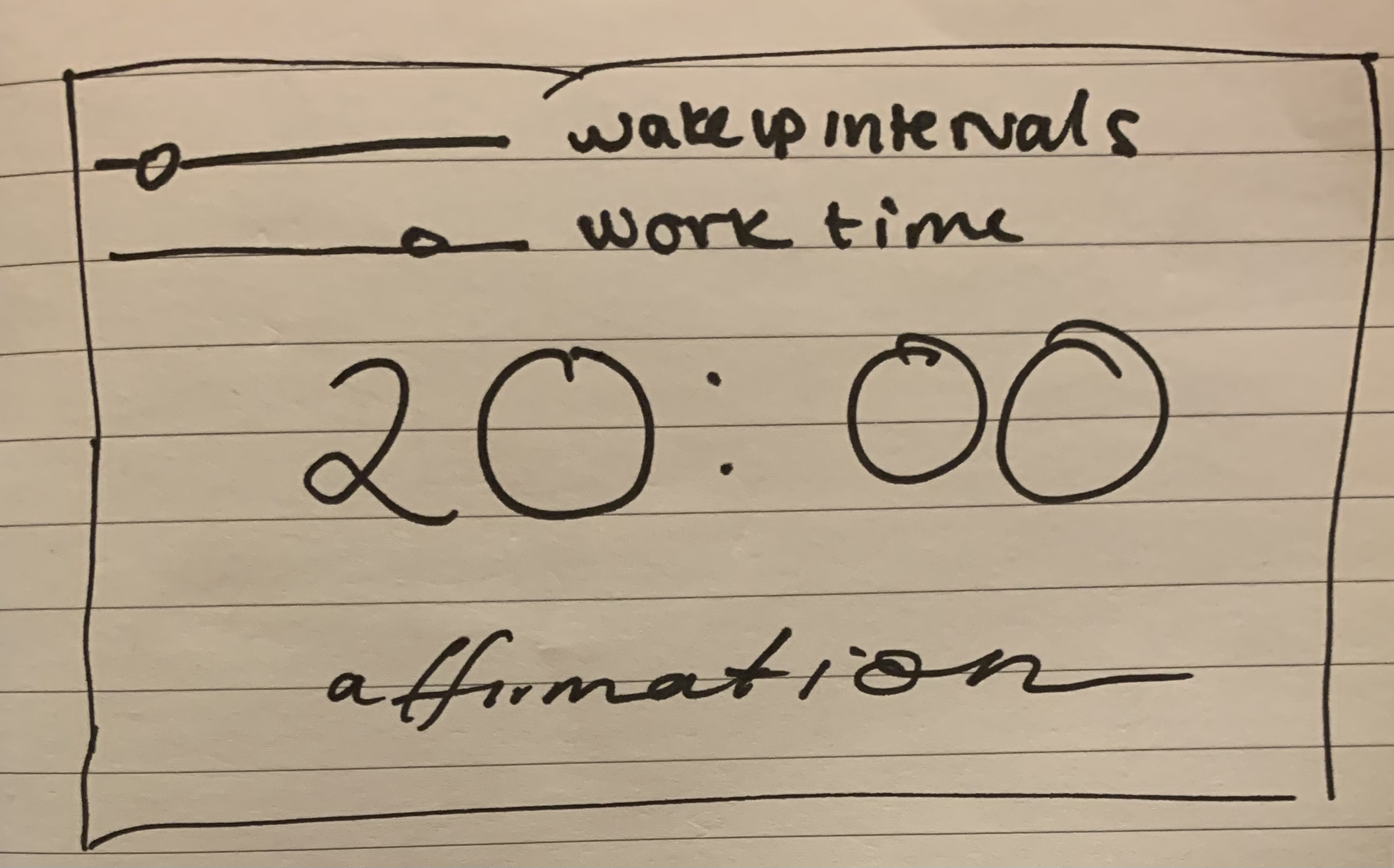
Sketch of Program
I was also trying to brainstorm what the Processing program could look like. Having structured work time and making sure I take breaks is important to make sure I don’t get too fatigued. Thus, I thought it could be interesting to make my own version of the Pomodoro method. Additionally, doing work tends to bring out a lot of negative thought patterns, so I wanted to integrate some positive energy into the program. I found this affirmation API that I could pull a random message from.
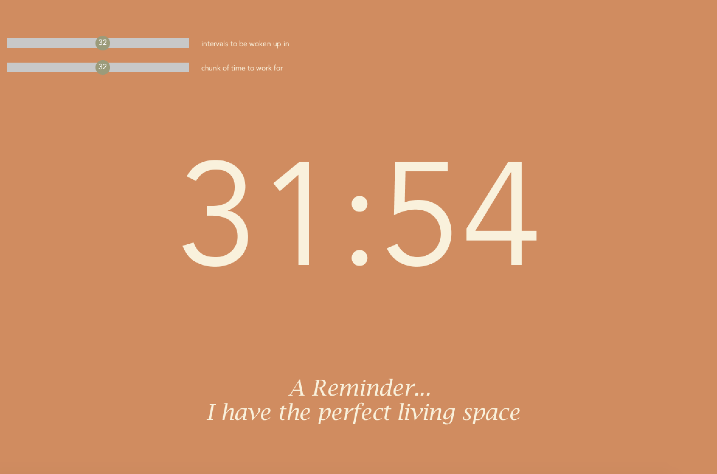
Creating the scrollbars was a bit manual, but I had help from the Scrollbar Processing documentation example. I modified it to make more simple and more to the aesthetic of the program and used a map function instead of calculating the ratio of the slider’s position to the slider’s width. I also added text to know what the current value of the slider is.
I designed a color palette using Coolors and tested it for accessibility for various visual abilities using their tool.
Creating the stopwatch display was a bit tricky because I wanted the new time to appear any time the scrollbar was moved. I ended up creating a helper function to calculate the new timer value. This would be used in the calculateTime function. Another issue I had was displaying the time in a way easy for the reader to understand. For instance, simply using the numerical value of minutes and seconds wouldn’t work for the 60 second mark (the user would expect to see 00 instead of 60) and for the second ticks less than 10 (the user would expect to see :01 instead of :1). I ended up just using an if statement to check for these edge cases, but I’m sure there is a smarter way to do this.
The final aspect of the front page of the program was the affirmations. Using the http.requests library was pretty straightforward, but the response was not in a form conducive for using JSON. I ended up just creating a substring of what was returned to include only the actual message part.
I kind of don’t vibe with some of the affirmations in the API but here’s a home screen of the program
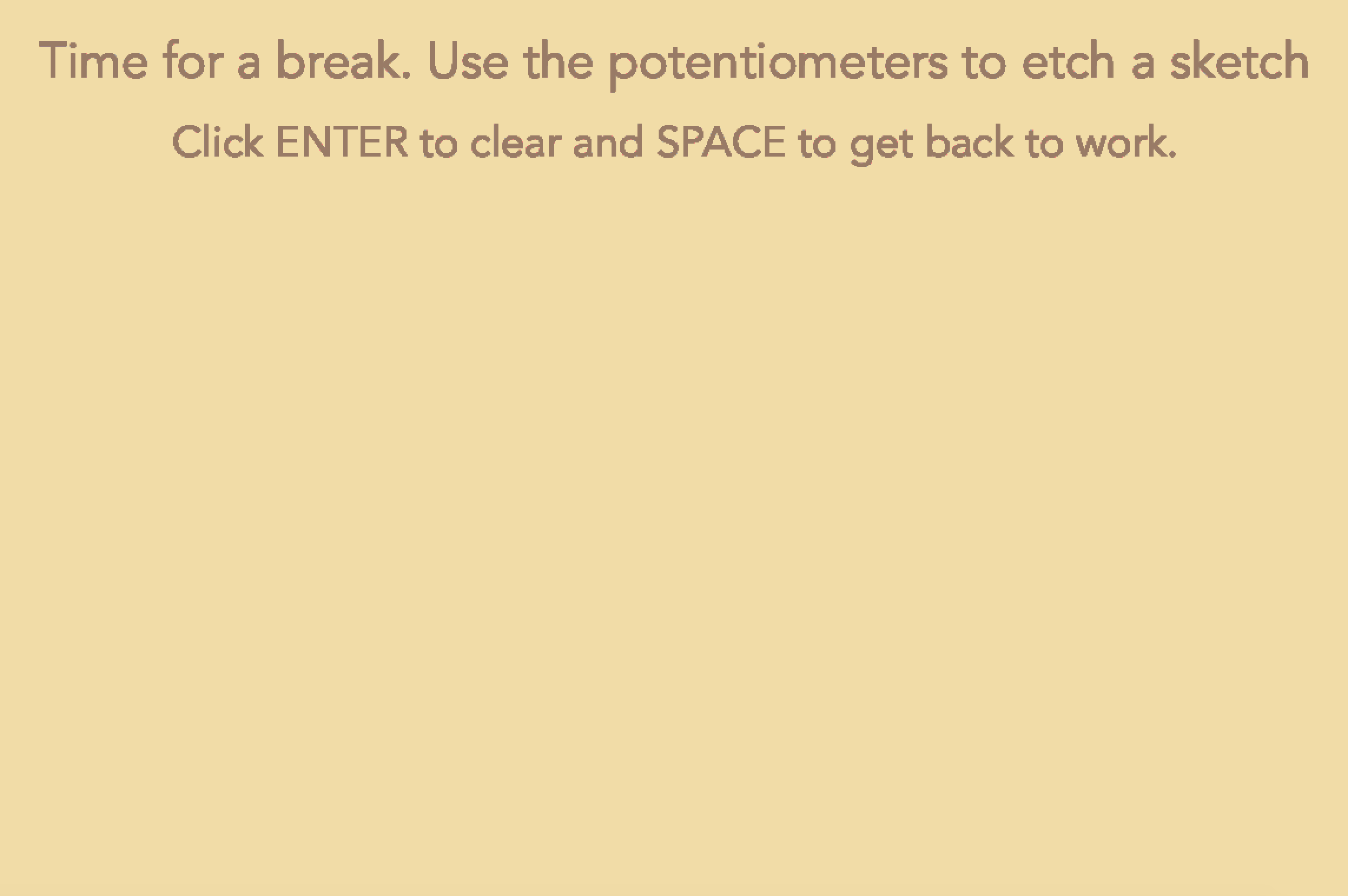
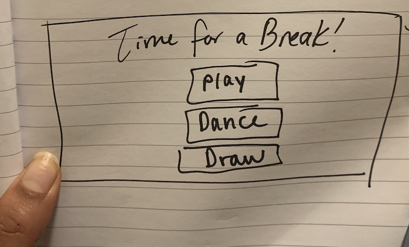
I also wanted to include another element of interaction with the Arduino. Thus, I thought I could create something for the break period of the program that involved using a hardware component. I considered doing a dance break–playing music with dancing LEDs, but had done something similar for one of the weekly projects and wanted to learn something new. I also thought it could be interesting to do a small mini game using the buttons on Arduino as controls, but I’m a bit tired of making games in all honesty. Thus, I decided to do something involving drawing. From the moment we starting working with potentiometers, they reminded me of the little knobs on those toys Etch-a-Sketch–I decided to build a mini Etch-a-sketch for the break part of the program!
Screen to etch a sketch for break part of program
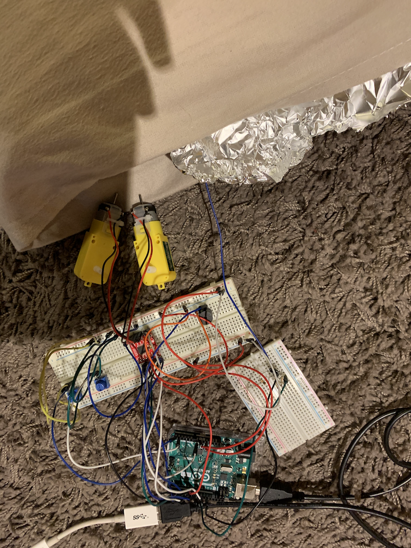
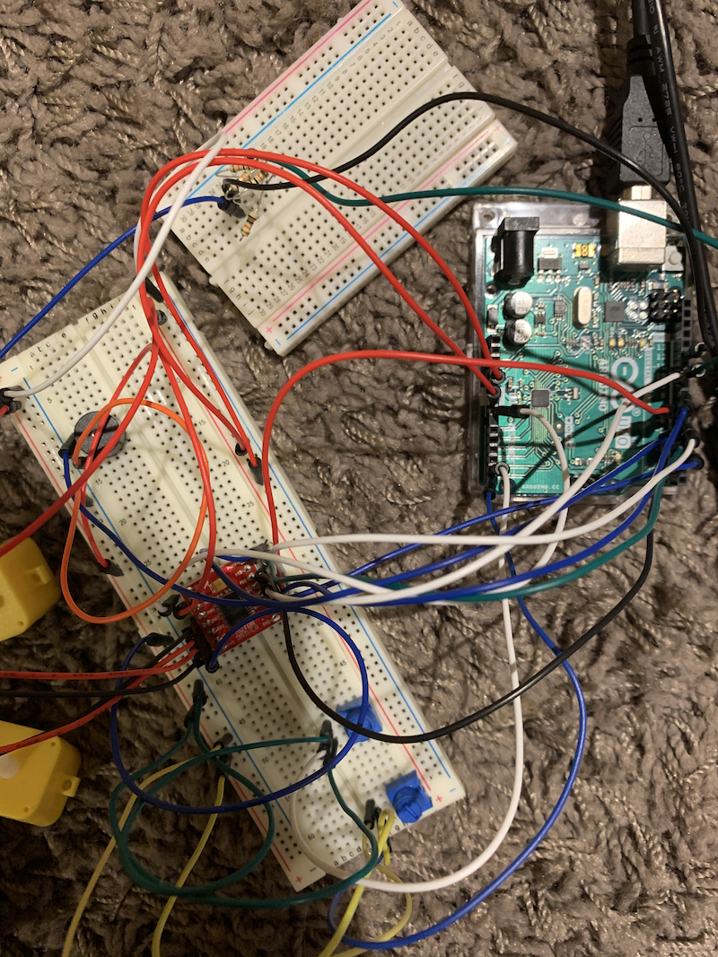
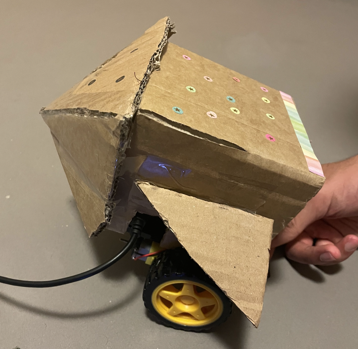
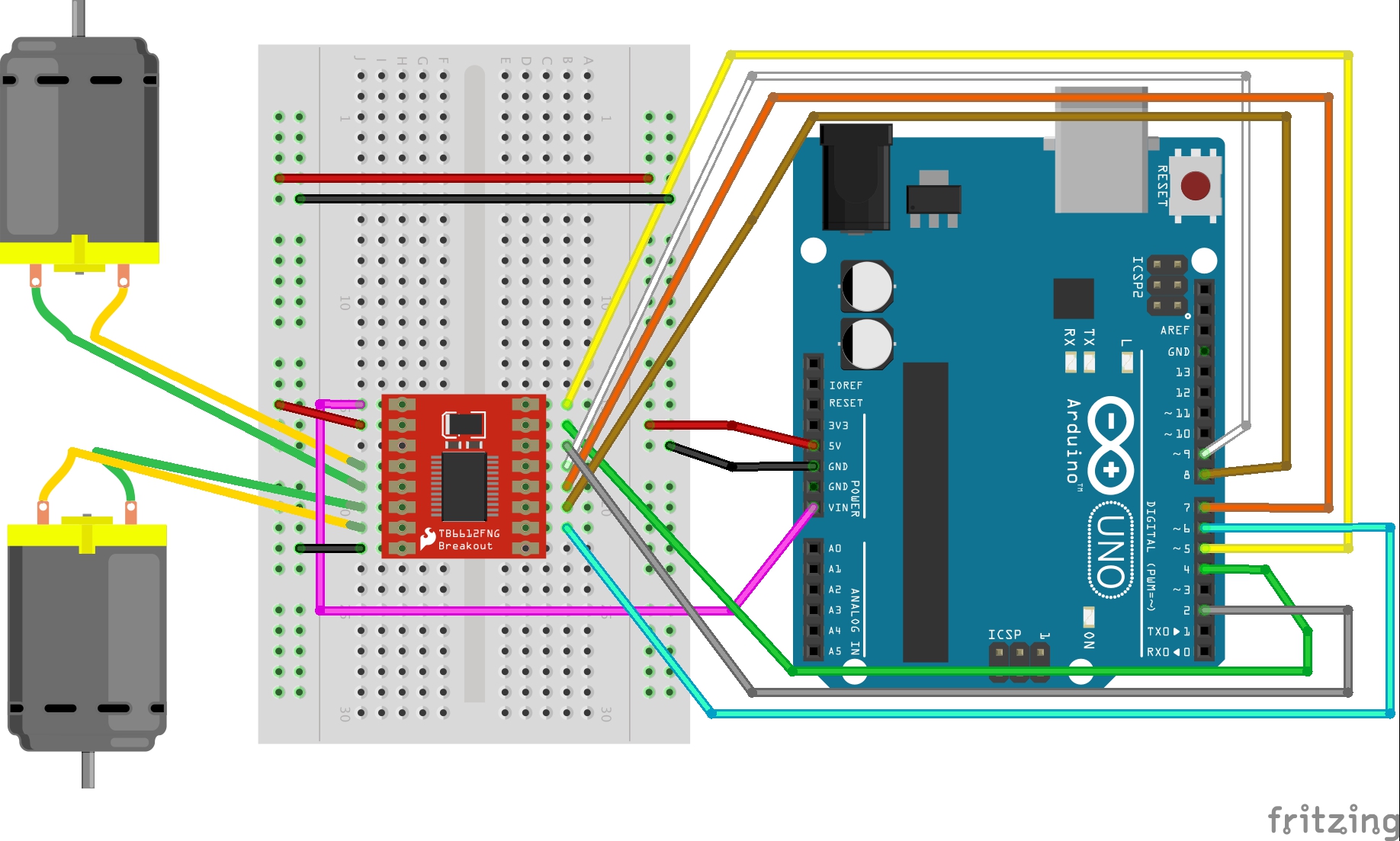
In terms of my hardware, I used the capacitative touch sensor. I was inspired by the Love You Pillow project on the Arduino Hub to use foil for the sensor. I had to experiment a bit with finding the right threshold, but overall, it worked pretty smoothly and consistently. I used the motor shield to connect two motors to create the vibrations…the code and wiring was heavily remixed from the class we spent on motors. I also used a piezo buzzer and two potentiometers.
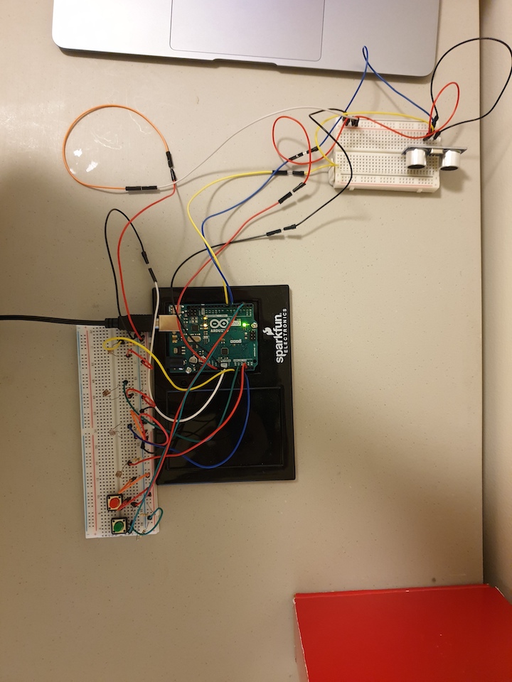
Overview of Component SetupCloseup of Wiring
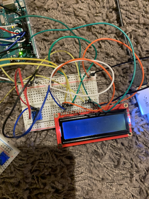
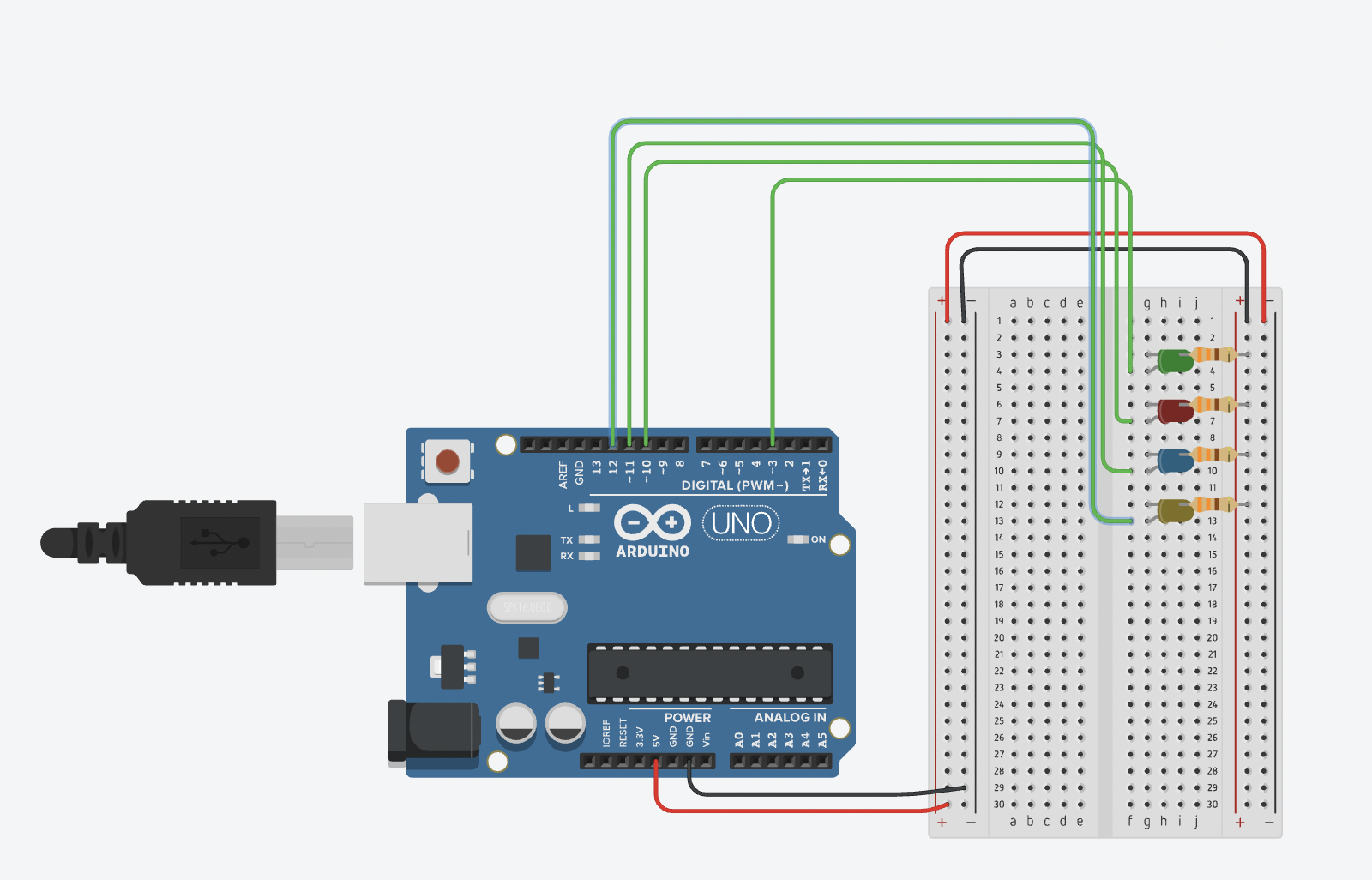
I also experimented a bit with the LED display–I was thinking of randomly sending messages like “Hydrate” and “Stretch,” but I ran out of pins to include it in the final setup, already using some of the analog pins as digital pins.
LCD Display Setup
Overall, I’m not very content with the project. I know I’m capable of better work, but for where I’m at in terms of energy, I think I did my best. There’s definitely a lot of room for improvement. It could be cool to include the LCD Display with user choice of messages on the Processing screen (hydrate, eye break, stretch, breathe deeply). It could be cool to have more options for what to do on the break. I realize I don’t really like drawing with the etch a sketch, so it could be more useful to explore other potential activities like making a mini piano or game, etc. I think the user interface of the etch a sketch could be made more interesting by having more user input in choosing a color etc.
sketch of potential choice of break
Here’s a walkthrough of my project:
CODE:
Arduino:
#include <CapacitiveSensor.h>
#include <SparkFun_TB6612.h>
//#include <LiquidCrystal.h>

#define AIN1 2
#define BIN1 7
#define AIN2 4
#define BIN2 8
#define PWMA 5
#define PWMB 6
#define STBY 9


//LiquidCrystal lcd(19, 18, 17, 16,11, 3);
// these constants are used to allow you to make your motor configuration
// line up with function names like forward.  Value can be 1 or -1
//from motor library example code
const int offsetA = 1;
const int offsetB = 1;
int duration = 2000;
Motor motor1 = Motor(AIN1, AIN2, PWMA, offsetA, STBY);
Motor motor2 = Motor(BIN1, BIN2, PWMB, offsetB, STBY);
//pressed boolean indicates whether the pillow sensor senses touch
int pressed = 0;
long timer;
//threshold for pillow sensor; if greater than threshold, there is touch
int threshold = 30;
//timeLength variable from first scrollbar in Processing program
int timeLength;

CapacitiveSensor   cs_4_2 = CapacitiveSensor(10,12);        //12 is sensor pin
//count indicates what level of intensity to be woken up
int count = 0;
int piezoPin = 3;

int pot1 = A4;
int pot2 = A5;

void setup()
{
   cs_4_2.set_CS_AutocaL_Millis(0xFFFFFFFF);     //from capacitive sensor library
   Serial.begin(9600);
   Serial.println(0,0);

//   lcd.begin(16, 2);                 //tell the lcd library that we are using a display that is 16 characters wide and 2 characters high
//  lcd.clear();                      //clear the display
}

void loop()  {
 while (Serial.available()) {
  //read from Processing
  timeLength = Serial.parseInt();
  //turns into minutes, change this value if you want the interval in seconds
  timeLength *= 60000;

   if (Serial.read() == '\n') {
    //sends potentiometer values to processing
  int val1 = analogRead(pot1);
  Serial.print(val1);
  Serial.print(",");
  int val2 = analogRead(pot2);

  Serial.println(val2);
   }
  }

//   lcd.setCursor(0, 1);
//  lcd.print(timeLength);
//
    long start = millis();
    long cap =  cs_4_2.capacitiveSensor(30);
    //if the sensor value is greater than the threshold and has not yet been activated
    //starts sensor and level count
    if (cap > threshold && pressed != 1){
      pressed = 1;
      timer = millis();
      count = 0;

    } else if (cap > threshold && pressed == 1) {
      pressed = 1;
      //if sensor value is less than threshold, turn pressed off
    } else if (cap < threshold && pressed == 1) {
      pressed = 0;
    }
  if (pressed == 1) {
//   lcd.setCursor(0, 0);
//  lcd.print("sensor on");
//  lcd.setCursor(0, 1);
//  lcd.print(timeLength);

//after every X minutes
  if (millis() - timer >= timeLength) {
    timer = millis();
   level(count);
   count += 1;
  }
  }
}
//function creates intensity of response to wake up depending on level
void level(int count) {
  switch(count){
  case 0:
    vibrate(0);
    break;
  case 1:
    vibrate(1);
    break;
  case 2:
    vibrate(2);
    break;
  case 3:
    vibrate(2);
    tone(piezoPin, 200, duration);
    break;
  default:
    vibrate(3);
    tone(piezoPin, 500, duration);
    break;
  }
}
//vibrate function to determine speed based on level
void vibrate(int level) {
  int sp = 0;
  if (level == 0) {
    sp = 75;
  } else if (level == 1) {
    sp = 120;
  } else if (level == 2) {
    sp = 180;
  } else {

    sp = 255;
  }
  //moves the motors
  motor1.drive(sp,duration);
  motor2.drive(sp,duration);
  //stops motors
  motor1.brake();
  motor2.brake();
}
Processing:
import http.requests.*;
import processing.serial.*;

Serial myPort;

Scrollbar bar1;
Scrollbar bar2;

int first = 0;
int second = 0;
float lastX = 0;
float lastY = 0;
//Button play;
//Button dance;
//Button draw;

int seconds;
int minutes;

int timer;
int startTime;

PFont lucida;
PFont avenir;
int state = 0;
String response;
void setup() {
    size(1200, 800);
    lucida = createFont("Lucida Bright Italic", 36);
    avenir = createFont("Avenir", 12);
    textAlign(CENTER);
    background(#D08C60);
    //requests affirmation from api
    GetRequest affirm = new GetRequest("https://dulce-affirmations-api.herokuapp.com/affirmation");
    affirm.send();
    response = affirm.getContent();
    //finds string of affirmation
    response = response.substring(12, response.length() - 3);

    //Scrollbar(x, y, width, height, min val, max val)
    bar1 = new Scrollbar(20, height/10, 300, 16, 1, 60);
    bar2 = new Scrollbar(20, height/10 + 40, 300, 16, 1, 60);
    //finds initial time of scrollbars
    adjustTime();

     //play = new Button("PLAY", width/2 - 150, height/3, 300, 80, 2);
     //dance = new Button("DANCE", width/2 - 150, height/3 + 120, 300, 80, 3);
     //draw = new Button("DRAW", width/2 - 150, height/3 + 240, 300, 80, 4);

     //sets up serial communication
     String portname=Serial.list()[2];
      myPort = new Serial(this,portname,9600);
      myPort.clear();
      myPort.bufferUntil('\n');
      delay(1000);

}

void draw(){
//if home screen
  if (state == 0) {
    background(#D08C60);
    //scrollbars - draw and update if user input
    bar1.update();
    bar2.update();
    bar1.display();
    bar2.display();
    fill(#F9F1DC);
    //displays affirmation
    textFont(lucida);
      text("A Reminder...", width/2, height - 140);
      text(response, width/2, height - 100);
    textAlign(LEFT);
    textFont(avenir);
    text("intervals to be woken up in", 340, height/10 + 5);
    text("chunk of time to work for", 340, height/10 + 45);
    //calculates and displays time
    calculateTime();
  //} else if (state == 1) {
  //    background(#F1DCA7);
  //    textFont(avenir);
  //    textSize(72);
  //    fill(#997B66);
  //    text("Time for a break!", width/2, height/8);
  //    play.display();
  //    dance.display();
  //    draw.display();
  //    play.update();
  //    dance.update();
  //    draw.update();
  } else if (state == 2) {
    //drawing screen game
      textFont(avenir);
      textSize(42);
      fill(#997B66);
      text("Time for a break. Use the potentiometers to etch a sketch", width/2, height/8);
      textSize(36);
      text("Click ENTER to clear and SPACE to get back to work.", width/2, height/8 + 65);
      //maps potentiometer value to some coordinate on the screen
      float x = map(first, 0, 1023, 0, width);
      float y = map(second, 0, 1023, height/4, height);
      //finds random color for the line
      stroke(random(0,255), random(0,255), random(0,255));
      //idea for saving last coordinate from this project: http://graysonearle.com/edu/physcom/etch-a-sketch-arduino-processing/
      line(x, y, lastX, lastY);
      lastX = x;
      lastY = y;
  }
}
//scrollbar class for user input on first screen
class Scrollbar {
  //slider width and height
  int sw;
  int sh;
  float xpos;
  float ypos;
  //the slider position (ellipse)
  float slider_pos;
  float newpos;
  float sliderMin;
  float sliderMax;
  boolean mouseOnTop;
  boolean moved;
  boolean posChanged;
  //min and max values of slider
  int sValMin;
  int sValMax;

  Scrollbar(float x, float y, int w, int h, int minVal, int maxVal) {
    sw = w;
    sh = h;
    xpos = x;
    ypos = y - sh/2;
    slider_pos = xpos + sw/2 + sh/2;
    newpos = slider_pos;
    sliderMin = xpos;
    sliderMax = xpos + sw;
    sValMin = minVal;
    sValMax = maxVal;
    posChanged = false;
  }

  void update() {
    //if user mouseX, mouseY is on top of the scrollbar
    if (overEvent()) {
      mouseOnTop = true;
    } else {
      mouseOnTop = false;
    }
    //if mouse held and on top, then the scrollbar is being moved
    if (mousePressed && mouseOnTop) {
      moved = true;
    }

    if (!mousePressed) {
      moved = false;
    }
    //keep within the range of the slider
    //code remixed from https://processing.org/examples/scrollbar.html
    if (moved) {
      newpos = constrain(mouseX - sh/2, sliderMin, sliderMax);
    }
    //if slider value has changed
    if (abs(newpos - slider_pos) > 1) {
      slider_pos += (newpos -slider_pos);
      adjustTime();
    }
  }

  float constrain(float val, float smin, float smax) {
    return min(max(val, smin), smax);
  }
  boolean overEvent() {
    if (mouseX > xpos && mouseX < xpos + sw && mouseY > ypos && mouseY < ypos + sh) {
      return true;
    } else {
      return false;
    }
  }
  //creates the scrollbar
  void display() {
    noStroke();
    fill(200);
    rect(xpos, ypos, sw,sh);
    fill(#9B9B7A);
    //ellipse is the slider part of the bar
    ellipse(slider_pos, ypos + sh/2, 1.5 *sh, 1.5*sh);
    fill(255);
   textAlign(CENTER);
    textFont(avenir);
    //label of the actual value
    text(getVal(), slider_pos, ypos + sh/1.5);
  }

  int getVal() {
    float mapVal = map(slider_pos, xpos, xpos + sw, sValMin, sValMax);
    return int(mapVal);
  }

}
//get value from scrollbar and create a new start time
void adjustTime() {
  timer = bar2.getVal();
  startTime = millis();
}

void calculateTime() {
  seconds = 60 - ((millis() - startTime)/1000) % 60;
  minutes = timer - 1 - ((millis() - startTime) / 60000);
  //displays time in middle of screen
  textFont(avenir);
  textSize(240);
  textAlign(CENTER, BOTTOM);
  if (seconds == 60) {
    text(minutes + 1 + ":00", width/2, 2*height /3);
  } else if (seconds < 10) {
  text(minutes + ":0" + seconds, width/2, 2*height /3);
  } else {
    text(minutes + ":" + seconds, width/2, 2*height /3);
  }
  //when timer runs out, move to next screen
  if (seconds == 60 && minutes <= 0) {
    state = 2;
    background(#F1DCA7);
  }
}
//class Button {
//  String msg;
//  int xpos;
//  int ypos;
//  int w;
//  int h;
//  int cntl;

//  Button(String words, int x, int y, int w_, int h_, int st) {
//    msg = words;
//    xpos = x;
//    ypos = y;
//    w = w_;
//    h = h_;
//    cntl = st;
//  }

//  void display() {
//    noStroke();
//    if (mouseX > xpos && mouseX < xpos + w && mouseY > ypos && mouseY < ypos + h) {
//      fill(#7A6352);
//    } else {
//      fill(#997B66);
//    }
//    rect(xpos, ypos, w, h);
//    textAlign(CENTER, CENTER);
//    fill(#F1DCA7);
//    text(msg, xpos + w/2, ypos + h/3);
//  }

//  void update() {
//    //if button is clicked
//    if (mousePressed && mouseX > xpos && mouseX < xpos + w && mouseY > ypos && mouseY < ypos + h) {
//      state = cntl;
//      background(#F1DCA7);
//    }
//  }
//}

void keyPressed() {
  if (state == 2) {
    //returns to home screen if SPACE is clicked
    if (key == ' ') {
      state = 0;
    }
    //refreshes background if ENTER clicked to allow for new drawing
    else if (key == ENTER) {
    background(#F1DCA7);
    }
  }
}
void serialEvent(Serial myPort){
 String s=myPort.readStringUntil('\n');
 println(s);
  s=trim(s);
  if (s!=null){
    //gets value of potentiometer
    int values[]=int(split(s,','));
    first = values[0];
    second = values[1];
  }
  //writes to arduino the scrollbar value
  myPort.write(bar1.getVal() + "\n");
}
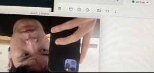
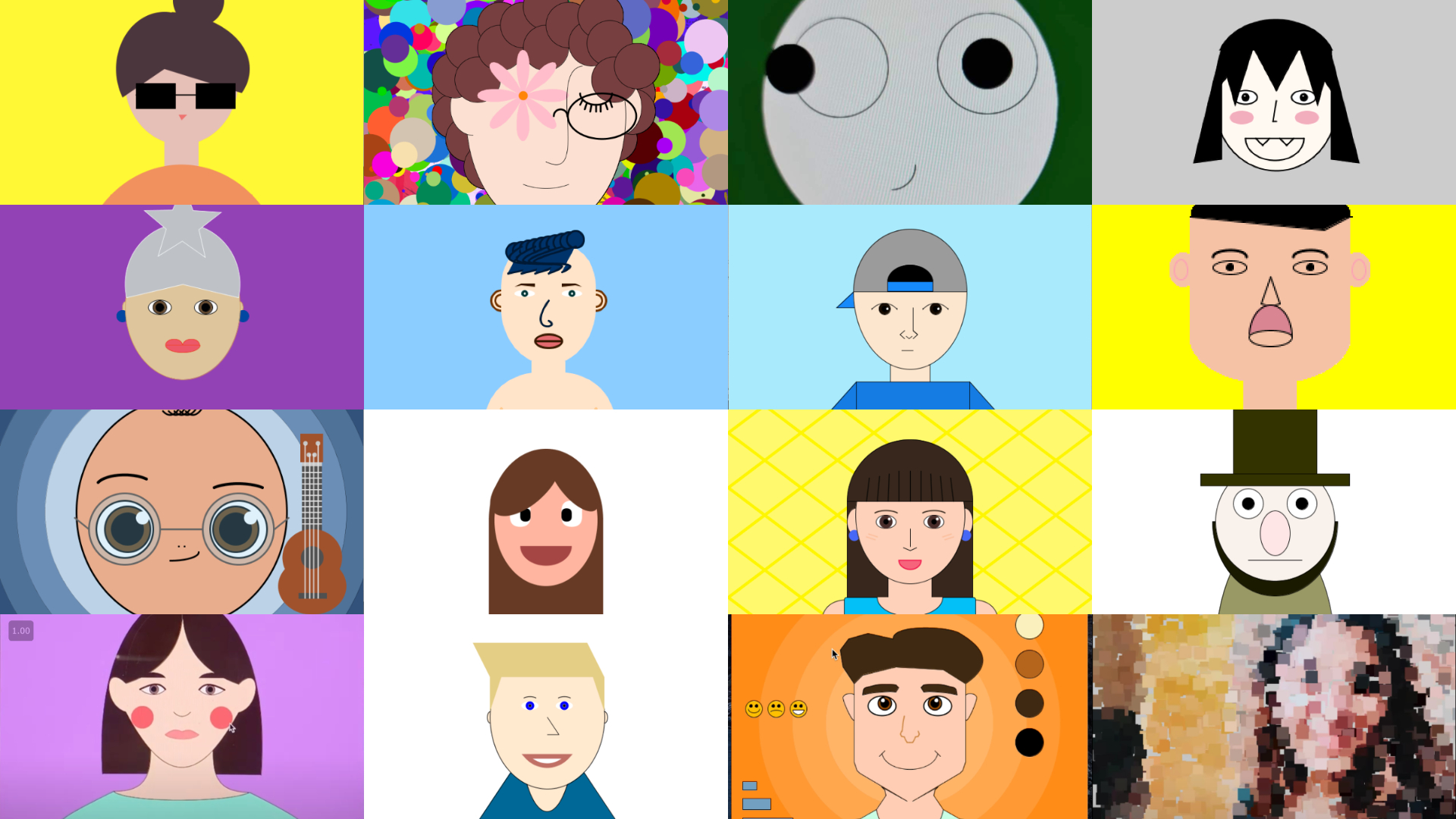
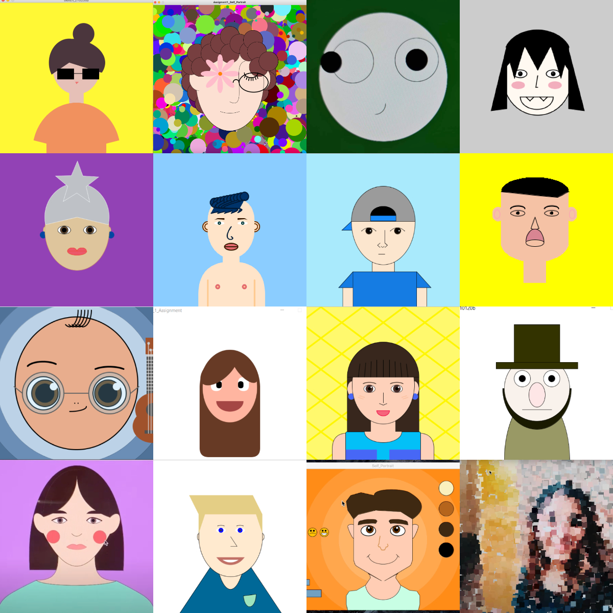
The final project turned out to be an artistic expression in its true form, developing chaotically and very unexpectedly. The essence of this project is to reflect over your own reflection, viewer by interacting with my project gets to see the distorted, trippy yet witty images of the face. This goes to display that we live in a world where the grimace that you put on may not be the true reflection of one’s identity or perhaps personaity.
Since it’s an arts installation, giving any instruction would ruin the mystery that the project holds. Any uniform shapes or identically consistent styles would ruin the whole aesthetics as the exhibition of mirrors projects and celebrates the diversity and the will to think outside the box. Not only it challenges the audience to render many untrivial ideas, but also immerses the audience into the galaxy of unknown and unseen.
While doing the project, I got inspired by many things, but what had finally set my thoughts on the project was the combination of psychic TV shows where psychic would force her patients to believe in something that they are not, and also the many apps like Photo Booth, Snapchat or even Instagram that has filters that alter the way one sees itself.
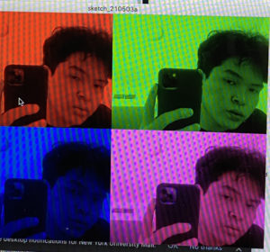
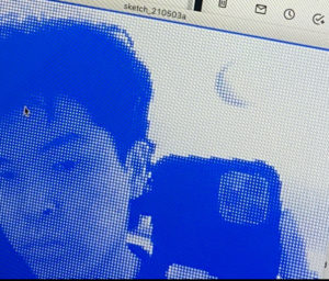
The main trick is in simplicity. The processing code consists of several stages of realities: starting from distortion, to alienation, to taking a visit to an upside world only to see thriple and frouple of you at the final stage. During this emerging and magical process, the spiral hypnosis adds up to the whole surrealistic moment that was intended to be recreated. The sonic unearthy sound of the motor contributes to making the experience more sensual and industrial.
MIRRORS
THE PROCESSING CODE
import processing.video.*;
import processing.serial.*;
Serial myPort;
int switcher = 0;
int cellSize = 5;
int duration = 155;
// Number of columns and rows in our system
int cols, rows;
Capture video;
void setup(){
  size(640,480);
  frameRate(20);
  cols = width / cellSize;
  rows = height / cellSize;
  colorMode(RGB, 255, 255, 255, 100);
  printArray(Serial.list());
  String portname=Serial.list()[1];
  println(portname);
  myPort = new Serial(this, portname, 9600);
  myPort.clear();
  myPort.bufferUntil('\n');
  video = new Capture(this, width, height);
  video.start();
  background(0);
}
void draw(){
  tint(256,256,256);
  background(0);
  if (video.available()){
    video.read();
    video.loadPixels();
  }
  if(switcher==0){
    for (int i = 0; i < cols; i++) {
      // Begin loop for rows
      for (int j = 0; j < rows; j++) {

        // Where are we, pixel-wise?
        int x = i*cellSize;
        int y = j*cellSize;
        int loc = (video.width - x - 1) + y*video.width; // Reversing x to mirror the image

        float r = red(video.pixels[loc]);
        float g = green(video.pixels[loc]);
        float b = blue(video.pixels[loc]);
        // Make a new color with an alpha component

        color c = color(r, g, b, 75); //make smth out of the last number using potentiometer

        // Code for drawing a single rect
        // Using translate in order for rotation to work properly
        pushMatrix();
        translate(x+cellSize/2, y+cellSize/2);
        // Rotation formula based on brightness
        rotate((2 * PI * brightness(c) / 255.0));
        rectMode(CENTER);
        fill(c);
        noStroke();
        // Rects are larger than the cell for some overlap


        ellipse(0, 0, 5, 50);

        popMatrix();
      }
    }
    //image(video,0,0);
  }
  else if(switcher == 1){
        background(0,0,255);

        for (int i = 0; i < cols;i++) {
      // Begin loop for rows
      for (int j = 0; j < rows;j++) {

        // Where are we, pixel-wise?
        int x = i * cellSize;
        int y = j * cellSize;
        int loc = (video.width - x - 1) + y*video.width; // Reversing x to mirror the image

        // Each rect is colored white with a size determined by brightness
        color c = video.pixels[loc];
        float sz = (brightness(c) / 255.0) * cellSize;
        rectMode(CENTER);
        fill(255);
        noStroke();
        rect(x + cellSize, y + cellSize, sz, sz);
      }
    }
    //scale(-1,1);
    //image(video,-width,0);
  }
  else if(switcher == 2){

    scale(-1,-1);
    image(video,-width,-height);
  }
  else if(switcher == 3){
  tint(256, 0, 0);
  image(video, 0, 0, width/2, height/2);
  tint(0, 256, 0);
  image(video, width/2, 0, width/2, height/2);
  tint(0, 0, 256);
  image(video, 0, height/2, width/2, height/2);
  tint(256, 0, 256);
  image(video, width/2, height/2, width/2, height/2);
}
  else{
    println("Switcher = 0 again");
    switcher = 0;
  }
}
void mousePressed(){
  switcher++;
}
This consisted of creating a final project for the class that would combine both Arduino and Processing to create an Interactive game or application.
Idea:
My initial idea consisted of creating an application that would have two principal phases. The first phase would be an interactive free play piano where the user could explore and play the piano as they wish. This first phase would include features such as recording something and playing the record. The second phase would consist of a game where a piano would be shown and notes would be falling. The user would have to press (or play) the piano according to the falling notes. However, unfortunately, the first phase of the game took me a lot of time and effort that I was unable to work on the second phase. In the end, my project consisted of a music instrument application with additional features.
Process:
Initially, I worked on creating a basic platform for the piano. First I decided to solely focus on the processing part and therefore I started by creating a piano where keys from the keyboard represented the tiles from the piano. After, I focused on the design of the piano (basic design) implementing the shape functions in Processing.
Then one of the main components of my project was the sound files uploaded. I found files online and downloaded them. However, while doing my project, I realized the files needed to be edited to improve the sound and functionality of my instrument. Then I focused on learning about the minim library within Processing which helped me with making the sound files work.
After finishing with the files, I started working on the additional features. These features took me more time than I expected. The features I included were recording a note, stop recording, deleting notes from the record, adding notes to different parts of the record, and playing the record. The recording part was complicated because I wanted to implement a way to allow for various notes to be recorded in one part and played at the same time. I was able to do this by using a 2-D array where one dimension would represent the part being played and the other would represent the note being played. After implementing these various features, I focused on possible areas of improvement. One example was a self-updating array where an array would be resized onc
e the number of notes passed the capacity of the array.
Then, I started focusing on connecting the Arduino and implementing the Arduino board. I used simple features from the Arduino but they certainly did add great ways to make the application interactive. The parts I used were the photocells, buttons, and the distance measuring device. I was just able to get a total of 4 photocells. These represented the tiles in the piano. Because I wanted to create a full piano and using only 4 notes did not help, I decided to use the distance measuring device. According to the distance measured, the piano would be changing location and therefore this would affect the notes being played by the tiles. Finally, the buttons were used to access the recording and playing part. One of the buttons recorded and stopped recording while the other played the recorded file. I could not add another button to represent the deleting part but this part can be performed with a keyboard key.
Finally, I focused on the design of the piano because I did not want to keep the application with basic rectangles and circles. I decided to draw and create all the designs including the tiles and backgrounds. This was done with several applications including Procreate, Affinity Designer, and Adobe Illustrator.
Challenges
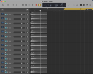
One of the main challenges encountered was in the sound files part. The files were really large in size and included parts that were not entirely necessary. Therefore I had to crop and edit some of the files because some of them were around a minute long. For notes on a piano, I did not need an entire minute. Since I wanted to shorten the file size and duration, I had to edit a total of 88 sound files in GarageBand. While doing the project I also realized that the beginning parts also needed to be edited. This was because, for the sound files, the actual sound did not start right away at the beginning of the file. This made several of my notes sound as if the application was lagging since the sound would be performed seconds after the tile was played.
Another challenge I encountered was with the part for the tiles. Since the piano consists of black and white tiles positioned differently across the piano. I had to create a way to recognize if a tile was black or white and according to this change the position of the tiles. This was challenging because although the piano tiles follow a pattern, the pattern is really complicated. For example, a pattern consists of 7 white tiles with 5 black tiles with black tiles separated as 2 and 3 tiles.
Finally, another main challenge I encountered was in the part where I had to connect the Arduino and Processing. I was not completely confident in using both together and therefore it took me some time to figure out some of the parts to connect this.
Areas of Improvement
There were several parts that I wanted to improve in my project. First, I want to possibly add new features to the free play piano. Some of the features in the piano are not functioning perfectly as I wanted although they are functioning. For example, for the selection of a specific part to add a note, this has to be selected AND deselected to be able to select another part. Also, I wanted to create a part where I could print or pop up a message for certain errors. For example, each “part” in the piano cannot contain more than 6 notes that are played at the same time. I wanted to print a message to represent this part when a user would try to record more than 6 notes in the same “part”. Another area of improvement was implementing the deleting button in the Arduino as mentioned in the Process part.
How the App works
The first part includes the initial part where the user must press the start button to begin the application
The 4 photocells represent 4 tiles in the piano. The keys to be played are represented by colored lines around the tile.
The red button is used to Start Recording. Once it is pushed, it must be pushed again to stop recording.
The Green button is used to play the record.
The distance measuring device represents the position of the keys represented by the photocells. When this device is altered, the position will be changed on the screen accordingly.
A user can select a specific part within a record to add a note in the part. To select another part, the user must deselect the previous part
A user can delete several notes at the same time by selecting the notes and pressing the ‘l’ key on the keyboard.
A user can also travel through the recording by using the ‘q’ and ‘w’ keys. The ‘q’ key is used to move the note part to the left while the ‘w’ key is used to move the key part to the right.
Conclusion
I was very proud to see my project completed because I dedicated a lot of time and effort to this. The code of the application resulted to be much longer and challenging than I expected. I really liked this project because I think it really represents my work. Starting from the ideas, the sound files, and the design, all components were created or edited by me. Although I could not implement my second idea, I really liked how the project turned out to be. I think it also includes an interactive part through the use of photocells and the distance measuring device. Overall, I really enjoyed working on this project and although it took me much more time and effort than I expected I think I was able to learn new skills and improve certain techniques within coding in general and applications such as Arduino and Processing.
For my final project idea i was unsure for a quite long time. Initially, it was an “art therapy app” as you can read in the previous post, but implementing some approaches in this app, i realised that in this particular program you are not creating new art pieces, but interact with existing ones. So I switched to this name.
Description
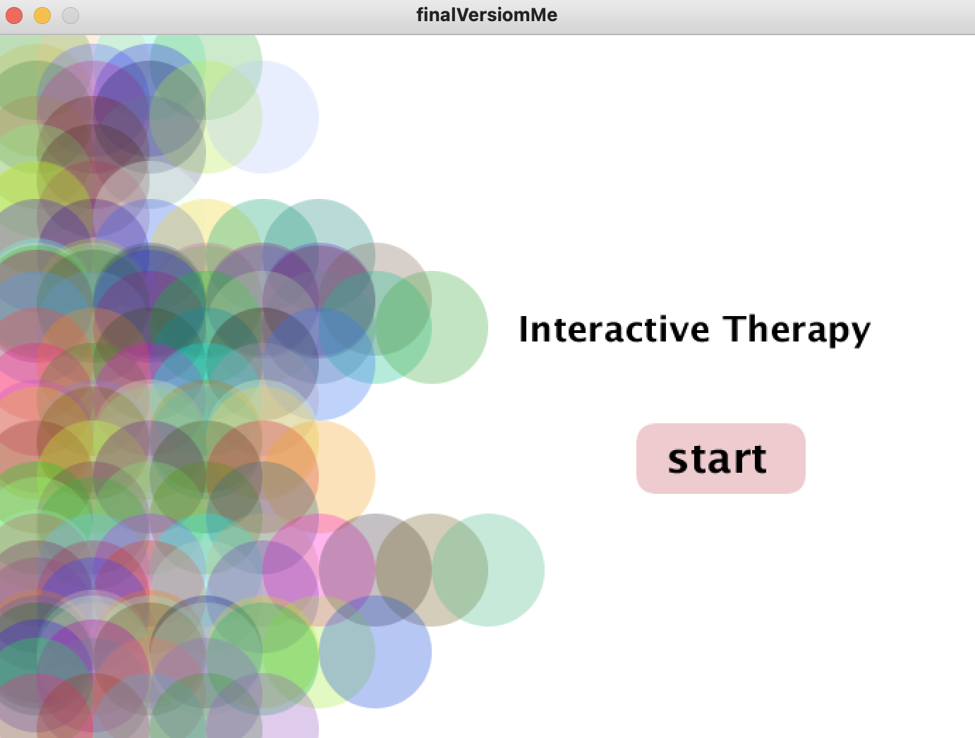
Welcome screen
App has first welcome screen with the button to start. Circle design is based on functions with some random statements, that is why each time program executes user gets different, a little bit unexpected design
Modes screen
In this part user gets a question “What do you feel?” and 3 options of the answer. There are different …. Inside each mode. Design is kind of similar to the previous tab to support the app style, but not copy the first idea. Based on the user’s choice screen moves to the next slide
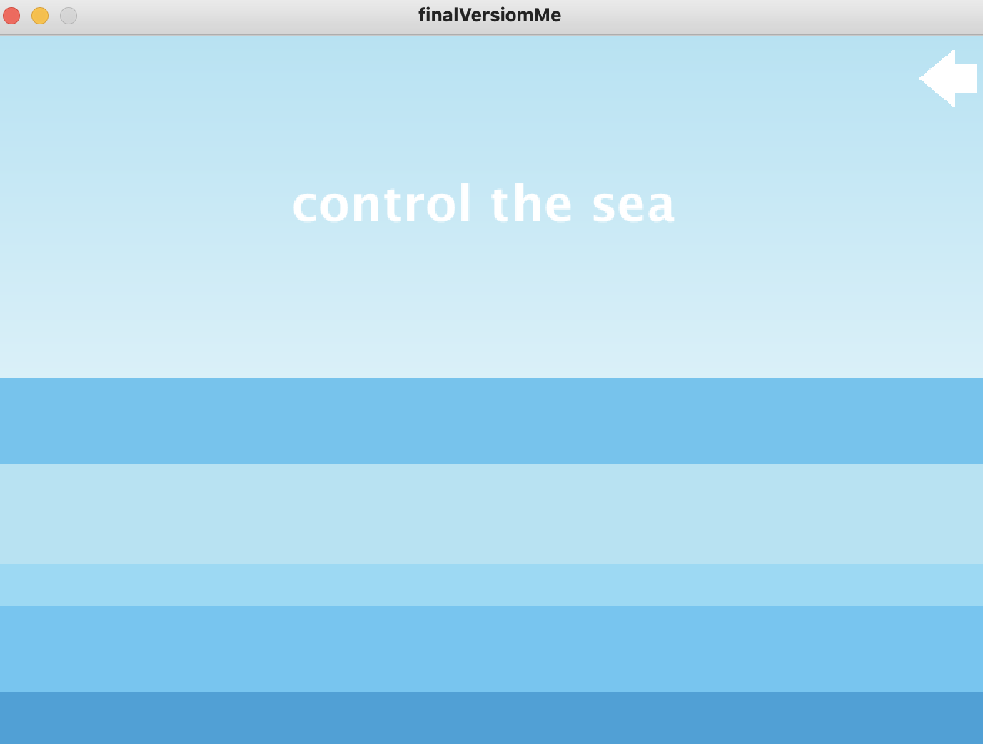
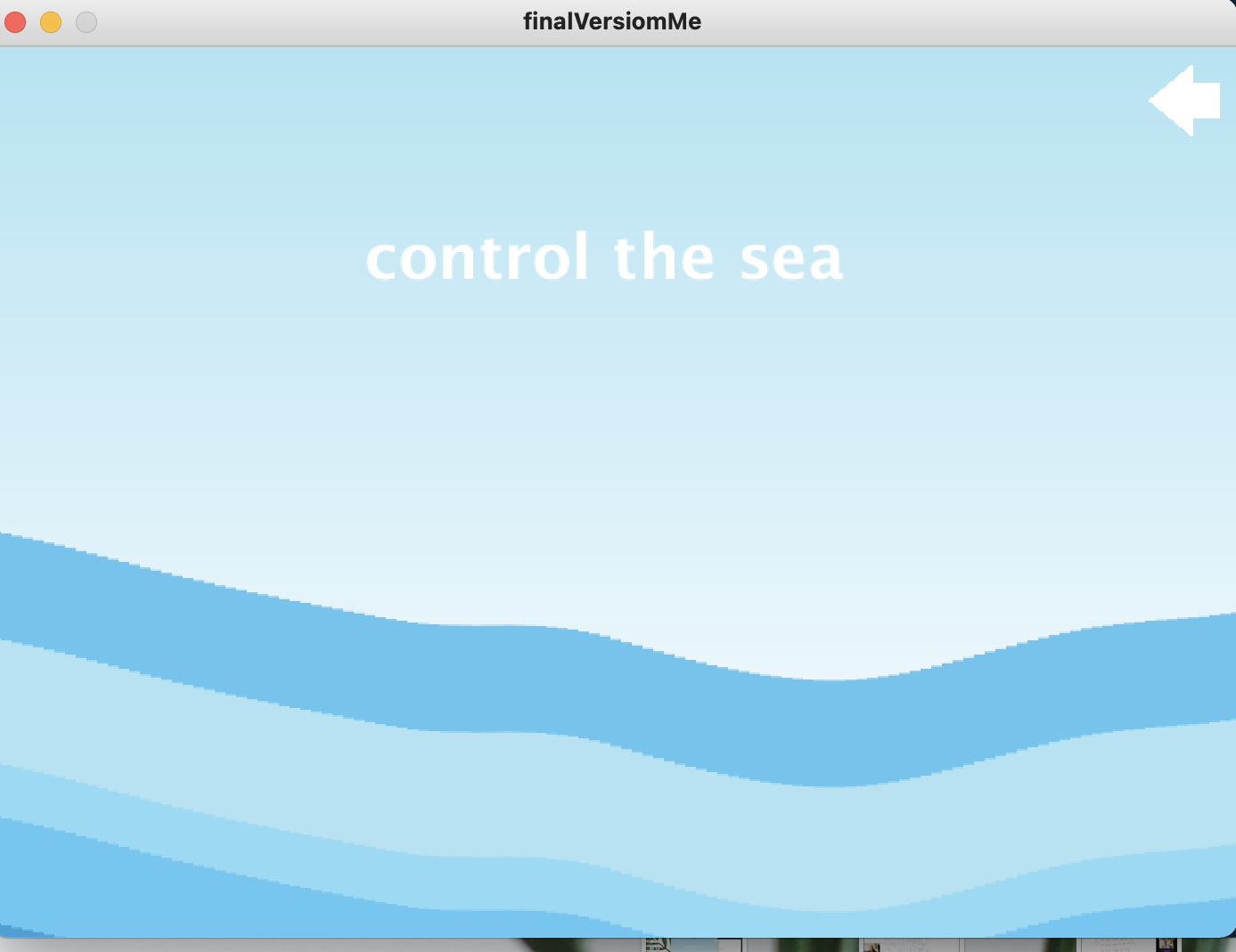
Anxiety mode
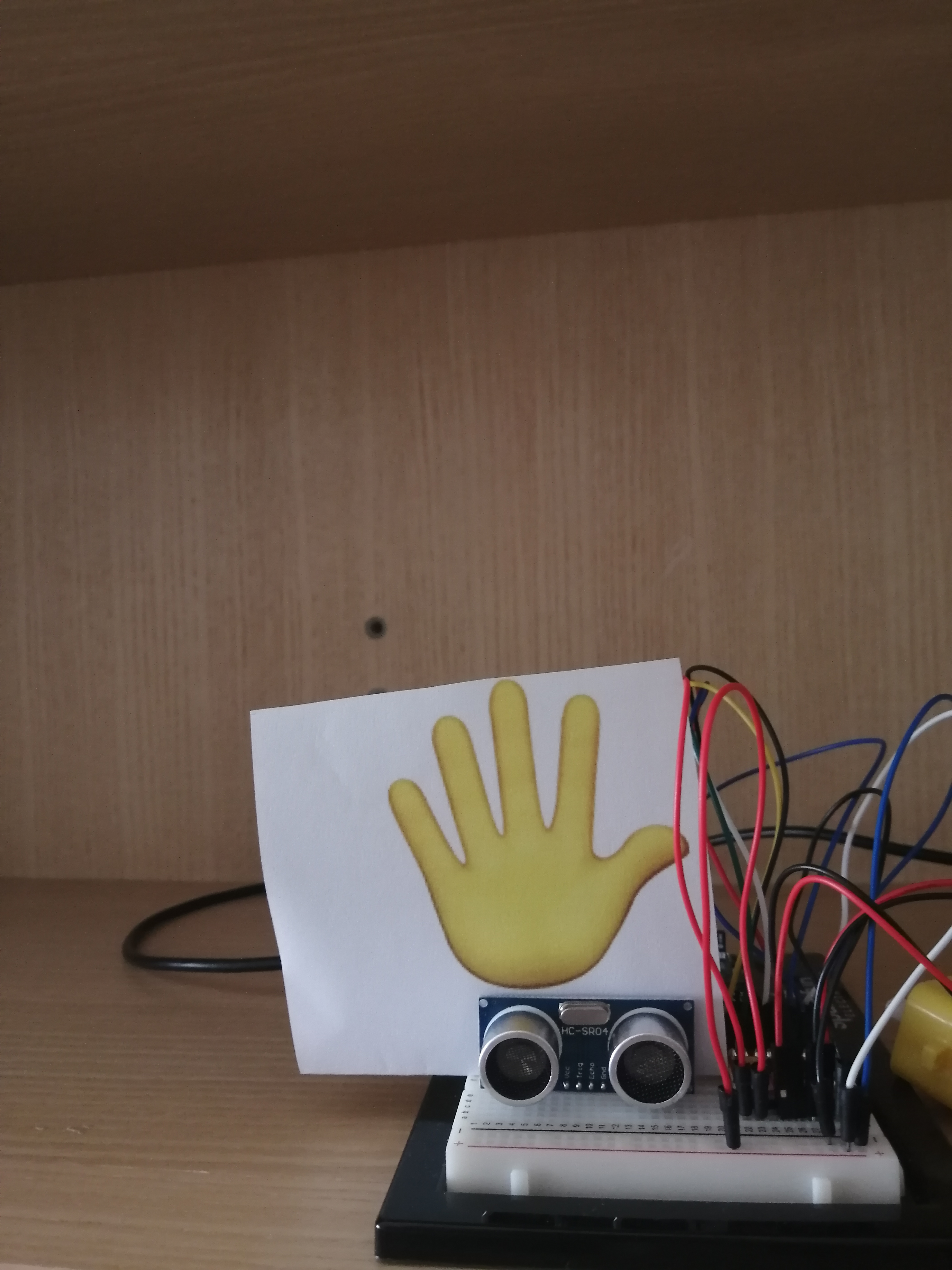
For this mode I picked up the sea as an image after tones of research of methods of art therapy/ help with mental problems and ….. . A lot of peoplefeel much better after some time spending near the churning sea, because sea is infinitely big and strong. Image of the sea gives people feeling of the happiness, satisfaction and peaceful state of mind. That it why I implemented some kind of meditation process here. You can imagine that you are the sea. And all your emotions proportional to the speed of the waves. You can use your hand to change the intensity of the power of the sea.
In terms of code i used rectangles and noise function (inspired by Ham
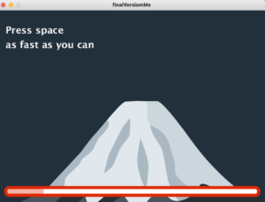
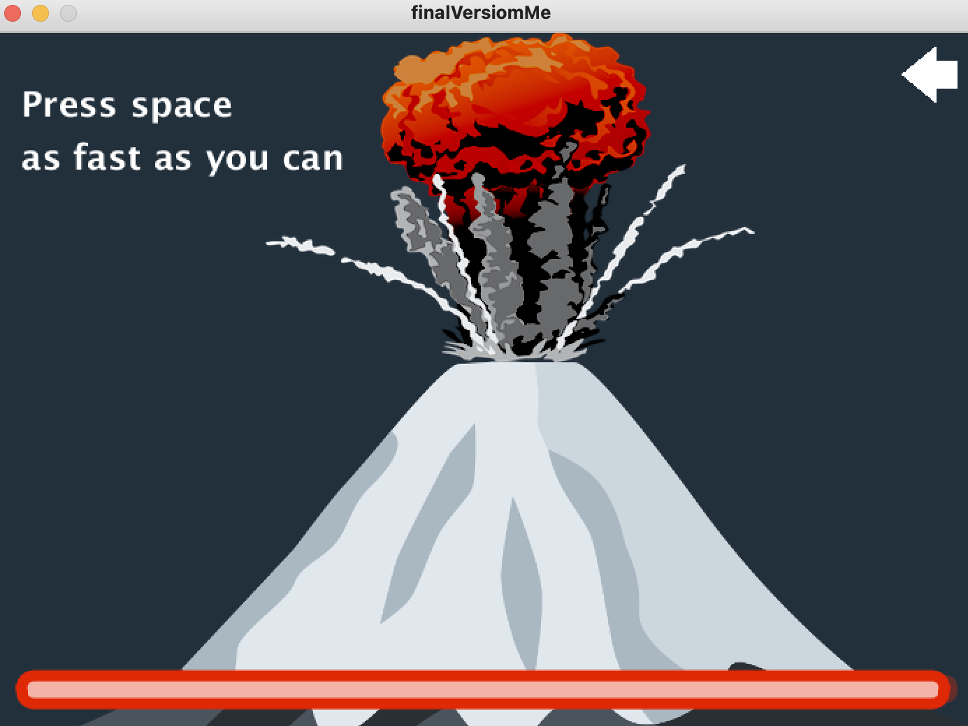
Anger mode
I was thinking about the visuals of this mode for a while. Expression of state of anger is different for each person, thus the image of the anger is different. I asked several people about this and got bunch of answers:
a) kettle emits a lot of steam
b)hammer breaks glass
c)active volcano
I stopped on the last idea of the volcano.
Happiness mode
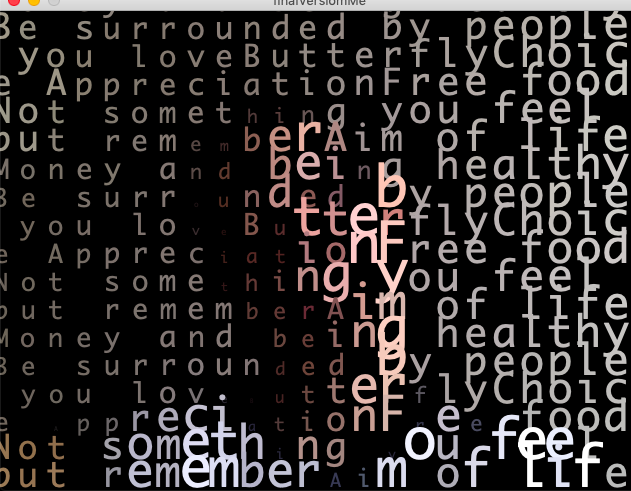
I used similar example as we did in class with camera recognition and self-text representation with the text
Arduino part:
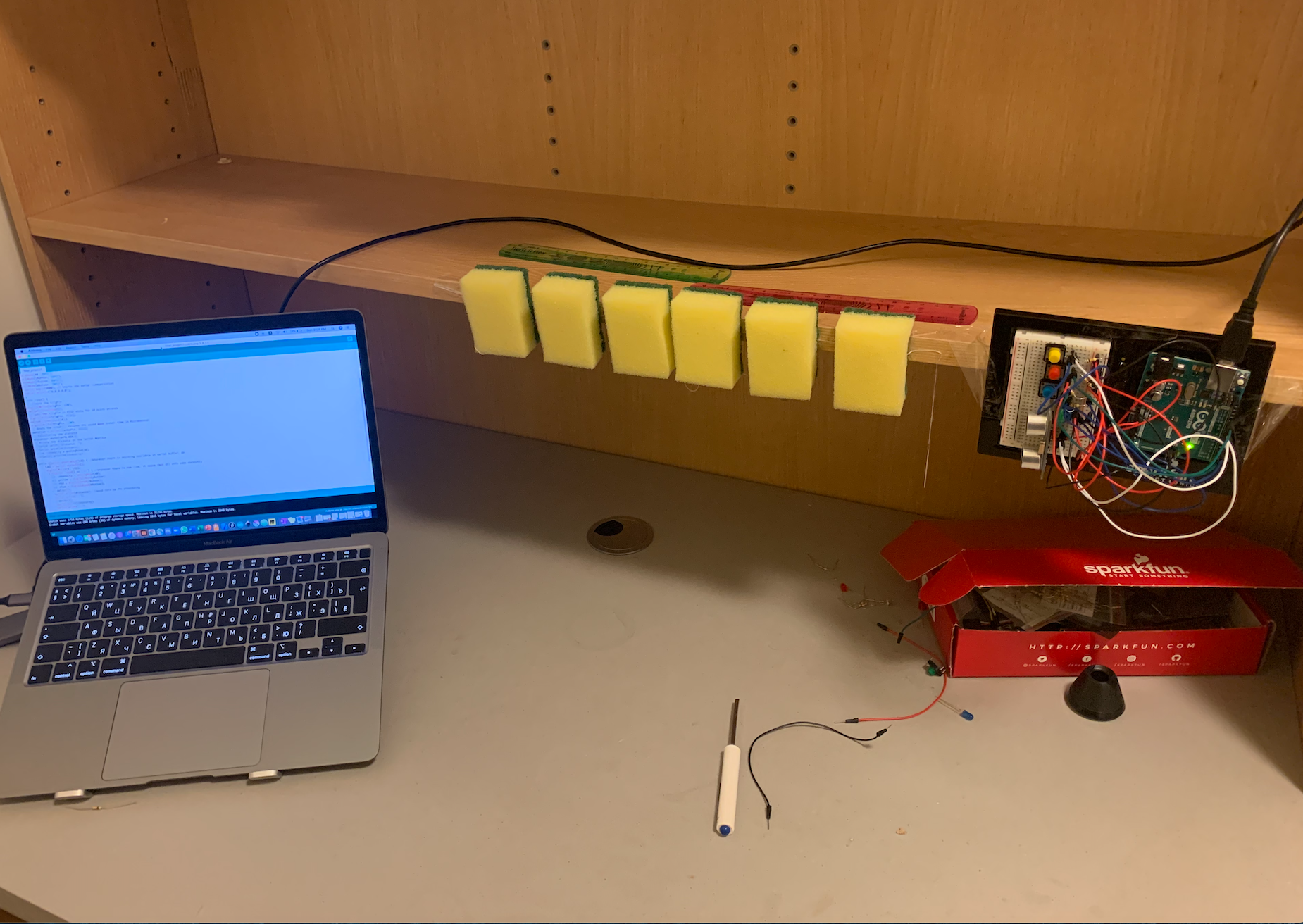
I used distance sensor and motors to make communication between processing and arduino. For distance i mapped the value and sent it to processing (to manage the sea). For motors i have a specific variable in processing, which depends on pressing the space(anger mode). This variable increases each time user presses space and go to arduino to make motor work
I wanted to beat something soft, so I decided on sponges. The only ones in the immediate vicinity were kitchen yellow sponges, and I used them. In order to attach them to the table, I needed to thread a thread through them and attach them with tape. To make the distance sensor at the same height with them, I had to spend another sponge and a lot of tape.
✅Changes
I moved the buttons in the Processing on the Arduino so that I wouldn’t move my hands from the top of the table while I was working. I also added an LED as an identifier of when the session started and when it ended.
I added a song to the background, as well as a final screen that suggests starting the session again.
Generative art spots don’t appear until the user selects a color, so I was able to make them transparent.
⚒ Code
Full code and all additional data are on my gitHub.
In my handshake from Arduino side I sent 5 values and received 1
Serial.println("0,0,0,0,0");
I added screenshot feature
void keyReleased() {
  if (keyCode == TAB) saveFrame(timestamp()+"_##.png");
}
There is a separate class for spots
Generative art letters code is partially taken from this website (thank you, Professor!)
💡Testing
Now my project is much more user-friendly, especially after previous week testing. During testing we were choosing the song that in our opinion suits this purpose and decided to use Linkin Park – Numb.
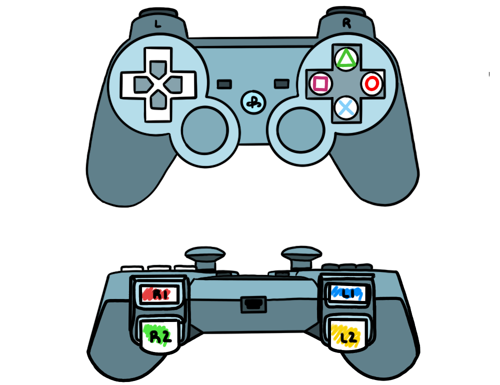
SpaceTrail is a game in which the user plays as a Space Artist by piloting a spacecraft along the screen and paint in a myriad of colors (different shades of blue, yellow, green red and a combination of all). The color of that the player is using is displayed on the Arduino spaceship through the LED lights, each lighting up in accordance the user input (except for the multicolor, which lights up all the lights).
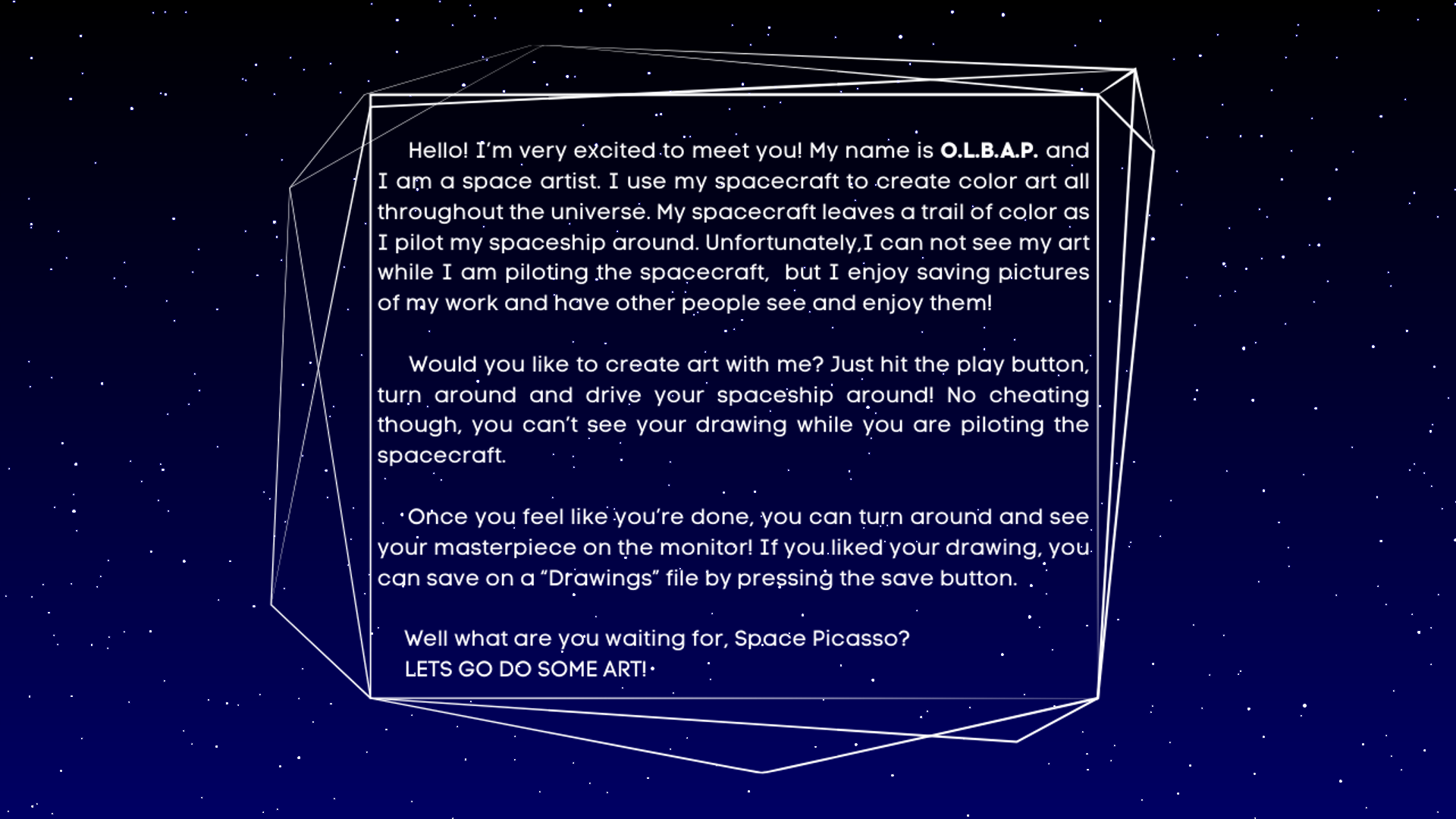
But there’s a trick to this game though: the player have their eyes on the spacecraft and the spacecraft only since if you were actually piloting a ship, you wouldn’t be able to see the trail you leave behind.
The spacecraft and menu are maneuvered through a PSP Controller which gets the user input and passes it to Processing and Arduino in order to move the spacecraft on the physical world and at the same time create the artwork on the screen.
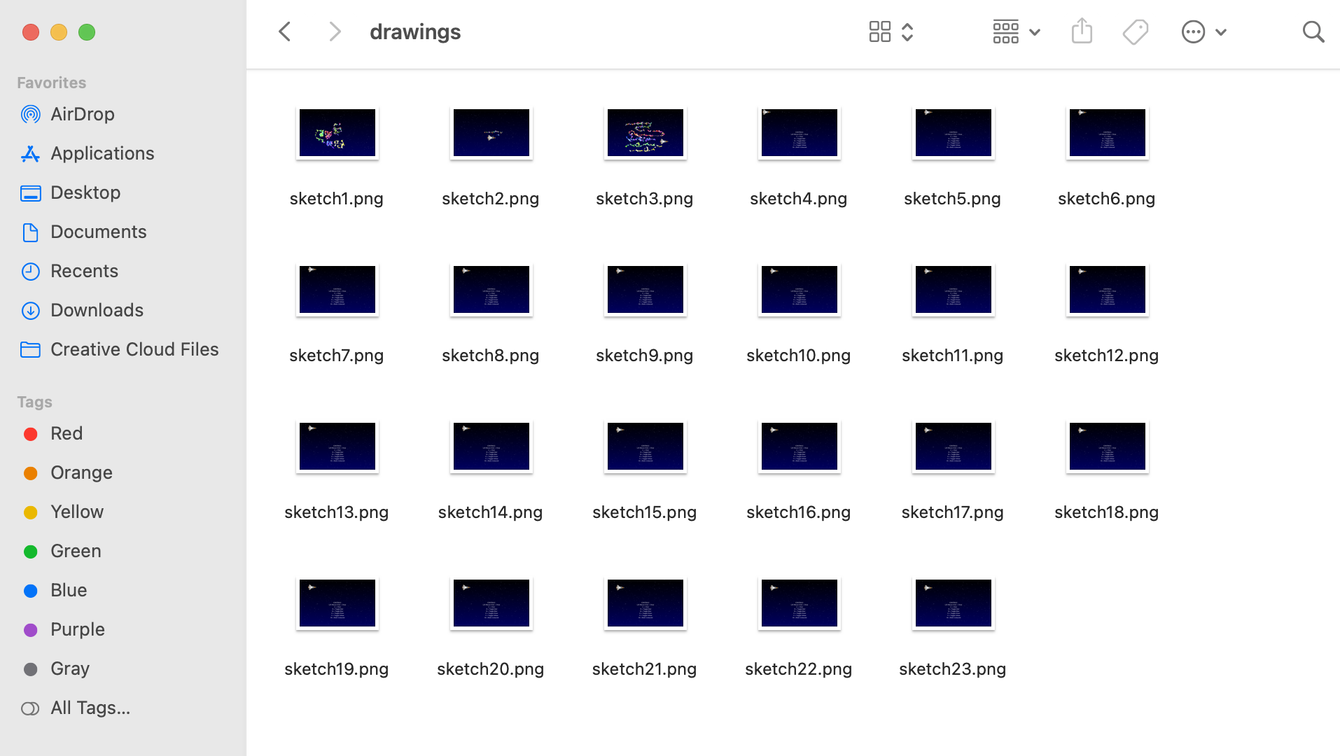
Once the player feels like they are done with their work, they can save it by pressing the SAVE button on the controller, which will locate the sketch on a folder within the program called “drawings”.
Process
Idea:
We had originally planned to make a car track simulator, however, we wanted to make something more creative and, whilst thinking of how we could incorporate the progress we had made previously (been able to get inputs from a controller using two special libraries in Processing and a Windows computer) to make something a little more spicy.
Armaan came up with the idea of using the car we created as a means to create art. Meanwhile, I wanted to leave the spatial intelligence test element in the project and alas, we came up with SpaceTrail.
We are extremely proud of our work. However, we did have to make a deal with the devil and sacrifice various campus cats (and our own sanity) to have this project ready.
Arduino and Serial Communication
Besides time consuming (to say the least) this project was also extremely painful and required a lot of trial and error, debugging and scratching out ideas to come up with new ones that actually worked. Though we had already made the controls for the car, which would be translated into the spaceship, we had a lot of problems with the serial communication, to the point were we had to re-think the type of input we wanted to get from the controller. We originally wanted to use the joystick as the input for the car movement (left, right, forward and backwards). Nonetheless, since this value had to be mapped, it decreased the speed of the car significantly as it took some time for the new values to reach the Arduino. Furthermore, the button states gave integers of 8 and 0 instead of the designated 1 and 0 booleans that configuration stated which affected the serial communication. Armaan was able to fix this by using the integers are the constrains for the conditions and the serial communication;. He spent two whole days (and most of the night) figuring out how to fix the problems we were having with the serial communication, I can attest.
A great part of our time was concentrated around the serial communication between processing and Arduino (specially after the LED light were incorporated in our model). It was very frustrating because one day the spaceship would be working perfectly, just for it to state (the next day) that it was having issues with variables sent by processing. Additionally, placing in the motors with the wheels was very difficult as the tape would sometimes fail and the wheel would go to the side, thus making movement harder. We solved it by adding an insane amount of 3M tape. It worked out at the end.
This is a video of Armaan placing the inputs of the controller to control the lights.
This is a video of how the car was working after adding the LED’s
Armaan’s hard work paid off because afterwards, we never had a problem with the serial communication (unless it was something like forgetting to plug in the Arduino Port).
Processing
For the processing, we created a stroke object that would be part of an array list that conformed the brush/trail of the spacecraft. Making the controls for the red, blue, green and multicolored options was not that difficult, however the yellow required more thinking since it is a combination of rgb colors.
This is a video of how they looked at the beginning.
We played around some more with the shapes, and once we were happy, we started working on a background that would represent the space theme of our project.
This is how it looked like:
We also changed things from this, like the color and the amount of stars. This became the background of our whole game.
We incorporated this background with the paint brush sketch to make this:
We also included commands to save the drawing and clear the sketch to start a new one.
To save the sketches without erasing the previous one, we create a table that save the number of the sketch, reloads it into the program when the game starts and adds one, to keep count of each sketch and be able to save them in the drawing folder.
We then added the commands for the spaceship to move around leaving a trail. This was very hard, specially because the movement of the spacecraft had to have the same logic as the one that Arduino used to command the motors of the spacecraft. It took Thais a lot of time. Indeed, too much time one could say. But alas, we made it. Thais was so tired however, because she didn’t had suhoor and it was already 5am, that she forgot to record this part. Shame on her.
We then combined both the Arduino and the Processing parts to create our functioning game!
We were so proud of our little guy. He was already drawing. They grow up so fast ;-;
That day we even changed its first wheels. 😭
The Menu
The menu was another very time consuming, but extremely satisfying element of our project. Thais designed the UI for the menu while Armaan place everything and created the logic for the transitions.
We also created a character named O.L.B.A.P, a space artist that would introduce the user to how the game works and what a space artist does.
This is some of the UI used:
Play UI Button
Exit Button HoverCharacter Information Button HoverController Instruction Button Hover
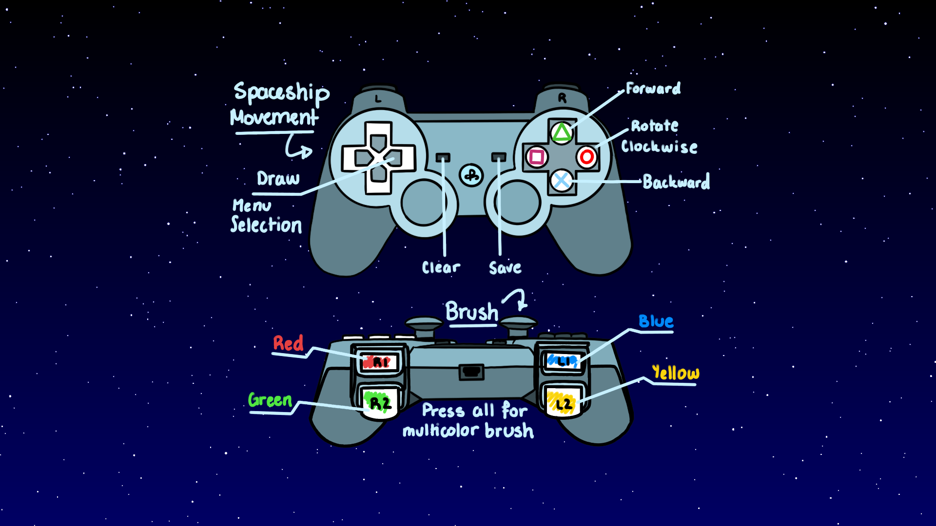
Controller UI for instructions page
We worked on various versions of the UI and their location in order to make the interface as aesthetic and welcoming as possible. For this, we tried multiple fonts, colors, hover elements and text frames.
The main menu ended up looking like this:
This is the character information page:
Controller Instructions Page
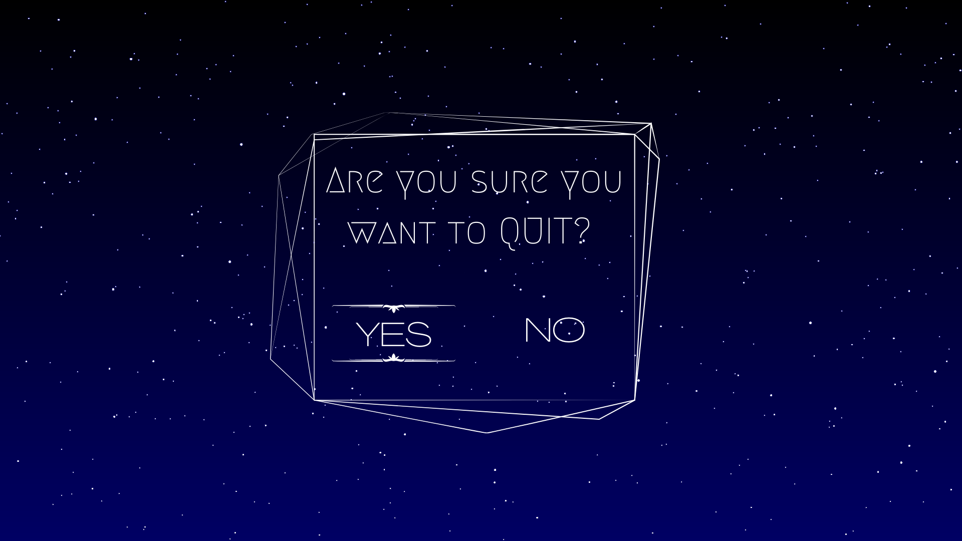
Exit Page
This is the test for the main menu:
Thais made this attempt to dress our little spacecraft with cardboard. However, we ended up discarding this design because the tape tampered with the motors, but we’ll put the image here so that you can laugh at this sad attempt of a spaceship. We even put stickers to it!
Final Product
Here we have a demo of our project, explained by my amazing partner Armaan.
This is a link to our Notion page were we have the references we used, the minutes of some of our meetings, a few images that we used as inspiration, as well as the several versions of our code.
So, I would like to start by saying, Cole and I have a working bomb! xD
Despite some external circumstances, we both have been able to finish this project successfully; we have a bomb, which works, explodes, and has a full mechanism to be diffused, along with full game aesthetics and UI. Honestly, it was a really fun project to work on. Kudos to Cole for being an amazing partner 🙂
Please go through our previous documentations to get an idea of how our project came along:
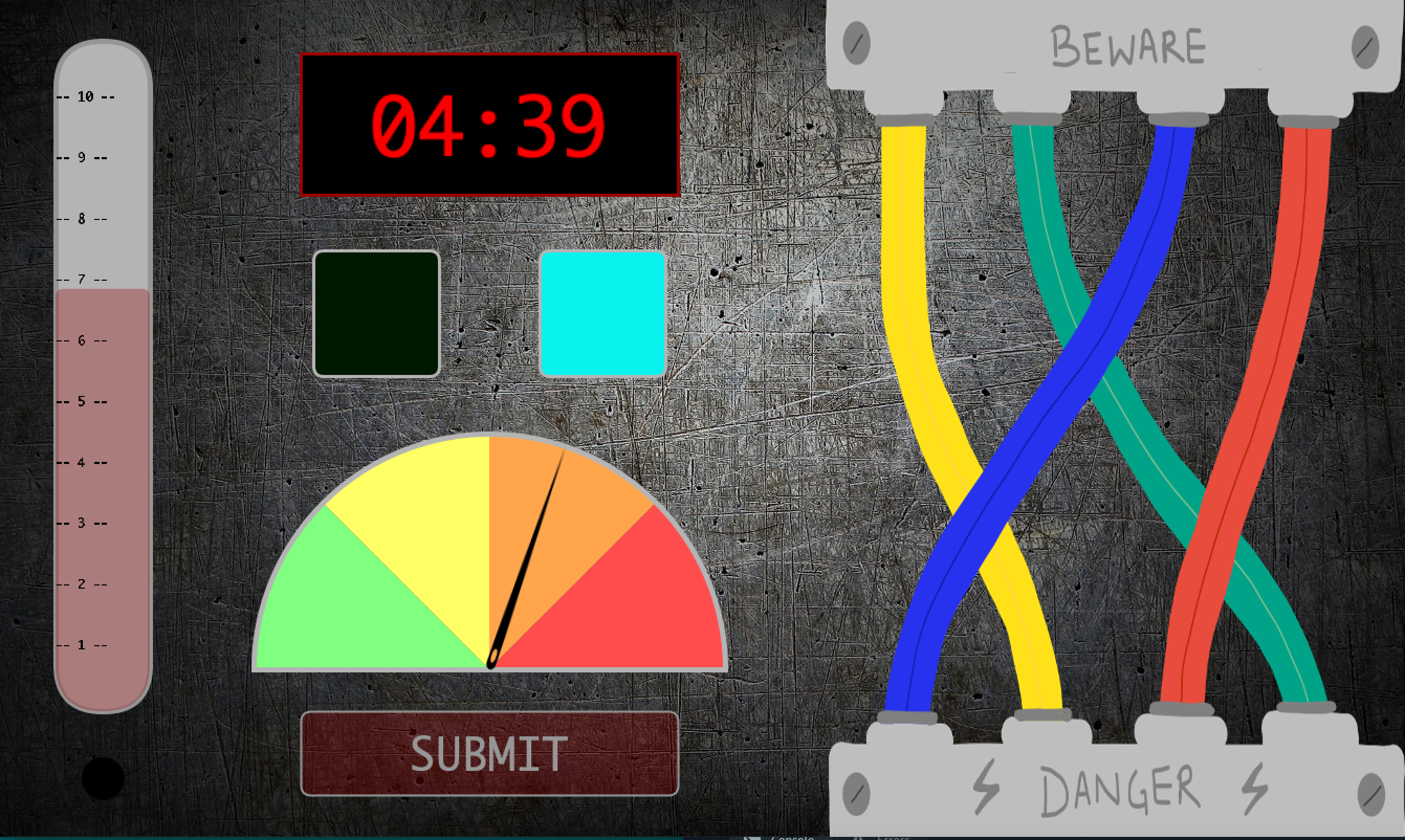
Since we were dealing with both Arduino and Processing, if something went wrong, or wasn’t working the way we expected it, it was really hard to find out where the problem was. It could have been in the circuit, or the Arduino code, or the handshake (arising from the difference in speeds of Arduino and Processing), or the Processing code/logic. So, we used a lot of println() statements to check if the input/output was being read from the Arduino and being correctly passed on to Processing. One problem we faced was on stage 3 when you have to replicate the LED patterns. It would set the bomb off sometimes even if the pattern was correct. After racking our brain on what was incorrect in the logic of our code, we realized that the problem was with the discrepancy in the speed of Arduino and Processing (even after establishing the serial communication) and not our code. Processing wouldn’t read all buttons pressed on the Arduino every time. When we printed these out, we realized where the problem was. This resulted in the addition of a small flashing light on the Processing screen on the bottom left corner to indicate which button color was pressed and read by Processing. If that light doesn’t flash, that means the button input wasn’t read. This proved to be a very important signifier.
Making it a bit harder
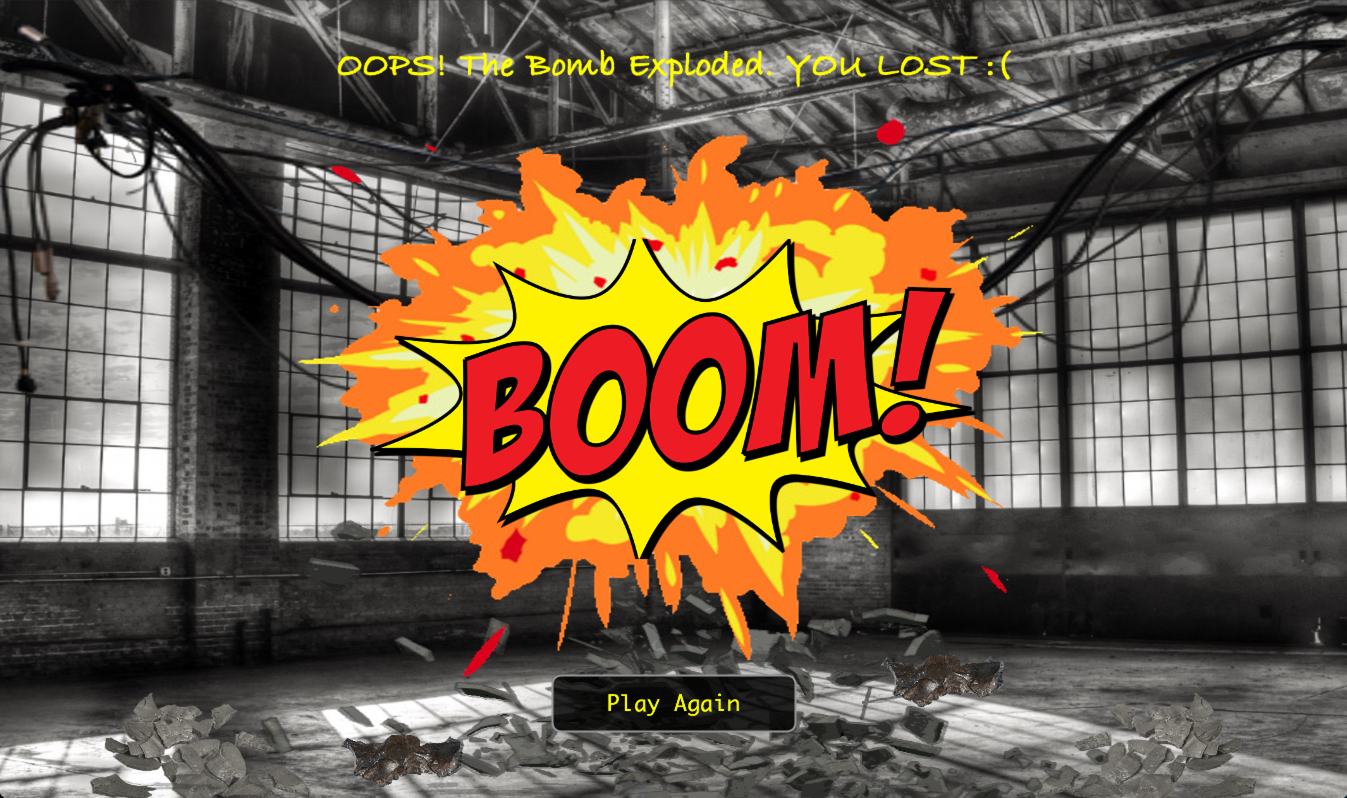
So, we coded our program to wait for specific inputs at each stage. But, what if a user by mistake, presses something Arduino/Processing is not waiting for at a specific stage such as a button when submit was expected? Since it is a bomb, ideally it should go off if something incorrect is done. So, to make the game harder and interesting, but not letting the bomb go off at every wrong input, giving the user a little flexibility to play around and have fun, we decided to have 2 checks. 1) Make the bomb explode if an incorrect input is given from one of the input methods the particular stage is waiting for, 2) reduce the time left by 10 seconds if an incorrect input is given from a wrong input method. In our program, you can record an input by either pressing one of the four buttons on the Arduino screen or the submit button on the Processing screen for the distance and potentiometer. If an input is expected from the Arduino button and submit button is mistakenly clicked, it reduces the time. However, if a yellow Arduino button was expected, but a red one was pressed, then the bomb goes off.
Additional Touches and User Experience
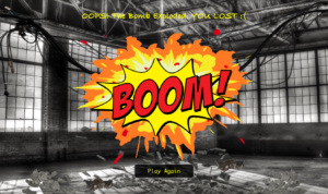
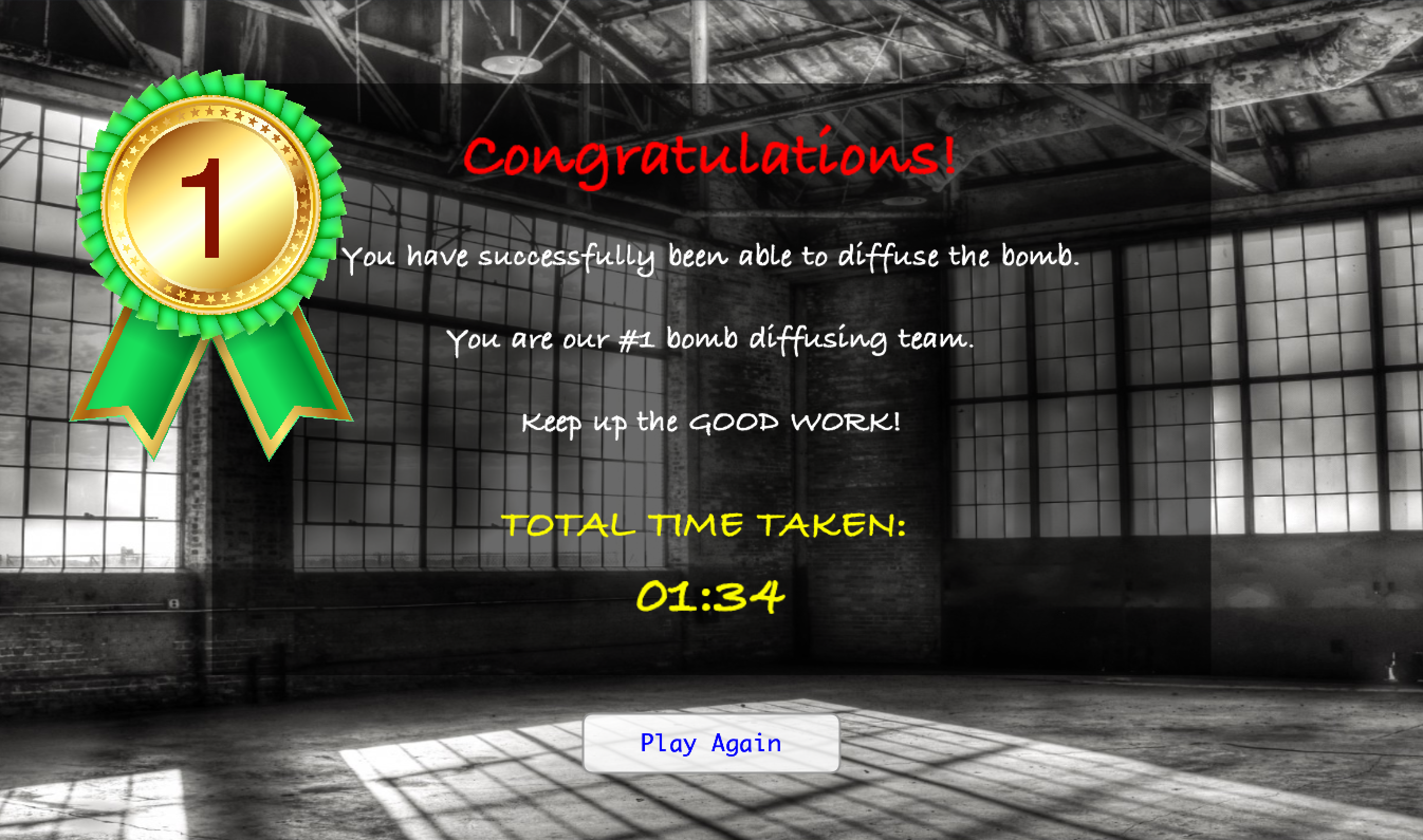
We decided to add sounds for user experience and specific feedback to the user. For example, it was essential to indicate to the user when their time was reduced. So we added a sound for this to the Processing program. Then, of course, you want to hear an explosion right when the bomb goes off? Should look real. So, we decided to add a sound to both our end screens – if you win or lose. Finally, we also have the best sound of all, the bomb being defused and the game being won!
Game Design and UI
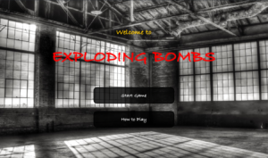
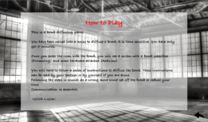
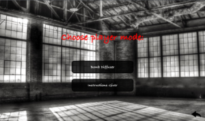
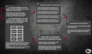
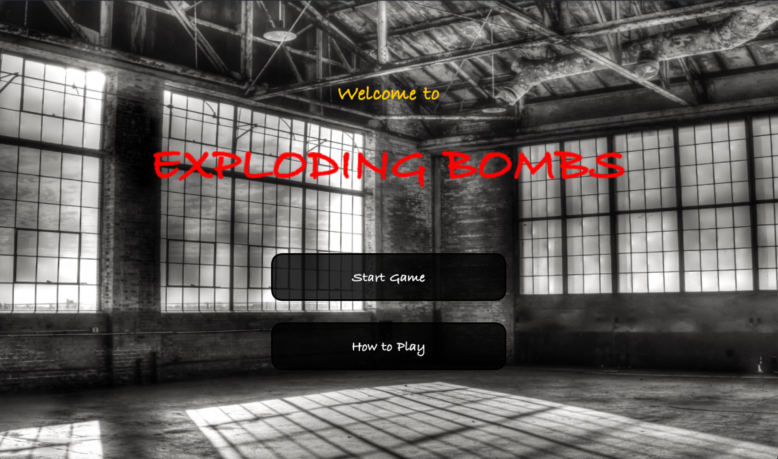
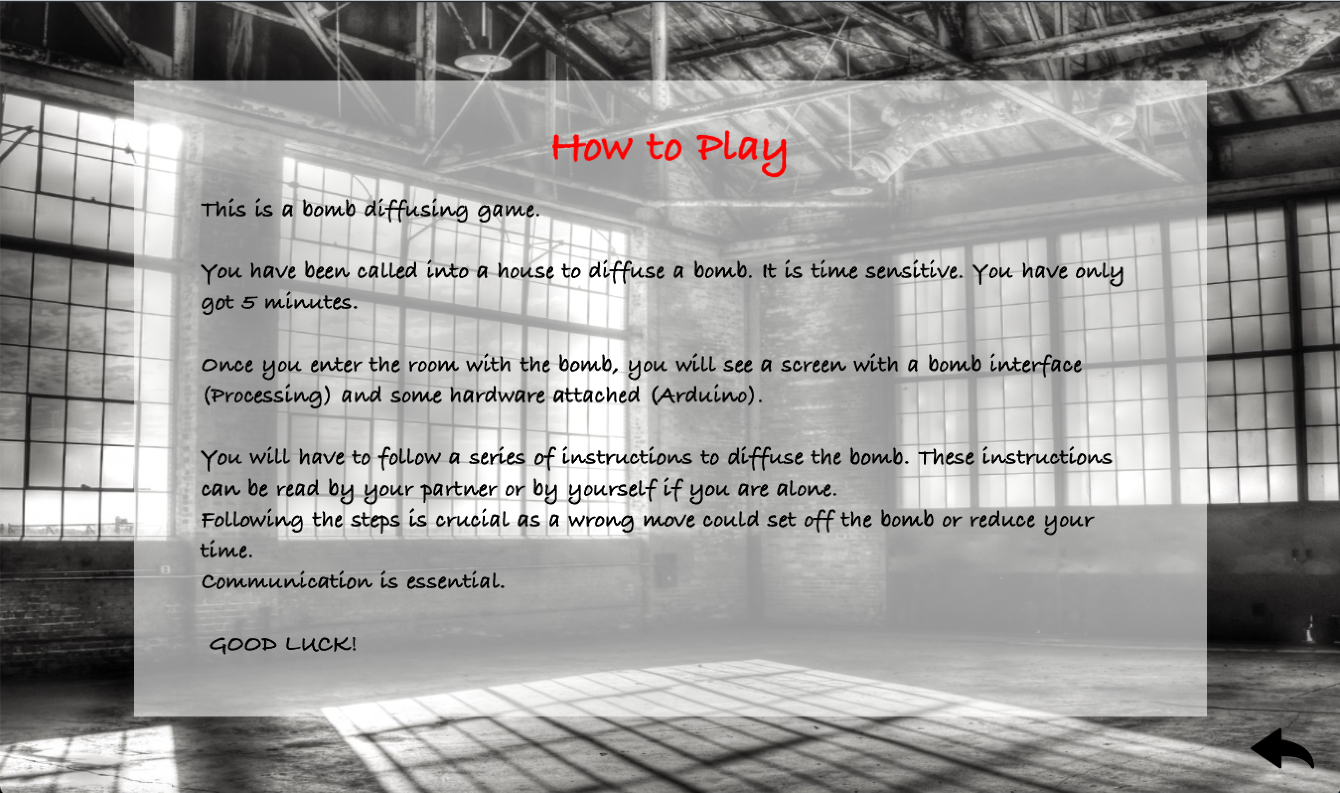
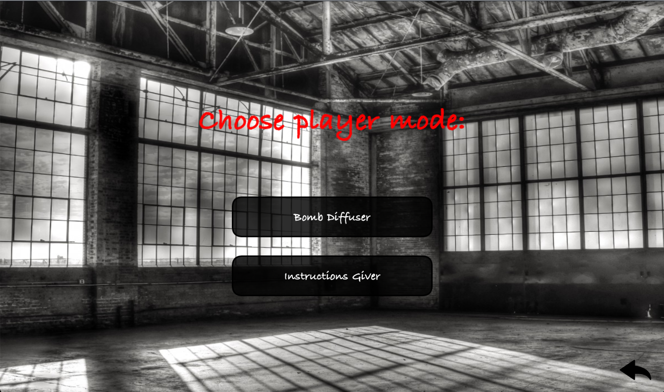
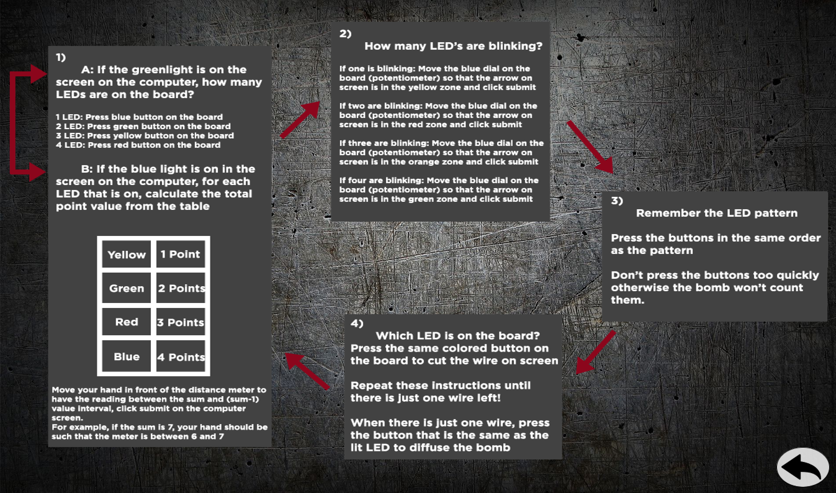
We made a total of 6 screens for the whole game (the last one having 2 parts) – 1) A start/menu screen, 2) a ‘how to play’ screen, 3) a player mode choosing screen which would navigate to the game screen or bomb instructions screen, 4) bomb instructions screen, 5) the game screen, 6) end screen: win screen and lose screen.
Honestly, UI takes quite some time to implement because of all the design, color choices, etc. We even added back buttons for easy navigation and a ‘play again’ button if the user wishes to go back and replay the game, switch roles with their partner, etc.
Our game is also designed in a way that it can be 2 players or 1 player. For one player, all you would have to do is keep a screenshot/printout of the bomb instructions printed out and handy.
See a video for each in the end!
User Testing
Shoutout to all our friends who played the game. Several nights we had friends trying out the game which helped us make several changes. We found that the instructions needed to be written in a more straightforward manner about the flow of the game, the non-technical language used to describe the Arduino, as well as some limitations in what Processing was handling.
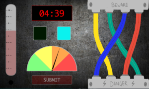
Processing/Arduino communication: As Processing is more powerful running on a laptop than on a computer, all the logic about which lights are on is done via Processing. Every handshake involves sending 4 boolean variables, one for each light, as well as two bomb state variables (exploded or defused) to the Arduino. Arduino receives this information, lights up the passed LEDs or goes into an exploded/defused state. Arduino then returns the state of each button, the distance meter reading, and the potentiometer back to Processing.
Random LED: Each time the bomb goes into a new phase, the variables for each light are randomized within the constraints of that round. For example, in the round where a random amount of LEDs flash, first a random number 1-4 is chosen and then that many random LEDs are flashed.
Button Press/Used: Since Processing is running at 60fps(if we are lucky) and Arduino is running at a much faster rate, we had to add a variable that would determine if a button is being pushed, similar to the function mouseClicked(){}. We created a boolean variable that would be set to true whenever a button was recorded being down and back to false when released so we could keep track between rounds and extra inputs were not recorded.
Bomb timer: Processing gives current time in milliseconds using the function millis(). We used milliseconds as a unit to do all time calculations – recording start time of game, getting the current time, calculating time elapsed and time left, periodically updating those and also noting the final time taken to diffuse the bomb for the end screen. However, we wanted the time to be displayed in the usual format of minutes and seconds, so we made a convert time function to display it in the appropriate format.
Overall I am really happy with how our project came out. We went from a rough idea inspired by a VR game to a fully formulated and functioning team building game that really utilizes both the strengths of Arduino and Processing. Shreya was a great partner and we made this come together through great teamwork.
Here is our previous documentation that can show how we have come along
Since we were dealing with both Arduino and Processing, if something went wrong, or wasn’t working the way we expected it, it was really hard to find out where the problem was. It could have been in the circuit, or the Arduino code, or the handshake (arising from the difference in speeds of Arduino and Processing), or the Processing code/logic. So, we used a lot of println() statements to check if the input/output was being read from the Arduino and being correctly passed on to Processing. One problem we faced was on stage 3 when you have to replicate the LED patterns. It would set the bomb off sometimes even if the pattern was correct. After racking our brain on what was incorrect in the logic of our code, we realized that the problem was with the discrepancy in the speed of Arduino and Processing (even after establishing the serial communication) and not our code. Processing wouldn’t read all buttons pressed on the Arduino every time. When we printed these out, we realized where the problem was. This resulted in the addition of a small flashing light on the Processing screen on the bottom left corner to indicate which button color was pressed and read by Processing. If that light doesn’t flash, that means the button input wasn’t read. This proved to be a very important signifier.
Making it a bit harder
So, we coded our program to wait for specific inputs at each stage. But, what if a user by mistake, presses something Arduino/Processing is not waiting for at a specific stage such as a button when submit was expected? Since it is a bomb, ideally it should go off if something incorrect is done. So, to make the game harder and interesting, but not letting the bomb go off at every wrong input, giving the user a little flexibility to play around and have fun, we decided to have 2 checks. 1) Make the bomb explode if an incorrect input is given from one of the input methods the particular stage is waiting for, 2) reduce the time left by 10 seconds if an incorrect input is given from a wrong input method. In our program, you can record an input by either pressing one of the four buttons on the Arduino screen or the submit button on the Processing screen for the distance and potentiometer. If an input is expected from the Arduino button and submit button is mistakenly clicked, it reduces the time. However, if a yellow Arduino button was expected, but a red one was pressed, then the bomb goes off.
Additional Touches and User Experience
We decided to add sounds for user experience and specific feedback to the user. For example, it was essential to indicate to the user when their time was reduced. So we added a sound for this to the Processing program. Then, of course, you want to hear an explosion right when the bomb goes off? Should look real. So, we decided to add a sound to both our end screens – if you win or lose. Finally, we also have the best sound of all, the bomb being defused and the game being won!
Game Design and UI
We made a total of 6 screens for the whole game (the last one having 2 parts) – 1) A start/menu screen, 2) a ‘how to play’ screen, 3) a player mode choosing screen which would navigate to the game screen or bomb instructions screen, 4) bomb instructions screen, 5) the game screen, 6) end screen: win screen and lose screen.
Honestly, UI takes quite some time to implement because of all the design, color choices, etc. We even added back buttons for easy navigation and a ‘play again’ button if the user wishes to go back and replay the game, switch roles with their partner, etc.
Our game is also designed in a way that it can be 2 players or 1 player. For one player, all you would have to do is keep a screenshot/printout of the bomb instructions printed out and handy.
See a video for each in the end!
User Testing
Shoutout to all our friends who played the game. Several nights we had friends trying out the game which helped us make several changes. We found that the instructions needed to be written in a more straightforward manner about the flow of the game, non-technical language used to describe the Arduino, as well as some limitations in what Processing was handling.
Processing/Arduino communication: As Processing is more powerful running on a laptop than on a computer, all the logic about which lights are on is done via Processing. Every handshake involves sending 4 boolean variables, one for each light, as well as two bomb state variables (exploded or defused) to the Arduino. Arduino receives this information, lights up the passed LEDs or goes into an exploded/defused state. Arduino then returns the state of each button, the distance meter reading, and the potentiometer back to Processing.
Random LED: Each time the bomb goes into a new phase, the variables for each light are randomized within the constraints of that round. For example, on the round where a random amount of LEDs flash, first a random number 1-4 is chosen and then that many random LEDs are flashed.
Button Press/Used: Since Processing is running at 60fps(if we are lucky) and Arduino is running at a much faster rate, we had to add a variable that would determine if a button is being pushed, similar to the function mouseClicked(){}. We created a boolean variable that would be set to true whenever a button was recorded being down and back to false when released so we could keep track between rounds and extra inputs were not recorded.
Bomb timer: Processing gives current time in milliseconds using the function millis(). We used milliseconds as a unit to do all timer calculations – recording start time of game, getting current time, calculating time elapsed and time left, periodically updating those and also noting the final time taken to diffuse the bomb for the end screen. However, we wanted the time to be displayed in the usual format of minutes and seconds, so we made a convert time function to display it in the appropriate format.