This project aims to create a small-scale self-driving experience. It implements a machine-learning module that captures user hand gestures for steering and a foot pedal for accelerating, braking, and stopping. A user controls the car by imitating the driving steering wheel movements in real life in front of a computer camera and engaging the pedals with the foot. However, that isn’t implemented yet.
Implementation
To make this possible and achieve a near-real-life driving experience, we implemented a machine learning module that uses a camera to capture a user’s hand gestures. This machine learning module is implemented in p5.js and is synced with the pedal and the robot via Bluetooth; however, that isn’t implemented yet. Regardless, a network is created between the robot and the pedals for user control.
From interacting with the code for the DC motors, it seems the maximum attainable speed is 500, which is relatively slow. However, we implemented a code that prevents the robotic car from crashing. When a user accelerates towards an obstacle, the robot stops, scans 180 deg away from the obstacle, and then moves back. In some cases, it scans and moves toward a direction devoid of obstacles.
We also installed an ultrasonic sensor to help avoid obstacles. The distance sensor is fastened to a servo motor to enable free rotation. This was particularly important because we implemented an algorithm that scans surrounding areas for obstacles and moves the robotic car in a direction that is devoid of obstacles.
Displayed here is the code defining the DC motors and other dependencies.
Our proudest achievement so far is the implementation of the machine learning module.
Also, the algorithm that checks for obstacles in a smart way and prevents users from crashing is a feat we’re most proud of. We believe this is implementation in real life could save lives by preventing vehicular accidents.
Aspects we can improve on in the future.
The most significant aspect of the project we believe would impact the world if worked on is the obstacle sensor that prevents the car from crashing. We believe if this is worked on on a larger scale, it could be implemented in cars to help reduce road accidents.
Regardless, we also believe we can engineer a reverse the obstacle-sensing algorithm to create an algorithm that could detect cliffs and pot-holes, and dangerous empty spaces on roads to ultimately reduce road accidents.
Pac-Xon Premium, extended from Pac-Xon Deluxe – a Pac Man inspired game, was one our team member’s childhood favorite. Pac-Xon Deluxe, the original game, is fairly simple with numerous levels with increasing difficulty. The experience of the game seems to be fairly decent and easy at first, however as you start completing the levels it gets interesting. However, the increase in difficulty is very gradual, such that you may lose interest in playing further due to repetitiveness, and even the most difficult level may not present that great of a challenge to you. Additionally, the graphics of the game were classic but old, and we believed we could associate a modern touch and feel to the game and produce a revamped and customized version of it.
The gameplay may seem pretty simple at first glance, so we thought it would be something fairly simple to code. However, as we progressed and laid out the logic and technical aspects that were required for even the smallest of details in the game, we realized that it involves a relatively complex algorithmic approach, rather than using just simple Object Oriented Programming coupled with Javascript Basics. Since we wanted to take the game a step further, we wanted to ensure that almost all objects interact amongst each other, all of which was to be wrapped in the complexity of a tile-based game!
We initially proposed a Box Musician Game that was intended to be a rhythm game with a physical controller and notes to play. Though, during the implementation process we have decided to move away from the idea of making a project all about the music and use the physical controller for the Chill Adventure game to move across different game levels instead. The concept of moving across different levels while avoiding threats was also inspired by Vladimir’s midterm project.
Interaction design:
The main components behind interaction with the player are the physical board and the physical controller both made of wood. The controller is moved across the board and this movement is then reflected on the game screen. Player needs to use their hand to navigate through their game experience.
The concept behind using Arduino:
As proposed, we are using 2 ultrasonic sensors to detect the change in the position of the physical wooden controller and make the movement reflected in the p5js game screen. We use the speaker to play tones of different frequencies upon the collection of coins and we use a servo motor to rotate frequently to signal the unfortunate event of the player’s death.
p5.js code implementation handles most of the game design and implementation. Code implementation includes movement across the screen, collision detection, and change of screens when the player has completed a certain level to move to the next one/finish the game, with the possibility to restart the experience. p5.js handles graphics of the game, shapes, text displays, etc. p5.js overall uses the Entity-component system design pattern, which you can read more about in Vladimir’s Midterm Blog Post
The game has several “Scenes”: The Menu scene, the Play scene (the levels), and the End scene. Each scene is completely separate from the others and contains its own logic. The Play scene receives a level (a list of strings) as its parameter and loads every part of the level. This includes walls, tiles, the player, and NPCs. You can see the levels in the folder ‘levels’: ‘level1.txt’, ‘level2.txt’, and so on. These were generated using a Helper Level Generator Script (.py).
For the entities in the levels, we use sprite sheets and even animate some of them (e.g. coins). Also, we implemented an NPC AI that follows the player, as well as a random movement AI that uses Perlin noise to decide the velocity at each moment.
We paid special attention to designing the levels so that they are not too frustrating to complete, considering our unconventional play method. Doubly so after the user testing.
Arduino sends X and Y coordinates mapped from the readings of ultrasonic sensors to p5.js so that position of the player is accurately reflected on the game screen
p5.js send to Arduino info that the player has virtually died and this would trigger the action of rotating servo motor – with the goal of making sound.
p5.js send to Arduino info about the tone and frequency to play from speaker whenever a coin is collected, or similar.
Some of the initial challenges we faced involved tracking the position of the controller. We first thought about placing two sensors in parallel and using the space between their waves to create a coordinate plane, like they do here: 2D tracking using Math. However, after trying this out, we found that we would need a very big area (more than 2 meters squared) and it was still very imprecise and buggy. Therefore we changed our approach to use two sensors which are perpendicular to each other, one tracking X and one tracking Y position.
The final Arduino implementation of how tracking position works in the project is presented below. X and Y from trackPosition () would be sent to p5.js for further processing.
Code snippet from the communication of p5.js with Arduino from the p5 side:
// Send answer to Arduino.
const isPlayerAlive = this.entityManager.get("player").length > 0;
const collectionDelay = 0.3 * FRAME_RATE;

if (this.shouldSendPlayerDiedSignal) {
  // Send death signal.
  this.shouldSendPlayerDiedSignal = false;
  this.game.sendArduino("2\n");
} else if (
  this.lastNpcCollectionFrame + collectionDelay >
  this.currentFrame
) {
  // Send tone.
  const t = this.currentFrame - this.lastNpcCollectionFrame;
  const f = floor(map(t, 0, collectionDelay, 200, 1500));
  this.game.sendArduino(`3,${f}\n`);
} else {
  // Send OK signal.
  this.game.sendArduino("1\n");
}
The last challenge was to make sure that activation of the rotating servo motor, playing tones from the speaker, and tracking position worked well together. The adjustments were made for use of delay() to not make one operation prevent other ones from working properly for the purposes of the project. To check the final implementation in Arduino, you can refer to the Arduino Code
Embed sketch:
What are some aspects of the project that you’re particularly proud of?
We’re proud of how we made our unconventional controller. Our controller may initially be frustrating to play with, but there is a learning curve, and smooth precise movements are possible with enough practice. We’re also happy that we created an interesting enough, although possibly frustrating, game to play and keep the user’s attention.
Though, we should admit we found the experience of making the game slightly weird, unconventional and to some extent frustrating rewarding and creative in a sense. There are a lot of other games which are easy and relaxing, but for this project, we felt we would want our players to get challenged and driven to succeed through all the tough walls, confusing moves, and undefined threats they face in the game.
What are some areas for future improvement?
A bigger model can be made with better ultrasonic sensors and a larger area. This would enable easier and smoother control. Also, the possibilities in p5 are endless. We can expand our game with new levels, create a completely different type of game, or even create something that’s not a game.
We can also work on making the design of both p5.js start screens and physical components fancier and more appealing, though that was not the goal in our project experiences.
The aim of this Final Project is to build an interactive multimedia system that involves physical interaction and relies on a multimedia computer for processing or data analysis. To create a Mini Basketball Arcade Machine, I am using BOTH P5 AND Arduino. The mini Basketball Arcade Machine will be a tabletop-sized arcade game that will allow users to play basketball by shooting miniature basketballs into a hoop. Whenever the ball successfully passes through the hoop, it makes contact with the flex sensor causing alterations in its readings. As soon as a modification is identified in the flex sensor’s values, the player is credited with certain amount of points. Failing to score does not lead to a decrease in points. The game has a time limit, and when the time is up, a buzzer goes off to signify the end of the game. Players can see their score and the highest score achieved and can choose to play again. The machine utilizes Arduino to detect when the player shoots the basketball and p5.js to present the score and time on the scoreboard.
Implementation
INTERACTION DESIGN
The interaction design of the Mini Basketball Arcade Game is centered around the physical act of shooting a miniature basketball into the hoop, which is the primary user input. The flex sensor provides an accurate and responsive way to detect when the ball passes through the hoop, and the Arduino board processes this data and communicates it to the P5.js program. This allows the user to receive immediate feedback on their performance in the form of an updated score on the computer screen.
The P5.js program provides a visually appealing and intuitive interface for the user, with a scoreboard that displays the current score and time remaining in the game. The program also displays the basketball hoop and basketballs for the user to shoot, creating a realistic and immersive experience. When the user successfully shoots the ball through the hoop, the program responds with a satisfying feedback sound and updates the score accordingly.
The time limit of the game adds an additional layer of challenge and excitement to the interaction design, encouraging the user to stay engaged and focused. When the time runs out, a buzzer sounds, signaling the end of the game and allowing the user to view their final score and compare it to the highest score achieved.
Overall, the Mini Basketball Arcade Game is a well-designed and engaging interactive system that combines hardware and software to create a realistic and immersive basketball arcade experience.
P5.JS CODE
The code starts by defining the necessary variables and objects such as the background music, spritesheets, and sounds. The program also sets up the serial connection to the Arduino. The “preload()” function is used to load all the necessary assets such as the images and sounds. The “setup()” function initializes the canvas and sets up the game by creating instances of the “Game” class, loading the spritesheets and setting the font. The “draw()” function is used to draw all the different screens of the game, and it also determines which screen to display based on the game’s state.
// Set up the canvas with width and height of 600 pixels
function setup() {
  createCanvas(600, 600);

  // Set the text size to 18 pixels
  textSize(18);

  // Set up the serial port for communication with external devices
  setUpSerial();

  // Create a new instance of the Game class
  game = new Game();

  // Set text alignment to center
  textAlign(CENTER);

  // Set rectangle mode to center
  rectMode(CENTER);

  // Resize the spritesheet to half its original size
  spritesheet.resize(spritesheet.width / 2, spritesheet.height / 2);

  // Set the width and height of the individual basketball sprite
  w = spritesheet.width / 6;
  h = spritesheet.height;

  // Create an array of basketball sprites by extracting them from the spritesheet
  for (let i = 0; i < 6; i++) {
    bballSprite[i] = spritesheet.get(i * w, 0, w, h);
  }

  // Set the font to be used for text rendering
  textFont(font);
}
function draw() {
  // If the serial port is not active
  if (!serialActive) {
    fill(255);
    text("Press Space Bar to select Serial Port", 20, 30);
  }
  // If the serial port is active
  else {
    background(255);
    // If the game state is 0, call the click function
    if (game.state == 0) {
      game.click();
    }
    // If the game state is 1, call the menu function
    else if (game.state == 1) {
      game.menu();
    }
    // If the game state is 2, call the countdown function
    else if (game.state == 2) {
      game.countdown();
    }
    // If the game state is 3, call the game function
    else if (game.state == 3) {
      game.game();
    }
    // If the game state is 4, call the endScreen function
    else if (game.state == 4) {
      game.endScreen();
    }
  }
}
The game is a basketball shooting game where the objective is to score as many points as possible within the time limit of 45 seconds. The game is broken down into different states based on the stage of the game. The game has a starting screen, a menu, a countdown screen, the actual game screen, and the end screen. The program also uses sounds to add to the user experience. The program uses the p5.web-serial.js library to interact with the Arduino to receive data.
The game logic is handled by the “Game” class. The class constructor initializes the state of the game, and it has methods to handle each state of the game. The “click()” method displays a starting screen with instructions, and the “menu()” method displays the menu where the user can start the game. The “countdown()” method handles the countdown before the game starts. The “game()” method handles the actual game where the user interacts with the Arduino to shoot the basketball. The “endScreen()” method handles the display of the final score and provides an option to restart the game.
class Game {
  constructor() {
    // Initializes game state, score, time, and high score
    this.state = 0;
    this.score = 0;
    this.highScore = 0;
    this.time = 45;
  }

  click() {
    // Displays start message on click
    push();
    background(255,159,159);
    fill(0);
    textSize(width / 10);
    text("Click to start", width / 2, height / 2);
    pop();
  }

  menu() {
    // Animates the basketball sprite and displays the menu
    if (frameCount % 5 == 0) {
      step++;
      if (step == 6) {
        x += w;
        step = 0;
      }
      if (x >= width) {
        x = 0;
      }
    }
    push();
    imageMode(CORNER);
    image(menu, 0, 0, width, height);
    pop();
    push();
    // Displays the basketball sprite, fade animation, and start button
    image(bballSprite[step], x, (2 * height) / 3);
    if (fade < 255) {
      fade += 2;
    }
    fill(0, 150);
    rect(width / 2, (4.9 * height) / 9, width / 4, height / 7, 20);
    fill(178, fade);
    textSize(width / 10);
    textFont(font);
    text("Start", width / 2, (3 * height) / 5);
    pop();
  }

  countdown() {
    // Displays countdown before starting the game
    push();
    background(0);
    fill(255);
    textSize(width / 12);
    text(cd, width / 2, height / 2);
    if ((frameCount - startTime) % 45 == 0) {
      cd--;
    }
    if (cd == 0) {
      // Plays crowd sound and updates game state when countdown is over
      crowdSound.setVolume(0.5);
      crowdSound.loop();
      this.state++;
      startTime = frameCount;
    }
    pop();
  }

  game() {
    push();
    // Displays game background and score/time counters
    imageMode(CORNER);
    image(crowd, 0, 0, width, height);
    pop();
    push();
    textSize(width / 15);
    if ((frameCount - startTime) % 45 == 0) {
      gameTime--;
    }
    fill(0);
    text("Time left: " + gameTime, width / 4, height / 8);
    text("Score: " + this.score, width / 4, (10 * height) / 11);
    if (newVal < prevVal - 7 && time < frameCount - 30){
      // Plays a random sound effect and increases score when a shot is detected
      let rand = int(random(6));
      sounds[rand].play();
      this.score+=3;
      time = frameCount;
    }
    if (gameTime == 0) {
      // Plays buzzer sound and updates game state when time is up
      buzzer.play();
      this.state++;
      if (this.score > this.highScore) {
        this.highScore = this.score;
      }
    }
    pop();
  }

  endScreen() {
    push();
    // Displays game background and score/high score
    imageMode(CORNER);
    imageMode(CORNER);
    image(crowd, 0, 0, width, height);
    pop();
    push();
    fill(0);
    textSize(width / 14);
    text("Game Over", width / 4, height / 2);
    text("Score: " + this.score, (1.5 * width) / 7, height / 4);
    text("High Score: " + this.highScore, (5 * width) / 7, height / 4);
    fill(0);
    text("Play Again", width / 4, (7 * height) / 9);
    pop();
  }
}
Next, I implemented the feature to make the game fullscreen when the user clicks the start screen. I accomplished this by resizing the canvas and using the fullscreen() function.
// This function is triggered when the mouse is pressed
function mousePressed() {
// Check if game state is 0 (menu screen)
if (game.state == 0) {
// Play music and set canvas to fullscreen
music.setVolume(0.5);
music.loop();
let fs = fullscreen();
fullscreen(!fs);
resizeCanvas(displayWidth, displayHeight);
// Change game state
game.state++;
}
// Check if game state is 1 (countdown screen)
else if (
game.state == 1 &&
mouseX < width / 2 + width / 8 &&
mouseX > width / 2 - width / 8 &&
mouseY < (5 * height) / 9 + height / 14 &&
mouseY > (5 * height) / 9 - height / 14
) {
// Stop music and change game state
music.stop();
game.state++;
startTime = frameCount;
}
// Check if game state is 4 (end screen)
else if (
game.state == 4 &&
mouseX < width / 4 + width / 4 &&
mouseX > width / 4 - width / 4 &&
mouseY < (7 * height) / 9 + height / 5 &&
mouseY > (7 * height) / 9 - height / 5
) {
// Reset game state, score, countdown timer and game timer
game.state = 2;
game.score = 0;
cd = 3;
gameTime = 45;
}
}
ARDUINO CODE
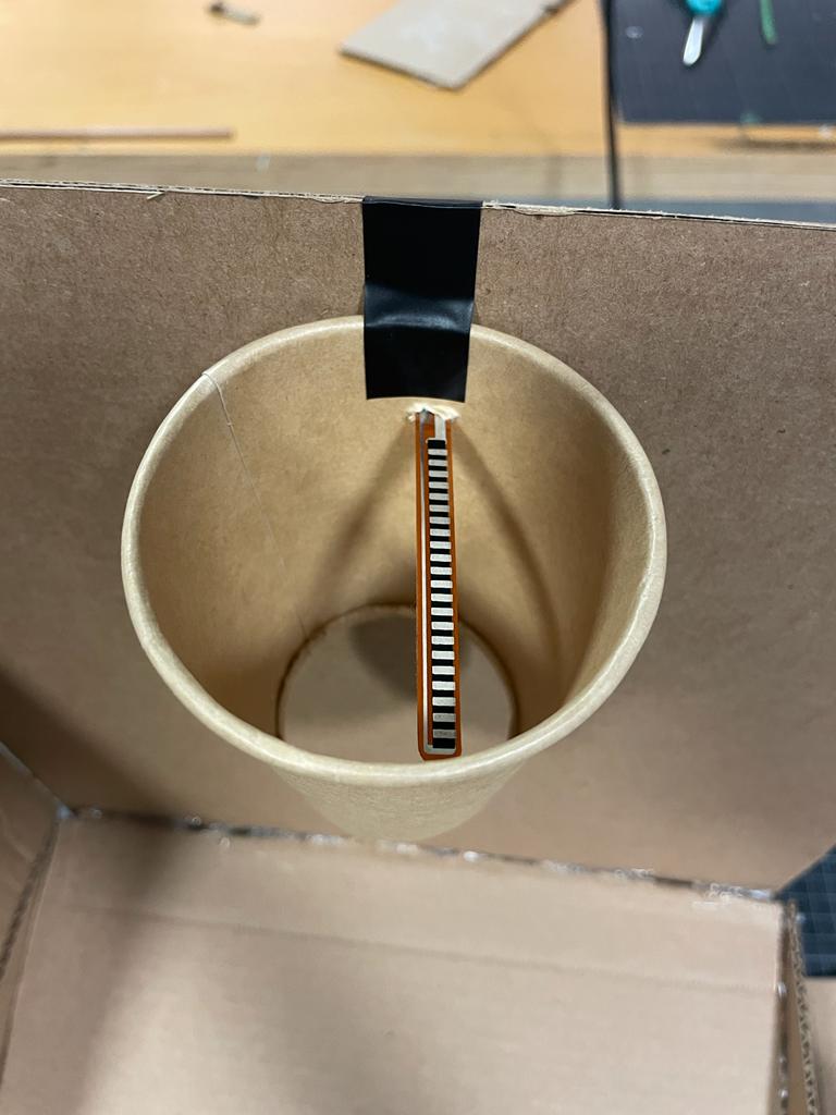
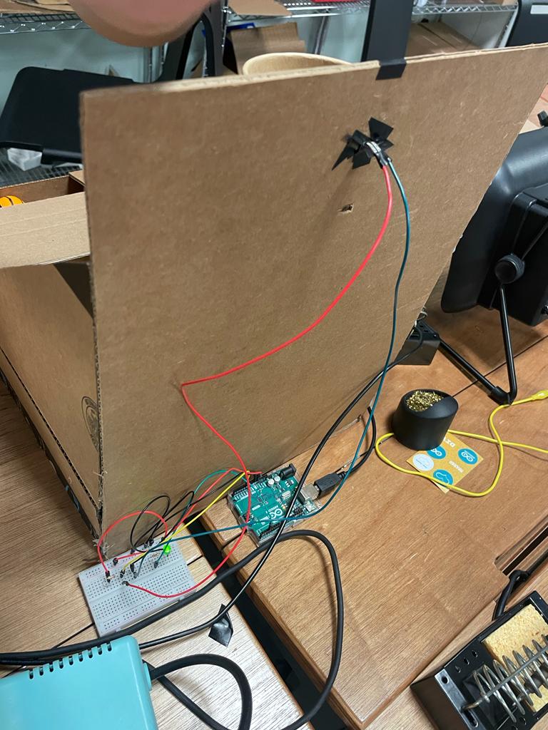
The Arduino program will read the sensor input to determine when the ball has been shot and passed through the hoop. The circuit will consist of a flex sensor and a resistor, with the flex sensor connected to an analog input on the Arduino board. The Arduino program will read the analog input to determine the current value of the flex sensor, which will change whenever a basketball passes through the hoop and contacts the sensor.
This Arduino code is designed to read analog input from a flex sensor connected to pin A0. In this case I built a sample circuit with LED to monitor if the flex sensor is working properly. The code begins by declaring constants for the LED pin (3) and the flex sensor pin (A0), and a variable to store the analog input value. In the setup function, the LED pin is set as an output pin, and serial communication is initialized at a baud rate of 9600.
The loop function continuously reads the analog value from the flex sensor using analogRead(), and then prints this value to the serial monitor using Serial.println(). The analog value is then mapped from the range 700-900 to the range 0-255 using the map() function. The resulting value is then used to control the brightness of the LED using analogWrite(), which sends a PWM signal to the LED pin. Finally, there is a small delay of 100ms before the loop starts again.
//Constants:
const int ledPin = 3;   //pin 3 has PWM funtion
const int flexPin = A0; //pin A0 to read analog input
//Variables:
int value; //save analog value
void setup(){

  pinMode(ledPin, OUTPUT);  //Set pin 3 as 'output'
  Serial.begin(9600);       //Begin serial communication
  while(Serial.available() <= 0) {
     Serial.println("0,0");
    }
}
void loop(){

  value = analogRead(flexPin);         //Read and save analog value
  Serial.println(value);               //Print value
  value = map(value, 700, 900, 0, 255);//Map value 0-1023 to 0-255 (PWM)
  analogWrite(ledPin, value);          //Send PWM value to led
  delay(100);                          //Small delay

}
Additionally, I tested photoresistor and infrared distance measurer as potential types of sensors for detecting when the basketball passes through the hoop. Based on my testing I determined that flex sensor is the most accurate and well-designed option.
COMMUNICATION BETWEEN ARDUINO/ P5.JS
The communication between Arduino and P5.js in the Mini Basketball Arcade Game is crucial for the game to function properly. The Arduino program reads the analog input from the flex sensor, which detects when the basketball passes through the hoop. Once the flex sensor value changes, the Arduino program sends this data to the P5.js program for processing and display on the scoreboard.
In order to establish communication between the two programs, the Arduino program uses the Serial communication protocol to send the sensor data to the P5.js program. The data is transmitted as a series of bytes that represent the flex sensor value. The P5.js program receives this data using the Serial communication library, which provides a way for the P5.js program to listen to the serial port and read the incoming data.
Once the P5.js program receives the flex sensor data from the Arduino program, it uses this data to update the score on the scoreboard. When data is received, the P5.js program reads the data and stores it in a variable. The P5.js program then uses this variable to update the player’s score based on the successful shots made by the player. The P5.js program also keeps track of the time remaining in the game and displays this information on the scoreboard.
What are some aspects of the project that you’re particularly proud of?
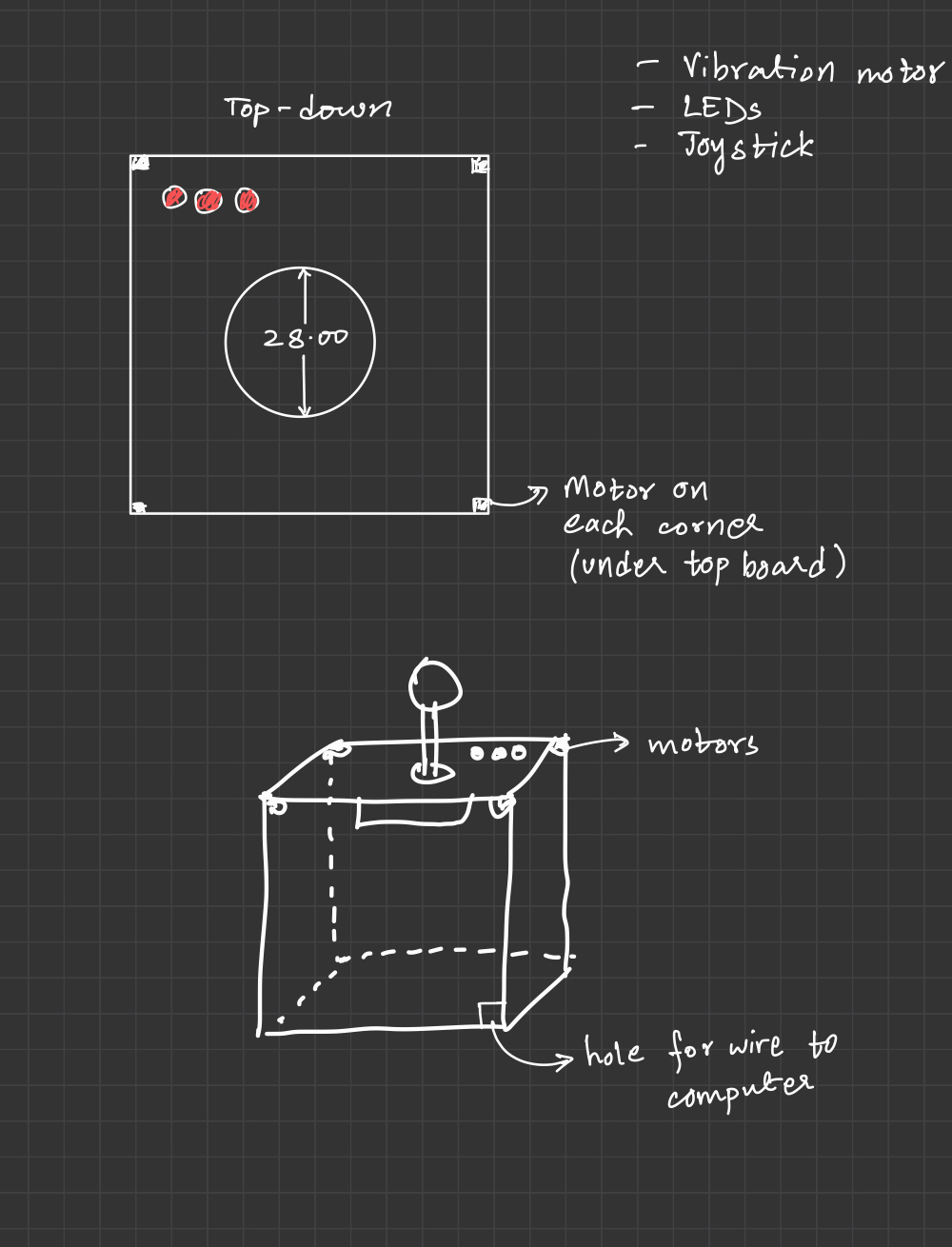
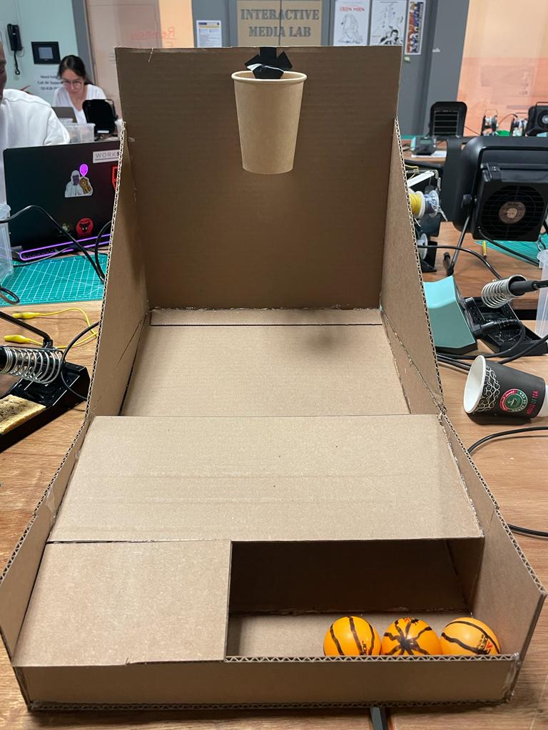
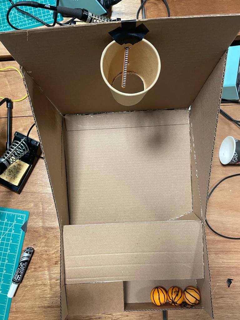
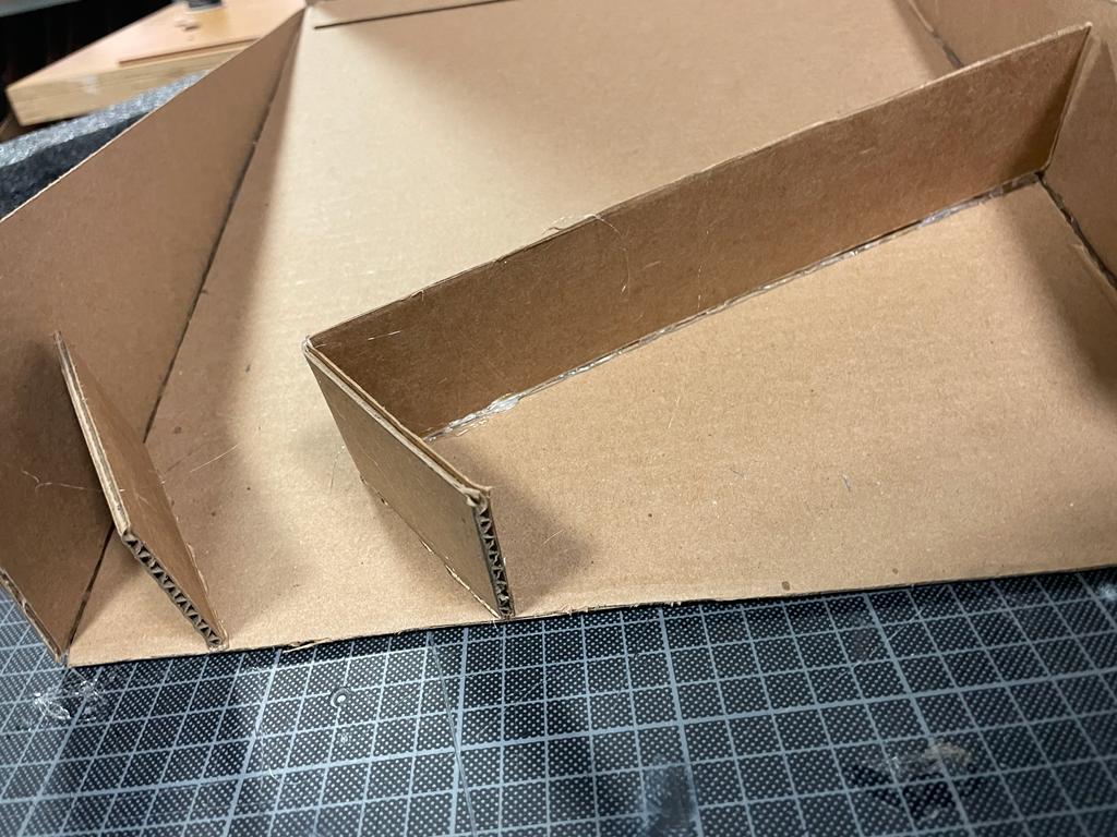
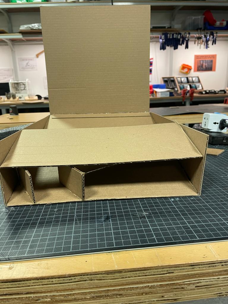
The main aspect I am very proud of in this project is the Mini Basketball Arcade Gaming Box that I created. I did not expect it to take so much time to build and design a game box, but I still enjoyed the process and came up with really user-friendly solution. I constructed a rectangular frame to support the basketball hoop, which also featured a ramp for the ball to return to the user, making it more convenient for the users to collect the balls after shooting. Following the initial user testing, I decided to enlarge the size of the frame, allowing more space for missed shots to fall onto the ramp and roll back to the user.
As you can observe from pictures above, I specifically created a path for the basketball to slide because in the first cases of user-testing I received a feedback about balls being stuck in the frame so I designed a path and additional section where used balls are stored.
To create the hoop, I repurposed a paper coffee container, and the ball was a ping pong ball that I borrowed from the Fitness Center.
What are some areas for future improvement?
One potential area is to improve the accuracy and precision of the flex sensor readings. The flex sensor used in the project is known to be sensitive to changes in temperature, humidity, and other environmental factors. Also the right positioning of the flex sensor is crucial because it needs to be centered so that it would 100% detect the falling ball. Because I used tennis balls the attachment to the hoop also caused substantial issues resulting in faulty detections.
Another potential game level could involve increasing the difficulty of the shots required to score points. For example, the basket could be moved to different locations or the size of the basket could be decreased. To implement this, the code would need to randomly generate new positions for the basket and adjust the size of the basket accordingly. The code would also need to calculate the trajectory of the ball and determine whether it goes through the basket.
User Testing
For the final user testing, I asked Aaron and Symbat to test my game without giving them any prompts/instructions . User testing was important to identifying what to work on in my project.
Are they able to figure it out? Where do they get confused and why? Do they understand the mapping between the controls and what happens in the experience?
It was very straightforward because I made the design of the game box and even tennis balls obviously basketball themed and there was not any confusion in figuring out the interaction design. They both immediately understood how to play the game and the mapping between the controls and what happens in the experience. Physical act of shooting a miniature basketball into the hoop, which is the primary user input was well implemented and tested.
What parts of the experience are working well? What areas could be improved?
The whole interaction design part is working surprisingly well. P5.js program offers an interactive and immersive basketball game, featuring a visually appealing interface with a scoreboard showing the current score and time remaining. Users can shoot basketballs through the hoop, and the program responds with feedback sounds and updates the score. The game also includes a time limit, adding an extra layer of excitement and challenge. A buzzer sounds when the time runs out, and the user can view their final score and compare it with the highest score achieved.
As mentioned before, one potential area is to improve the accuracy and precision of the flex sensor readings because sometimes when the flex sensor is tilted from its position it might count faulty results. Additionally, because I am using very light tennis ball it compromises the best positioning of sensor by getting a bit heavier ball of same size the accuracy would be perfect.
What parts of your project did you feel the need to explain? How could you make these areas more clear to someone that is experiencing your project for the first time?
I received some questions about how the shoots are detected and what sensors I used. I could provide more information about the different types of sensors being tested (photoresistor and infrared distance measurer) and how they work. This would help the user understand the reasoning behind using a flex sensor and how it compares to other potential sensor options. I can also explain about the materials and components required to build the physical arcade machine. This would give the user a better understanding of the physical aspects of the project and how they fit together.
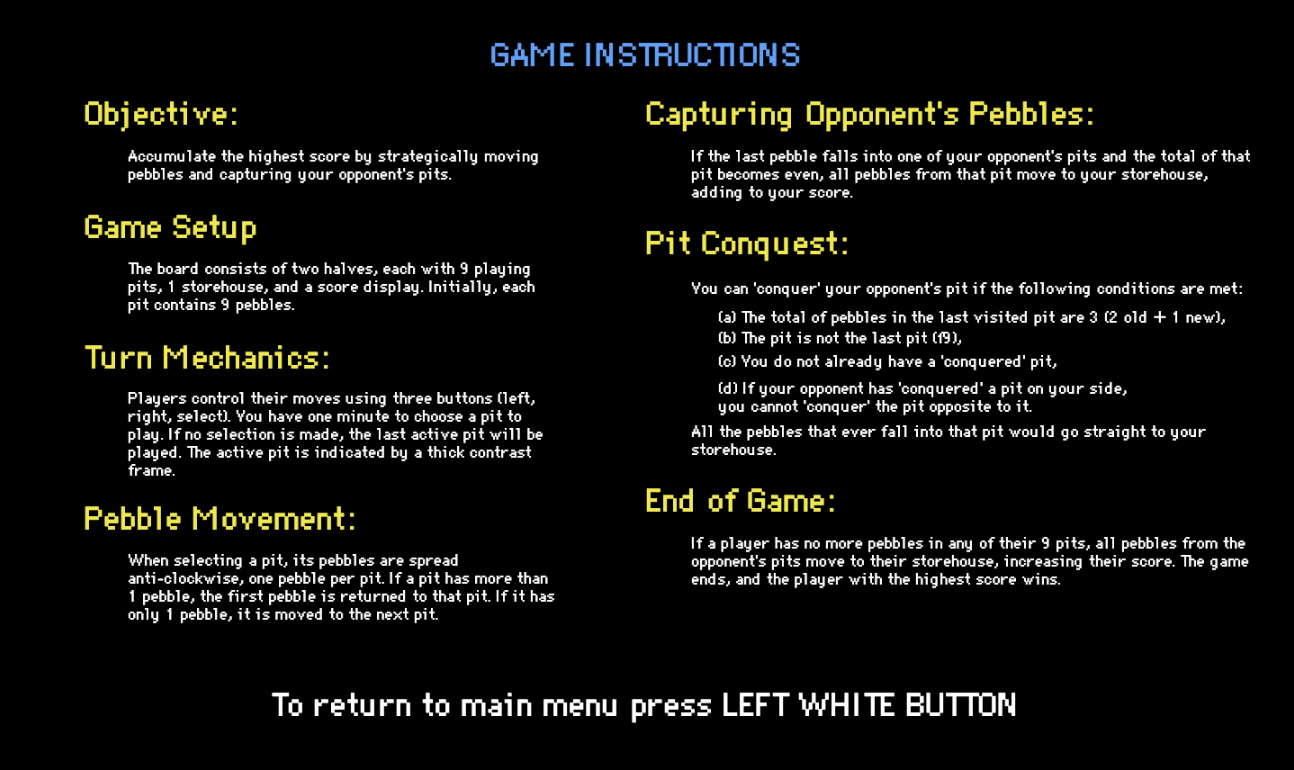
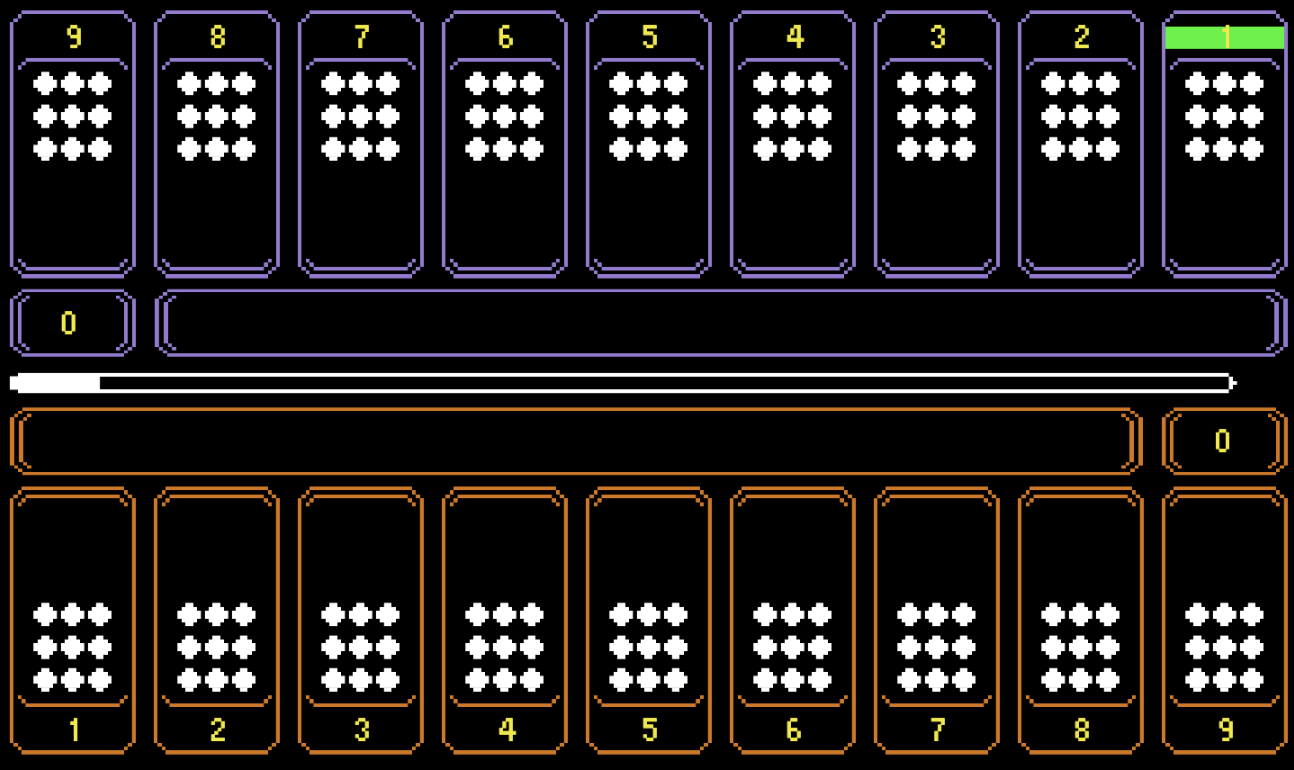
For my final project, I created a version of the Kazakh traditional two-player board game, Togyzkumalak (transl. “nine pebbles”). The game board is visualized on a p5 window, which is displayed to players through a laptop screen. The board consists of two halves, each half features 9 playing pits, 1 storehouse, and a score display.
At the beginning of the game, each pit contains 9 pebbles. Players control their moves by using a set of three buttons (left, right, enter), featured on the arcade cabinet. Each player is given a minute to choose a pit to play. If the “select” button is not pressed by the end of the timer, the last active pit will be played. The active pit is indicated by a thick contrast frame around the pit. The pebbles from the chosen pit are spread in an anti-clockwise direction, one pebble per pit. If there is more than 1 pebble in the pit, the first pebble is put back into the pit it was taken from. If there is only 1 pebble in the pit, the first pebble is moved to the next pit. If the last pebble to be moved is put into one of the opponent’s pits and the total of the pebbles in that pit is an even number, all of the pebbles from that pit get moved to the player’s storehouse and add to their total score.
The opponent’s pit can be “conquered”, meaning that all the pebbles that ever fall on that pit will move to the player’s storehouse. However, there are some more conditions that need to be followed to do that (checked by p5 automatically):
the total of the pebbles in the last pit you’ve visited must be 3 (2 old +1 new);
the pit shouldn’t be the last pit of the player (pit #9);
you must not already have a “conquered” pit;
if your opponent already has “conquered” a pit on your side, you can’t “conquer” a pit that is opposite to it;
If one of the players doesn’t have any more pebbles in any of their 9 pits, the opponent’s pits are emptied into their storehouse, incrementing their score. The game ends and the player with the highest score wins.
IMPLEMENTATION
INTERACTION DESIGN
The game is hosted on a 30*40 acrylic arcade cabinet, which features two sets of game control buttons, a menu button, and an instructions button. For the screen, I am using a 13-inch laptop, the keyboard part of which is hidden in the cabinet, so that only the screen can be seen and accessed by the players. Along with the lower part of the laptop, the Arduino setup is also neatly organized inside the cabinet. To fit both without the size of the cabinet, I have put a small box inside the cabinet. The box plays two roles, it is both a home for the Arduino kit and a pedestal for the laptop. I have used a laser cutter, duct tape, bolts, and acrylic glue to assemble the cabinet. Below the cabinet, there is a box the pure function of which is to lift up the cabinet and make the whole setup look less disproportionate.
The biggest challenge at this stage was cutting the elements individually. The laser cutting machine died in the process multiple times, which made the process very time-consuming.
ARDUINO CODE
Setting up the Arduino code was pretty intuitive. It is fully based on the example provided by the professor in class. The code consists of the declaration of 8 buttons and their states. The state of each button is read and sent to p5. An empty line is sent from p5.js to Arduino.
To view the code scroll to the end of the sketch.js file in p5. Click here to view the p5 code.
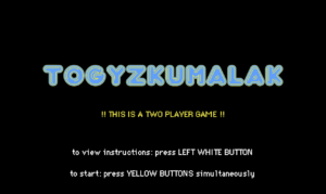
P5.JS CODE
Most time was spent on setting up p5 canvas. There are four game states (start, playing, end, and instructions) that constitute the window displayed. The title page features a blinking text to serve as a sort of warning that the game requires two players. I found it necessary to add this warning and make it visible because my midterm project was also a two-player game and despite stating in class that it is multiplayer, my fellow classmates would still attempt to play it individually, which really breaks the experience. I decided to feature instructions on a separate page because (a) I didn’t find a way to make them concise enough to feature on the title page, and (b) I believe that there will be some people who know the instructions of the game. For the end screen, I have adopted the confetti display to make it feel less empty and more festive.
The arcade style of the game was dictated by the arcade cabinet and my general liking of this style. I find the arcade art style to be fitting for whatever game idea. It is easy to implement, not too difficult to modify if needed, and makes the game look more put together.
To explain the code in a more organized way, I will be focusing on each of the major functions of the game.
Turn mechanics
The turn mechanics in the game involve managing the timer, checking if a selected pit is empty, and handling situations where a selection is not made within the allotted time.
The game utilizes the frameCount variable to keep track of the elapsed time. The timeStart variable is set to the current frameCount value at the start of a player’s turn. The timer bar is displayed, indicating the remaining time for the player’s turn. If the timer reaches the time set for a turn, the turn is automatically ended.
If the player does not make a selection within the allowed time (e.g., before the timer reaches the threshold), the turn is automatically ended and whatever pit their selection window was on, would be played. If the last selected pit is empty, pit index + 1 would be played. This is achieved by comparing the current frameCount value with the timeStart value and determining if the time limit has been exceeded. When the turn times out, the game proceeds to the next player’s turn.
Pebble movement
When there are multiple pebbles in a pit, the game determines the number of pebbles to be moved. If the pit has more than one pebble, the ballCount variable is set to the number of pebbles in the pit minus one. The pebbles are then moved one by one to the subsequent pits in an anti-clockwise direction. If there is only one pebble in the pit, a specific rule is applied. The ballCount variable is set to 1. If a player selects an empty pit, no pebbles are moved, and the player is forced to choose a pit that has pebbles in it.
Capturing opponent’s pebbles
After moving the pebbles to their respective pits, the game checks whether the total number of pebbles in the last pit visited on the opponent’s side is even. This is done by checking the index of the pit using modulo division (%), which checks if the remainder of the division by 2 is 0, indicating that the pit is even. If the final pit has an even amount of pebbles, the player’s score is incremented by the number of pebbles in the opponent’s pit. The player’s storehouse and the opponent’s pit are updated to reflect new values.
End of game
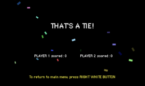
After each move, the game checks if the current player has any remaining pebbles in their pits. This is done by iterating through all nine pits of the current player and summing up the number of pebbles in each pit. If the total count of pebbles in the player’s pits is zero, it indicates that the player has no more pebbles to play with. The game state changes to “end” and the end window is displayed. The scores are compared to choose which ending message to display. An alternative way of finishing the game is by pressing the right white button.
FUTURE IMPROVEMENTS
There are a few. For a better experience of the game, it would be nice to have sound effects, music, and animations. I am an advocate for adding sound to whatever experience that doesn’t require a complete lack of sound. Especially if it’s a game. However, this time I really didn’t have the time to add by the project submission deadline. I may add it by the time of the showcase if I have some free time. As for animations, I just couldn’t figure it out. Perhaps if the distribution of the pebbles was slower and more emphasized, it would be easier to figure out the game flow for those, who didn’t understand it from instructions.
In the original game, there is also a different kind of pebble, but I don’t remember what rule is associated with it and surprisingly can’t find anything online. I do believe that it added more complexity to the game, however, it is currently difficult to explain instructions in simpler terms as it is. So for the starters, I wanted to focus on making the game’s logic and objective as understandable as possible without taking away from the strategic aspect of it.
Coming back to the display of the instructions, I feel like right now it is the biggest challenge of the game. While after user testing I was planning to have some visuals to accompany the rules, I realized that it would be more effective to explain the game in as many details as required to make the game make sense. In case players at any point want to clarify something about the rules, they can always press the button allocated specifically for this purpose. The game timer pauses for the duration of the instructions display so that players wouldn’t feel in a hurry and could actually focus on understanding the game.
One other thing is that even though it is written that to start the game players must press the yellow buttons simultaneously, most lack the group coordination to do so. I implemented this rule as one way of ensuring that there are two players at the start of the game. Maybe there is some condition I could add to make it so that as long as the other player presses within some brief time window from the first player to press the yellow button on the title screen, the game could be started.
For the user testing, I have asked a person outside of this class to test what I have so far. This includes the p5 screen only, as I was yet to have the physical part of the game and didn’t yet connect the Arduino to p5. On the p5 screen, there is an interactive board with pebbles distribution animation. The information about the order of turns, scores, and presence of any conquered pits is logged to the console and not yet displayed on the board. The turns are not timed yet.
The user was not given any instructions besides the p5 screen, so they navigated the game on their own. They have focused on using mouse clicks mainly, which correlates to the type of control that I had for p5 so far (players’ turns are played through mouse clicks on pits correlating to their side of the board). This observation indicates that it is only intuitive to want to interact with pits. I believe that the control will be even more intuitive when the physical aspect of the game will be built.
It could have been more effective if I asked two people to test the game instead of one because it is a two-player game. However, it could be observed that the user got a sense of it from the clear visual division of the board and the text from the console logs.
The tester was confused about the rules and the goal of the game. I believe that with well-written instructions, it would be an easy fix. My concern, however, is that people don’t like to read, especially when it comes to instructions. So if I make the instructions more than a few dozen of words long, people may skip through them, be confused through the game, and come to a conclusion that they don’t like it, when it’s actually very fun (like me with chess). I will try to add images where appropriate, however, I am not sure if images alone will suffice.
The video of the user testing is attached below. If the video window doesn’t show, use this link to view it.
For user testing, we asked Aaron to test our game without giving him any prompts/instructions (thank you, Aaron!). User testing was important to highlight 2 major issues with the project at the moment:
We did not make instructions super clear and eye-catching. Aaron skipped through reading them.
The complexity of the game levels was a bit too much. It was challenging to complete some of them and car movements made it sometimes impossible.
The interesting part of our project involves not so standard way of controlling the movement across screens in p5js. We use a physical wooden piece – controller labelled C. User testing showed that players can get confused and use arrows instead and then use hands, instead of the controller, to move.
After some explanation on the controller part, the experiences with navigating through levels were working well. Some areas of improvement included reducing the complexity. At some levels, the door was not wide enough to be easily passed, or cars made the player die too often and it got annoying quickly.
Post-user testing edits on the project included:
We added more instructions. We have even changed the text colour to include some contrast. The image of the physical component – the board and controller – was included in the p5js entry screen as well.
The complexity of game levels was reduced to make the game experience more enjoyable while intentionally leaving this feeling of being a bit frustrated.
For the final project, I decided to create an experience which involves interactivity through buttons, led lights, a fan and a screen. During finals week we have so much to work on that we neglect nature and its healing powers, so I decided to bring that indoors and onto our screens as a way to create an enjoyable and relaxing experience.
This project consists of the screen display part which is coded on P5, and the user interactivity with buttons, a potentiometer, a fan and the neopixel ring lights. Here is a demo to show the experience better:
Interaction
One can switch through the different elements to experience them: rain, fire, or earth&wind. For a more immersive feel beyond the simulations on the screen, I decided to have light shows on a neopixel ring with patterns which imitate what is happening on the screen. The magnitude of the potentiometer affects what is happening in the simulations.
Higher magnitude in rain leads to more raindrops and at higher speeds. In the lightshow this translates to the raindrops rotating faster. The fan is activated during rain, as wind is often associated with rain.
Higher magnitude in fire leads to more fire particles and a bigger spread (essentially more fire). In the lightshow this is shown by how high the fire reaches the top of the ring. The fan is off at this time.
Magnitude in earth&wind affects the direction of the wind on the screen. The light show is unrelated to the work of the potentiometer, as the light show is imitating the piling of the leaves on the screen, which happens at a constant rate regardless of the values of the potentiometer. It is interesting to note that the constant rate of the leaf piling creates an hourglass effect on both the screen and the neopixel ring (the pile gets higher after a constant x amount of time). The fan is turned on to imitate the wind.
Arduino
The arduino works by taking as input the values of the switches and the potentiometers, and outputting the neopixel light show patterns as well as turning the fan on and off when appropriate.
The Fan
The fan required a higher voltage than the 5V that arduino supplies, so in order to get it to work I had to use a different power source and use a transistor in order to control the fan through the arduino. As for code, I simply had to do a digitalWrite of HIGH on the appropriate pin when I wanted it on and digitalWrite of LOW when I wanted it off.
Light Shows
I had to come up with my own patterns for the light shows to imitate best what I had come up with for the screen. Because of the ring shape of the neopixel, I had to get very creative, since the screen is a rectangle.
For the raindrops, I decided to create 4 raindrops which go around in a clockwise direction, and the magnitude of the rain would affect the speed at which they go around. To create a more interesting effect, I created the raindrops as a sort of trail, where the pixel at the front was the brightest, and the 2 pixels behind it each get dimmer, followed by fully dim pixels to distinguish between the rain drops. Here is the code for this pattern:
void raindrops(int del) {
  //map potentiometer value to del
  del = map(del, 40, 1020, 150, 30);
  // a total of 24 pixels
  // separate into 4 sections by tackling 6 pixels at a time
  for(int i=0; i<6; i++) {
    //first pixels in the section are dark
    pixels.setPixelColor(i, pixels.Color(0, 0, 0));
    pixels.setPixelColor(i+6, pixels.Color(0, 0, 0));
    pixels.setPixelColor(i+12, pixels.Color(0, 0, 0));
    pixels.setPixelColor(i+18, pixels.Color(0, 0, 0));

    //second pixels in the section are dark
    pixels.setPixelColor(i+1, pixels.Color(0, 0, 0));
    pixels.setPixelColor(i+7, pixels.Color(0, 0, 0));
    pixels.setPixelColor(i+13, pixels.Color(0, 0, 0));
    pixels.setPixelColor(i+19, pixels.Color(0, 0, 0));

    //third pixels in the section are dark
    pixels.setPixelColor(i+2, pixels.Color(0, 0, 0));
    pixels.setPixelColor(i+8, pixels.Color(0, 0, 0));
    pixels.setPixelColor(i+14, pixels.Color(0, 0, 0));
    pixels.setPixelColor(i+20, pixels.Color(0, 0, 0));

    //fourth pixels in the section are dim
    pixels.setPixelColor(i+3, pixels.Color(20, 20, 20));
    pixels.setPixelColor(i+9, pixels.Color(20, 20, 20));
    pixels.setPixelColor(i+15, pixels.Color(20, 20, 20));
    pixels.setPixelColor(i+21, pixels.Color(20, 20, 20));

    //fifth pixels in the section are brighter
    pixels.setPixelColor((i+4)%NUMPIXELS, pixels.Color(100,100,100));
    pixels.setPixelColor((i+10)%NUMPIXELS, pixels.Color(100,100,100));
    pixels.setPixelColor((i+16)%NUMPIXELS, pixels.Color(100,100,100));
    pixels.setPixelColor((i+22)%NUMPIXELS, pixels.Color(100,100,100));

    //sixth pixels (at the front) in the section are the brightest
    pixels.setPixelColor((i+5)%NUMPIXELS, pixels.Color(200, 200, 200));
    pixels.setPixelColor((i+11)%NUMPIXELS, pixels.Color(200, 200, 200));
    pixels.setPixelColor((i+17)%NUMPIXELS, pixels.Color(200, 200, 200));
    pixels.setPixelColor((i+23)%NUMPIXELS, pixels.Color(200, 200, 200));

    pixels.show();   // Send the updated pixel colors to the hardware.

    delay(del); //delay affects how fast the raindrops are moving
  }
}
For the fire, I decided to have the fire start at the bottom of the ring, and get reach higher the higher the value of the potentiometer. To create a realistic fire crackling effect, I had to experiment a lot with colors and dimness, the colors at the bottom had to be more yellow and brighter, and the colors at the top had to be more red and dimmer – and this all had to be relative to the total height of the fire. To achieve this, I had to do a lot of calculations and a lot of experimenting until I got it right. Here is the code which gave me the desired effect:
void fire(int maxNum){ //maxNum should be 4 to 12
  //maxNum refers to the height of the fire. the number corresponds
  //to how many pixels will be colored on each side.
  maxNum = map(maxNum, 40, 1024, 4, 12);

  //changing delay so that the fire crackles and changes more
  //the larger the fire is
  DELAYVAL = map(maxNum, 4, 12, 50, 25);

  for(int i=0; i<maxNum; i++) {
    //calculating the dimness in relation to how many pixels there are
    //in total
    double percentage=1-0.1*map(i, 0, maxNum, 0, 10);

    //do not dim the first maxNum/3 pixels
    //the fire at the bottom must be brightest
    if(i>maxNum/3){
      // pixels.setPixelColor(i, pixels.Color(int(random(100,255)*0.1*(maxNum-i)), int(random(40)*0.1*(maxNum-i)), 0));
      // pixels.setPixelColor(NUMPIXELS-i, pixels.Color(int(random(100,255)*0.1*(maxNum-i)), int(random(40)*0.1*(maxNum-i)), 0));
      pixels.setPixelColor(i, pixels.Color(int(random(100,255)*percentage), int(random(40)*percentage), 0));
      pixels.setPixelColor(NUMPIXELS-i, pixels.Color(int(random(100,255)*percentage), int(random(40)*percentage), 0));
    }
    else{
      //full brightness
      pixels.setPixelColor(i, pixels.Color(random(150,255), random(10,60), 0));
      pixels.setPixelColor(NUMPIXELS-i, pixels.Color(random(150,255), random(10,60), 0));
    }

    pixels.show();   // Send the updated pixel colors to the hardware.

    delay(DELAYVAL); // Pause before next pass through loop

  }
  //turn off the pixels above the current height, if the height decreases
  for(int i=maxNum; i<13; i++) {
    pixels.setPixelColor(i, pixels.Color(0,0,0));
    pixels.setPixelColor(NUMPIXELS-i, pixels.Color(0,0,0));
  }
}
For the leaves, I wanted to imitate the pile of leaves which is being accumulated on the screen. So I get the level of pile that has been reached from P5, and light up a corresponding number of pixels. I use alternating shades of pink to imitate the colors of the leaves on the screen, which are also alternating. Here is the code:
void leaves(int leavesNum) {
  for(int i=0; i<leavesNum; i++) {
    //turn on fan
    digitalWrite(fan, HIGH);

    //light up two pixels at a time on each side
    //left side
    pixels.setPixelColor(2*i, pixels.Color(255, 0, 144));
    pixels.setPixelColor(2*i+1, pixels.Color(255, 69, 174));

    //right side
    pixels.setPixelColor(NUMPIXELS-2*i, pixels.Color(255, 0, 144));
    pixels.setPixelColor(NUMPIXELS-2*i+1, pixels.Color(255, 69, 174));

    pixels.show();
    delay(1);
  }
}
Beyond that in arduino, I receive values from the buttons to determine which simulation to experience, and display the appropriate light show, and turn on and off the fan whenever needed. I will discuss the arduino/P5 connection below.
P5
For the simulations, I utilized objects and arrays to create them. If you notice, each of the simulations is made up of small similar particles which are created and disappear in different ways. We have raindrops, fire particles and leaves. The code for each of the classes is quite similar, with small differences to create the different simulations, as the particles look and behave differently for each of the simulations, but they follow a similar structure. Here is the code for one of them:
class RainDrop {
  constructor() {
    //randomly decide horizontal location
    this.x = random(0, width);
    //start at the top of the screen
    this.y = 0;
    //random vertical speed
    this.vy = random(5,8);
    //random vertical diameter
    this.d = random(5,8);
    //color variation, create different shades
    //of light blue
    this.R = random(190,200);
    this.G = random(190, 200);
    this.B = random(200,255);
  }

  //finished when they reach the bottom of the screen
  finished() {
    return this.y > 600;
  }

  //update postition based on vertical speed
  update() {
    //add additional boost based on the value of the
    //potentiometer to increase vertical speed
    this.y += this.vy + map(potVal, 100, 1020, 0, 3);
  }

  //drawing out the particle
  show() {
    noStroke();
    fill(this.R, this.G, this.B);
    ellipse(this.x, this.y, 5, this.d);
  }
}
And here is how the objects are created, updated and deleted:
function create_rain() {
  //redraw rain background
  image(rain_bg, 0, 0, 600, 400);

  //max num of raindrops created at a time
  //determined by the potentiometer
  let maxI = map(potVal, 40, 1020, 2, 10);

  if(frameCount%5==0){
    for (let i = 0; i < maxI; i++) {
      let p = new RainDrop();
      rain_drops.push(p);
    }
  }
  //update raindrops, and delete them when they are finished
  for (let i = rain_drops.length - 1; i >= 0; i--) {
    rain_drops[i].update();
    rain_drops[i].show();
    if (rain_drops[i].finished()) {
      rain_drops.splice(i, 1);
    }
  }
}
Since the code for the other simulations follows a similar structure, I will not attach it so as not to be repetitive.
P5/Arduino Communication
At first a handshake is established to ensure communication exists before proceeding with the program:
//arduino code

while (Serial.available() <= 0) {
    Serial.println("-1"); // send a starting message
    delay(300);            // wait 1/3 second
  }
Then, the arduino constantly sends the values of the potentiometer and the values of which button was pressed last. It reads from P5 the value of the leaf pile, which it uses later for the light show:
int leavesNum = Serial.parseInt();
if (Serial.read() == '\n') {
   Serial.print(potPosition);
   Serial.print(",");
   Serial.println(currentButton);
}
Here is how P5 reads these values and also sends the leaf pile value:
// This function will be called by the web-serial library
// with each new *line* of data. The serial library reads
// the data until the newline and then gives it to us through
// this callback function
function readSerial(data) {
  ////////////////////////////////////
  //READ FROM ARDUINO HERE
  ////////////////////////////////////

  if (data != null) {
    // make sure there is actually a message
    // split the message
    let fromArduino = split(trim(data), ",");
    // if the right length, then proceed
    if (fromArduino.length == 2) {
      // store values
      //potentiometer value
      potVal = fromArduino[0];
      currentButton = fromArduino[1];
    }

    //////////////////////////////////
    //SEND TO ARDUINO HERE
    //////////////////////////////////
    let sendToArduino = leaf_bg_choice+1 + "\n";
    writeSerial(sendToArduino);
  }
}
Strengths
As a computer science student, I am comfortable with programming. For this project I wanted to challenge myself creatively. From the creativity of the idea itself, to the screen simulations, light shows and even the crafty parts of assembling the interactive box – I pushed myself creatively as much as I could. This was an incredible learning experience for me. I learned that I can be quite resourceful even with hand work such as creating the box out of cardboard and paper, creating a cardboard ring and pinning down cloth to create a ‘lampshade’ for the neopixel. I also had so many connections and circuits, and that lead to many challenges, but it also taught me so much.
As for the user experience, I think it serves its purpose quite well – it is very simple in its usage, that the testers which you will see below required no instruction before or after to learn how to use it. And it is quite a relaxing experience, you just get to play around and enjoy the different elements, and enjoy my creative efforts at visual arts – whether it is the screen simulations or the light shows. The testers particularly enjoyed the light shows, and were very pleasantly surprised by the fan.
Weaknesses
While working on this project I ran into problem after problem. Starting with the problems I anticipated well in advance, such as learning how to use a neopixel, learning how to connect a fan and learning how to solder. These took only a matter of seeking out help from my professor and/or the internet depending on the task – so they were easier challenges to overcome, I just needed to educate myself on how to do them.
The unexpected problems were quite tough. Since I am dealing with arrays of objects in my code, I had to work on optimizing the code so I do not overwork the computer and have it result to low fps. I already had plenty of experience with that in my midterm project, so this was a relatively easy fix too.
My biggest problem was with the potentiometer. Unfortunately, I am still unsure that I solved the issue at the root – but I learned how to avoid the problem. As long as I arrange my circuits evenly, and keep the wires neat and straight, the potentiometer will give me values that are stable enough for my purposes. But the problem is that the values are not entirely stable. For my purposes though, the problem is somewhat solved – at least enough for my project to work fine.
I believe a lot of the problem from above came from using a breadboard, if I used soldering instead I would have a more stable connection and thus more stable values. In a case where this was a more permanent installation, I would most definitely have to switch out of the breadboard – but this works currently.
User testing
I had two people come and test the project with no instructions beforehand. Both of them had no problems figuring out exactly how the experience works and being able to play around with it exactly as intended. They understood exactly what the buttons and the potentiometer did and would check the screen and the neopixel for the results of their work with the potentiometer.
The simplicity of the interactions worked very well, and both testers reported to have had an enjoyable and relaxing experience.
One area of improvement is with the buttons. The buttons themselves are not very sensitive, and the cardboard box is soft, so the user has to push hard to change the simulation. I put support right underneath the buttons to combat this, but it still wasn’t enough to entirely eliminate the inconvenience. However, the user does not need to push too hard, so it is easy to get used to pushing it the right amount – for my own tests I experienced no problems, but people using it for the first time faced a few challenges.
To fix the responsiveness of the buttons, I would switch out the cardboard box for something stiffer and stronger, like acrylic or wood.
Akyn is a Jarvis(Iron Man) like artificial intelligence that helps to make morning and night routines more pleasant. As a student, I can indeed say that many of us are lazy. We keep procrastinating a lot and as a result, get stressed out when the deadline approaches. Akyn is a way to change that. With only 2 buttons, you can escalate your morning and night routines to a new level.
As part of the morning routine, Akyn will turn on the AC for you and greet you in a respectful manner. Afterward, it will read out(over voice) the emails you have gotten over the night. And as a last action, it will play motivational music so there is no way you still lay in your bed.
When you go to sleep, Akyn will turn off the lights and AC for you. Afterward, Akyn voices over your alarm time for tomorrow and starts listing the events from your Google Calendar for tomorrow. This way you will start visualizing tomorrow starting from tonight.
How does the implementation work?
Description of interaction design
The interaction design is very simple. There are 2 buttons on the breadboard located right near your bed. Green button for morning routine and Blue button for night routine. By pressing one of them, the respectful routine gets triggered.
Description of Arduino code
The Arduino concept is very simple. There are 2 buttons and 2 servo motors connected. In the setup, I connect the motors and start the handshake process with the p5.js. In the main loop, while there is a connection established, I keep waiting for the user to press either of the buttons. Once one of them is pressed the motor(s) start rotating which turns on/off AC/lights. Lastly, 0 or 1 is sent to the p5.js indicating which button is pressed.
#include <Servo.h>

Servo servo_lights_off;
Servo servo_AC;

int pin_GM_button = 2;
int pin_GN_button = 4;

int pin_lights_off = 11;
int pin_AC = 9;

int state_GM_button = 0;
int state_GN_button = 0;
int prev_state_GM_button = 0;
int prev_state_GN_button = 0;

void setup() {
  servo_lights_off.attach(pin_lights_off);
  servo_AC.attach(pin_AC);
  Serial.begin(9600);

  // start the handshake
  while (Serial.available() <= 0) {
    Serial.println("-1"); // send a starting message
    delay(300);            // wait 1/3 second
  }
}

void loop() {
  while (Serial.available()) {
    state_GM_button = digitalRead(pin_GM_button);
    state_GN_button = digitalRead(pin_GN_button);
    // GM button is pressed
    if (state_GM_button != prev_state_GM_button && state_GM_button == 1) {
      // turn on the AC
      servo_AC.write(180);
      delay(1000);
      servo_AC.write(0);
      delay(1000);

      // send message to P5.js
      Serial.println("0");
    }
    // GN button is pressed
    if (state_GN_button != prev_state_GN_button && state_GN_button == 1) {
      // turn off the lights
      servo_lights_off.write(0);
      delay(1000);
      servo_lights_off.write(180);
      delay(1000);
      // turn off the AC, double click is needed to go to Night mode from Morning mode
      servo_AC.write(180);
      delay(1000);
      servo_AC.write(0);
      delay(2000);
      servo_AC.write(180);
      delay(1000);
      servo_AC.write(0);
      delay(2000);

      // send message to P5.js
      Serial.println("1");
    }

    // update the previous states of the buttons
    prev_state_GM_button = state_GM_button;
    prev_state_GN_button = state_GN_button;
  }
}
Description of p5.js code
P5.js is where the main magic happens. The main interaction happens in the javascript file while the authorization happens in the index.html page.
Authorization
When the user starts the code after a specific amount of time(10 seconds for the user to have some time to read the instructions) authorization script is run. This script sends requests to Google Calendar API and Gmail API over the gapi library. As a result, I am now able to send get requests to the Google API. After the authorization, I load the calendar using a specific query indicating what kind of events I want to see. All of this is saved into the CALENDAR_EVENTS variable
<script>

    const gapiLoadPromise = new Promise((resolve, reject) => {
      gapiLoadOkay = resolve;
      gapiLoadFail = reject;
    });
    const gisLoadPromise = new Promise((resolve, reject) => {
      gisLoadOkay = resolve;
      gisLoadFail = reject;
    });

    var tokenClient;

    (async () => {
      // First, load and initialize the gapi.client
      await gapiLoadPromise;
      await new Promise((resolve, reject) => {
        // NOTE: the 'auth2' module is no longer loaded.
        gapi.load('client', {callback: resolve, onerror: reject});
      });
      await gapi.client.init({
        // NOTE: OAuth2 'scope' and 'client_id' parameters have moved to initTokenClient().
      })
      .then(function() {  // Load the Google API's discovery document.
        gapi.client.load('https://www.googleapis.com/discovery/v1/apis/calendar/v3/rest');
        gapi.client.load('https://www.googleapis.com/discovery/v1/apis/gmail/v1/rest');
      });

      // Now load the GIS client
      await gisLoadPromise;
      await new Promise((resolve, reject) => {
        try {
          tokenClient = google.accounts.oauth2.initTokenClient({
              client_id: google_calendar_USER_ID,
              scope: 'https://www.googleapis.com/auth/calendar.readonly https://www.googleapis.com/auth/gmail.readonly',
              prompt: 'consent',
              callback: '',  // defined at request time in await/promise scope.
          });
          resolve();
        } catch (err) {
          reject(err);
        }
      });
    })();

    // get token in case error while authorizing appeared
    async function getToken(err) {

      if (err.result.error.code == 401 || (err.result.error.code == 403) &&
          (err.result.error.status == "PERMISSION_DENIED")) {

        // The access token is missing, invalid, or expired, prompt for user consent to obtain one.
        await new Promise((resolve, reject) => {
          try {
            // Settle this promise in the response callback for requestAccessToken()
            tokenClient.callback = (resp) => {
              if (resp.error !== undefined) {
                reject(resp);
              }
              // GIS has automatically updated gapi.client with the newly issued access token.
              resolve(resp);
            };
            tokenClient.requestAccessToken();
          } catch (err) {
            console.log(err)
          }
        });
      } else {
        // Errors unrelated to authorization: server errors, exceeding quota, bad requests, and so on.
        throw new Error(err);
      }
    }

    function loadCalendar() {
      const tomorrow = new Date();
      tomorrow.setDate(tomorrow.getDate() + 1);
      tomorrow.setHours(0, 0, 0, 0);

      const after_tomorrow = new Date();
      after_tomorrow.setDate(after_tomorrow.getDate() + 2);
      after_tomorrow.setHours(0, 0, 0, 0);

      var calendar_query = { 'calendarId': 'primary', 'timeMin': tomorrow.toISOString(), 'timeMax' : after_tomorrow.toISOString(), 'singleEvents': true, 'orderBy': 'startTime'};

      // Try to fetch a list of Calendar events. If a valid access token is needed,
      // prompt to obtain one and then retry the original request.
      gapi.client.calendar.events.list(calendar_query)
      .then(calendarAPIResponse => CALENDAR_EVENTS = JSON.stringify(calendarAPIResponse))
      .catch(err  => getToken(err))  // for authorization errors obtain an access token
      .then(retry => gapi.client.calendar.events.list(calendar_query))
      .then(calendarAPIResponse => CALENDAR_EVENTS = JSON.stringify(calendarAPIResponse))
      .catch(err  => console.log(err));   // cancelled by user, timeout, etc.
    }

    // call loadCalendar after 3 seconds so that gapi.client initiates connection
    setTimeout(loadCalendar, 10000);

  </script>
Main logic
Now once everything is loaded, the client connects the Arduino and p5.js by simply clicking on the screen and selecting the Arduino port. From now on, everything gets triggered once the button is pressed.
Green button – goodMorning function gets called.
1) Load Gmail information about unread emails
2) Clear up the saved array, leaving only the necessary information to display
3) P5.speech libraries voices over the amount emails received, the subject, and the sender info of each one as well. Upon completion, Mozart’s Eine kleine Nachtmusik classical music starts playing.
/* voices over the Good Morning mode*/
function goodMorning() {
  // load the unread emails
  loadGmail();

  // timeout to wait till the above functions finishes execution
  setTimeout(function() {
    clearEmails();
  }, 2000);

  setTimeout(function() {
    myVoice.speak(GM_PHRASES[Math.floor(Math.random()*GM_PHRASES.length)] + "You've got " + emails.length + " emails while you were sleeping.");
    if (emails.length === 0) {
      return;
    }
    emails.forEach((email, index) => {
      setTimeout(function() {
        console.log(numberMapping[index + 1] + ' email is from ' + email.from + ' about ' + email.subject); // -> debug
        myVoice.speak(numberMapping[index + 1] + ' email is from ' + email.from + ' about ' + email.subject);
      }, (index + 1) * 10000); // wait for the previous voice to finish before starting next one
    });
    setTimeout(function() {
      myVoice.speak("Turning on music!");
    }, (emails.length + 1) * 10000);
    setTimeout(function() {
      playMusic();
    }, (emails.length + 1) * 10000 + 3000); // wait till events finishes voicing and the previous line too.
  }, 6000); // this timer is the sum of the before called timers (1000 + 3000) + 1000 extra miliseconds
}
Blue button – goodNight function gets called.
1) Clear up the saved calendar events, leaving only necessary information to display
2) Voice over the number of events and the time the alarm is set to.
3) Voice over each of the events, time, and location
/* voices over the events happening tomorrow*/
function goodNight() {
  events = clearEvents();
  setTimeout(function() {
    const eventsLength = events.length - 1;
    let p = "Tomorrow you have " + eventsLength + " events. Your alarm is set to " + events[0]['startTime']+ " AM. " + GN_PHRASES[Math.floor(Math.random()*GN_PHRASES.length)];
    myVoice.speak(p);
    // console.log(p);
  }, 1500);

  // iterate thoruhg events and voice them over
  // timeout used since forEach does not wait for the voice to finish which gives undesired output
  for (let index = 1; index < events.length; index++) {
    const event = events[index];
    setTimeout(function() {
      console.log(numberMapping[index] + ' event is ' + event['eventName'] + ', happening from ' + event['startTime'] + ' till ' + event['endTime'] + ' at ' + event['location']);
      myVoice.speak(numberMapping[index] + ' event is ' + event['eventName'] + ', happening from ' + event['startTime'] + ' till ' + event['endTime'] + ' at ' + event['location']);
    }, index * 13000);
  }
}
Description of communication between Arduino and p5.js
Due to the nature of the project, communication is one-sided. P5.js keeps waiting for Arduino to send 0 or 1 after which the main logic happens. Arduino does not need any input from p5.js all it does is wait for the buttons to be pressed.
What are some aspects of the project that you’re particularly proud of?
I am very proud of embedding Google API’s into my project. This is something I have not done before nor was it reached in any of the classes. Yet this is something very useful and applicable in a lot of spheres. By doing this, I was able to make the project actually helpful and not just some dummy toy. I believe that the use of this API together with the speech library and servo motors makes the project very unique.
Also, coming up with balanced values for timeout is something to be proud of. All API requests need to be timeout so that the next functions can use the result of that get request. I experimented a lot with these values so that users do not wait too long and the response has enough time to arrive.
What are some areas for future improvement?
In the future, I would be happy to change the timeouts to Future Promises, so that the further functions only get triggered once the previous ones finish. This way it’s not hardcoded and works with any amount of response.
Working with wires was fun, however, it would be much more flexible and convenient to use either a Bluetooth connection or even a phone. With a little bit of research, I can substitute long and limited wires to a Bluetooth connection between the breadboard and Arduino. With more research, I will be able to write a telegram bot that sends commands directly to Arduino without any buttons.
Have people try your project without giving them any prompts/instructions and see how they use it
Are they able to figure it out? Where do they get confused and why? Do they understand the mapping between the controls and what happens in the experience?
I invited a few friends to try out my project. They really enjoyed the instructions screen and it was very straightforward to authorize Google Account. However, a useful comment I received was to specify the name of the port to which users have to press in order to establish a connection to the Arduino.
Further interaction was also very clear to my friends. They went near my bed and pressed either a blue or green button.
What parts of the experience are working well? What areas could be improved?
They enjoyed a lot the voiceover of the calendar and Gmail. They also liked my choice of music. One thing they stated can be improved is the choice of voices. Since p5 speech libraries hold more than 100 voices, people would like to pick one that they want to hear the most. I believe this is something that can be implemented, nevertheless, I did not want to complicate the project with voice pick since it does not align with the main goal of improvement of morning and night routines.
What parts of your project did you feel the need to explain? How could you make these areas clearer to someone experiencing your project for the first time?
I had to explain to them that once the button is pressed they have to wait till the whole routine is finished before pressing a button again. If someone rushes with a button press, the voice will queue up and some of them will be dropped which is highly undesirable. A possible solution for this is to lock the button action until the whole routine has finished(send value from p5.js to Arduino when everything is finished and keep waiting for a response on Arduino). This can be a great addition if I decide to improve the project in the future.
The aim of this project is to create a robot that can avoid collisions and sudden edges while moving around. The robot will be controlled using an Arduino board and p5.js, a JavaScript library for creative coding. The robot will be equipped with an ultrasonic distance sensor and an infrared sensor to detect collisions and edges respectively. The robot will have two different modes of operation which can be controlled using serial communication between the Arduino and p5.js. One mode will allow the robot to roam freely, while the other mode will allow the user to control the robot using keys on the computer. The movement of the robot will be mapped onto the p5.js canvas.
Design: Arduino to p5 and p5 to Arduino
There are two arduinos – one of them is connected to the robot car and the other one is connected to the laptop. They contact with each other wirelessly. The arduino takes in data from p5 through Serial communicationand relays it over to the arduino connected on the robot car. This data helps in driving the robot car and switching between different modes. The robot car looks out for collisions and edges and moves making sure to avoid them. The direction that the car moves for is transmitted back from one arduino to the other (connected to the computer) wirelessly and then finally relayed back to p5 using serial communication.