Assignment 1: Self Portrait

As a newbie with Java Script and P5Js, I was hesitant initially and did not know what exactly to draw. However, after watching a meme video on youtube I got the idea of creating a simple vector-like face that represented the following emotion perfectly:

Embedded code:

The art is simple but it allowed me to experiment with the placement of elements in a simple Js background and manipulating them to present different features


Reflection:

I would have liked to make the portrait more interesting by playing around with different commands such as noStroke, Fill, etc. But this experience gave me an opportunity to work with the holes in my own experience which I look forward to filling going forwards.


analog input & output

For this assignment I had to get info from at least one analog and one digital sensor using two LEDs. There were different attempts to do this, as well as various outcomes. I experimented with using some methods to connect the LEDs to the sensor as well as the LEDs to the switch button.

A few resources I have found useful:
https://www.youtube.com/watch?v=4fN1aJMH9mM
https://www.youtube.com/watch?v=0p1B74TosTs

The challenge for me was to connect the LEDs to the sensor when I pressed the button and also if I waved over the sensor, it would react on actions. I managed to do it separately for the button and the sensor.

Video:
IMG_5987

Code:


int LDR = 0;
void setup() {
pinMode(12, OUTPUT);
pinMode(13, OUTPUT);
pinMode(A0, INPUT);
Serial.begin(9600);
}
void loop() {
LDR = analogRead(A0);
Serial.println(LDR);
if(LDR < 512) { digitalWrite(12, 1); digitalWrite(13, 1); } else { digitalWrite(12, 0); digitalWrite(13, 0); } }

However, I could not connect the sensor and the button because the light sensor stopped working when I connected the button. I tried redoing my circuit completely, but it was not quite working. It seemed that the button and the light sensor worked together when I could turn the LEDs on with a movement over the sensor and turn them off with the button, but as it turned out later, this was a glitch in the program, not the final result.
In reflection of this, next time I would like to work and understand the code better, so that I could fix the issue I had in this task.

Unusual switch

Concept:

Making a switch with Arduino that lights up a LED when you step on it was an efficient and convenient solution for waking up in the morning. I chose to create this project because I wanted to make something that was easily accessible and user-friendly. The switch was designed to be placed next to the bed, so that when you wake up in the morning, all you have to do is step on it to turn on the LED and start your day.


Reflections and improvements:

Reflecting on the experience of making a switch with Arduino, I found it to be both a difficult and a fun process. Initially, it was challenging for me to come up with an idea for the project. I wanted to create something that was useful and interesting, but I struggled to come up with a specific concept. Eventually, I decided to make a switch that would light up a LED when you step on it, and I found this idea to be both simple and useful. Once I had settled on an idea for the project, the process of creating the switch was enjoyable and rewarding. I enjoyed learning about Arduino and how to use it to create a simple circuit. I also enjoyed writing the program to make the LED light up when the piezo sensor was triggered. This required me to learn some basic programming concepts, such as functions and conditional statements, and I found this to be a challenging but rewarding experience.

Aisha – Analog & Digital

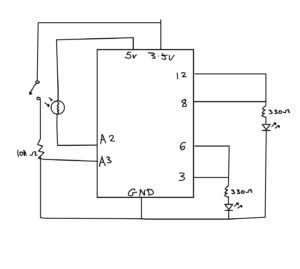
For my assignment, I initially wanted to have the LED lights off and then turn them on via the switch. Whilst holding the switch, I wanted to use the light sensor to change the brightness by hovering my finger over it. However, I couldn’t figure out how to use the light sensor whilst using a switch. It wasn’t working for me, unfortunately. So instead, I used the switch for blinking lights in sync and the light sensor to decrease the brightness whilst it is covered. For this, I needed: wires, resistors, a pushbutton, a light sensor, and LED lights.

I implemented the code we did in class for blinking and got help from this youtube video https://www.youtube.com/watch?v=d6xLaTxFVM4 to decrease the brightness via the light sensor.

This is the code I used for decreasing the light when the sensor is covered:

void loop() {
  // put your main code here, to run repeatedly:
  int buttonState = digitalRead(pushButton);
  ldr = analogRead(A0);
  brightness = map(ldr,0,1023,0,255);

   analogWrite(6, brightness);
   analogWrite(3, brightness);
}

Schematic Diagram:


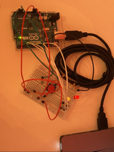
Project:


Future Improvements:

  • I’d like to do my original idea
  • I also would like the brightness of the LED light when the sensor isn’t covered to be brighter.
  • I’d also like to get more confident doing the schematic drawing as it did take me a while to figure it out.


Digital & Analog Switch

Concept 

I have inputed both an analog and digital switch to control two LEDs to the same bread board and using the same code. i wanted the digital switch to have a pattern with the red LED and that worked! i also wanted the light detector to turn on when it was dark and I was able to do that! IT was definitely a challenge working with the light detector since i had to rewrite my code a couple of times.

My code  

int buttonState = digitalRead(pushButton);

  if (buttonState == HIGH) {
    digitalWrite(redLEDPin, HIGH);
    delay(20);
    digitalWrite(redLEDPin, LOW);
    delay(300);
    digitalWrite(redLEDPin, HIGH);
    delay(20);
    digitalWrite(redLEDPin, LOW);
    delay(300);
    digitalWrite(redLEDPin, HIGH);
    delay(700);
  }
  allOff();
  delay(1000);

   analogValue = analogRead(LIGHT_SENSOR_PIN); // read the input on analog pin
 
  if(analogValue < ANALOG_THRESHOLD)
    digitalWrite(greenLEDPin, HIGH); // turn on LED
  else
    digitalWrite(greenLEDPin, LOW);
}

This is the main part of my code that controls both LEDs functions.

I tried to draw a circuit, Its not perfect but i enjoyed it

Arduino 

Improvement 

I would like to be able to use the analog switch better since I believe that I am not that a-custom to it yet. I also really want to tidy my breadboard for it to be more organized since I got lost with the wires sometimes


stop… go!


concept:

During this week’s exercise assignment, we were encouraged to explore Arduino and digital outputs such as the LED. As a result, I decided to delve into the delay function to make a traffic light system that accurately mimics the ones we see outside campus.


process:

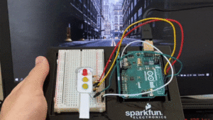
An essential element I intended to present was the creative aspect of the project. As a result, I ended up making a traffic light-like cut out in addition to previewing an image of a  street behind the Arduino to make it more realistic.


sketch: (click, wait till red lights blink to end)


future improvements:

Presenting an analog aspect would have been the next step, in the sense of adding a button that possibly controls two different traffic lights.

Assignment 6: Digital & Analog Sensors – The Street Lamp

Concept: 

For this assignment, I carried forward my concept from the last project. I wanted to make a circuit that included the use of a photoresistor, primarily because it could help me imitate a street lamp. As a child, I was always fascinated by street lamps and their magical tendency to somehow detect when it was dark and turn on.

The photoresistor could pick up environmental light levels and control one of the LEDs. However, I also wanted to enact the mental image of someone using a physical switch to control the lamps so that was also a conceptual integration

Implementation:

For the circuit for the light-dependant LED, I started put by connecting the LED in a pattern where the LDR would control the amount of voltage provided. My line of thinking was that I could in turn create a code that would give me light-level readings from the LDR and allow me to control the LED in real-time. However, I could not  figure out how to make it work so I decided to take inspiration from some sources;

LED Control with LDR (Photoresistor) and Arduino

Turn On & Off of LED with Photoresistor

After implementing the circuit, I was able to calibrate the code and modify it to fit the ambient light levels of my room. It allowed me to create a loop that runs constantly to detect the light and as soon as it drops below a certain level, it allows the LED to receive a charge and emit light.

The following code checks for the light levels and loops constantly and detect any changes in the light levels:

int ResistorStatus = analogRead(LDRPinNum);   //read the status of the LDR value

//check if the LDR status is more than/ equal to 500
//if it is, the LED is HIGH

 if (ResistorStatus <=500) {

  digitalWrite(LEDPinNum, HIGH);               //turns LED on
  Serial.println("It is  dark now, time for light");
  
 }
else {

  digitalWrite(LEDPinNum, LOW);          //turn LED off
  Serial.println(".............");
}

After this, I wanted to create a circuit and code that would control the button and the attached LED when the LDR circuit wasn’t working appropriately. For that, I used a code that would basically detect the state of the button and control the LED depending on that. if the button was pressed it would turn on and then a reversal statement would reverse the state of the button on the next press and turn the LED off.

The Diagram for the Circuit:

Video of the Project running:

Light-Sensitive Street Lamp Project Video Link

Reflection:

For this project, the main challenge was learning a seamless way to create unique code in C+. So far I have only dabbled in JS so this is a new experience for me but thankfully there are seemingly infinite resources online available for free for this. Additionally, I was also challenged by the hand-drawn diagram for my circuit. I think it took me way longer than it should have because I was scared of making mistakes but it seemed easier once I actually started making it. also, I’m glad I learned to draw circuits this way because it’s much more intuitive and takes less time than rendering it out on an editor.

also, one of the best things I learned during this exercise was that you can actually do cable management on Arduino! All you have to do is twist them into small loops. et voila! but i still have a ways to go lol

Analog and Digital sensors

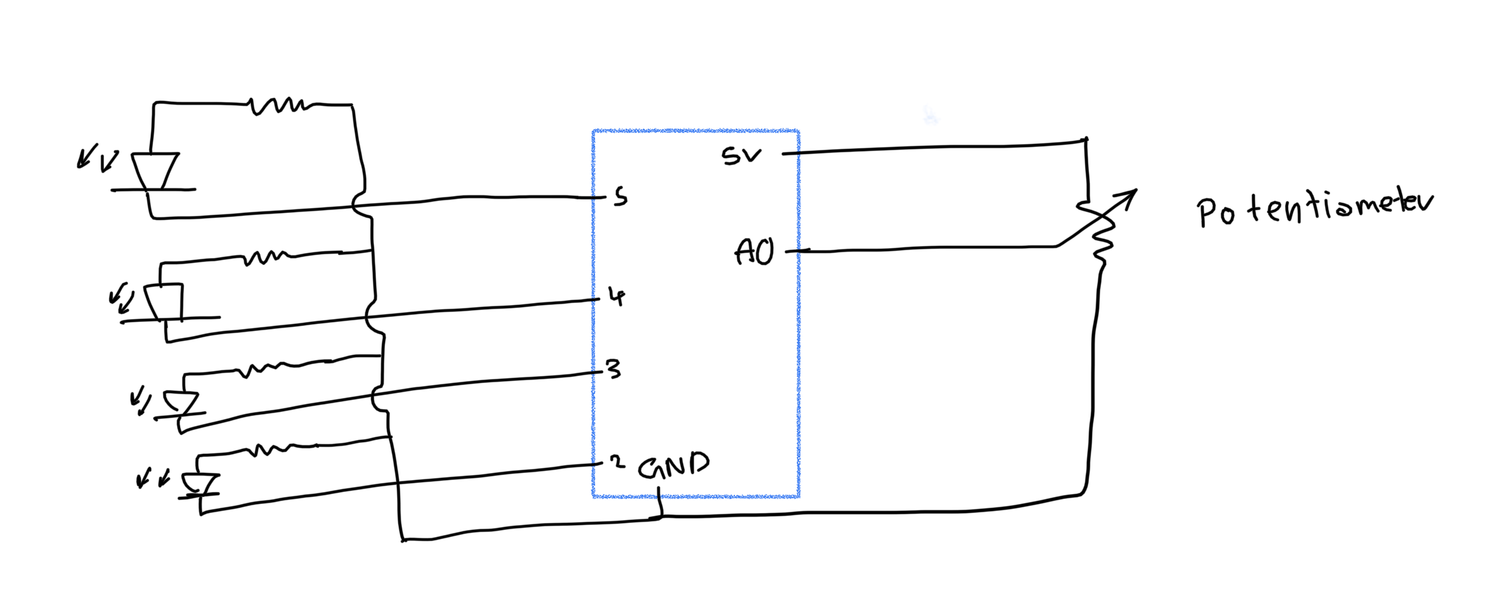
for this project I used the potentiometer to control which LED is turned on. I used mapping to map the sensor’s values to values between 2-5 (the LED pin numbers)

I used this snippet to turn the current LED on and turn the surrounding LEDs off.

digitalWrite((aSensor-1)%6, LOW);
digitalWrite(aSensor, HIGH);
digitalWrite((aSensor+1)%6, LOW);


here is how the circuit looked like (I accidentally drew this with the output to the left and input to the right unlike the convention)

here is a video of the LEDs

This video shows the LEDs without turning off the previous LEDs ((aSensor-1)%6)

I also wanted to use a pushbutton and a potentiometer to control an LED. I used the potentiometer to control how often the LED flickers (I used an array of values to control the brightness of the LED to make it look like it’s flickering) and I used the pushbutton to control if the LED turns on or off.

analogWrite(LED, flicker[current_ficker_value]*LED_on);
delay(aSensor);

The previous code takes a value from the array called flicker and multiplies that by LED_on. LED_on is a viable that equals 1 after the button is clicked and is set to 0. the potentiometer then sets the delay value (which is mapped between 30-100).
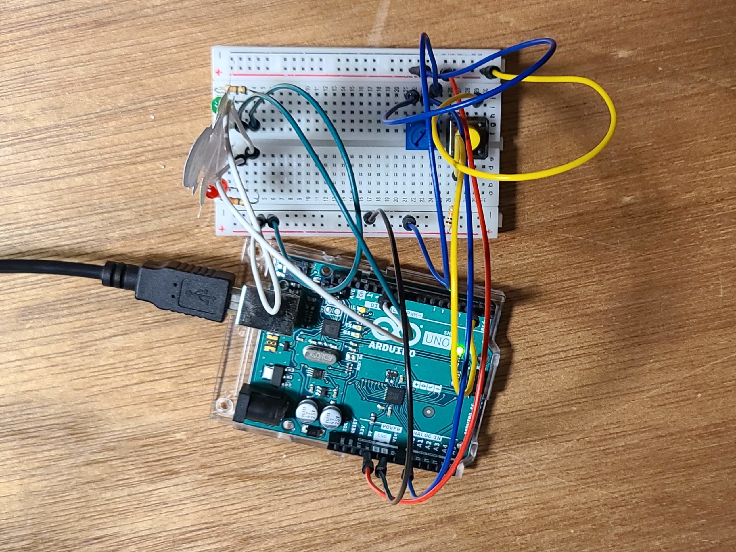
here is a picture of the circuit

here is a video of it running:

some things I tried but didn’t work:
    • tried to change the brightness of the LED by multipling the brightness Array by a certain franction but the numbers did not vary enough to show (becuase the fraction I multiplied with was too small(1.5 which is number that when multiplied by the largest number in the array returns 255))
    • I also tried to use a fucntion that takes a variable; whether the LED is on or off, and runs through the flicker array but I realized that becuase the I used a for loop to go through the flicker “stages” the response to the push button wasn’t being processed until the end of that for loop. this made it look like it wasn’t responsive
    • I finally decided to use a variable I increment in the loop function using (current_ficker_value = (current_ficker_value+1)%7;)

Digital and Analog Sensors

Concept

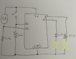
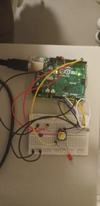
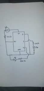
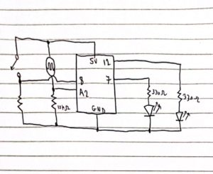
In this assignment, I built a circuit on the breadboard controlled by two sensors, a digital one and an analog one. The digital sensor is the button switch that controls the state of the red LED. The analog sensor is a light sensor that I designed to control the brightness of the green LED. I designed the circuit creatively so that the brightness of the red light will affect the light sensor and result in turning on the green light. Therefore, by just pressing the button, the user can see both the red and blue lights turned on. You can see the schematic for my project attached below.

leftmost resistor is also 10kOhms

In the schematic above you can see how I designed my circuit having the light sensor as an analog input that is being read by pin A2. and the switch as digital input that is being read by pin 8. Based on the values read by these pins I control the values produced by pin 12 and pin 7 which control the state of the two LED light outputs on the right. Here is the code that shows how I did this in Arduino.

void setup(){
  pinMode(8,INPUT);
  pinMode(7,OUTPUT);
  pinMode(A2,INPUT);
  pinMode(12,OUTPUT);
  Serial.begin(9600);
}

void  loop(){
  int switchState=digitalRead(8);
  int lightSensorInput=analogRead(A2);\
  Serial.println(lightSensorInput);
  delay(1);

  if(switchState==HIGH){
    digitalWrite(7,HIGH);

  }
  else{
    digitalWrite(7,LOW);

  }

  if(lightSensorInput>700){
    digitalWrite(12,HIGH);
  }
  else{
    digitalWrite(12,LOW);
  }

}

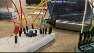
As you can see in the above code, the switch controls the state of the red LED. Then if the light sensor value is more that 700 then the green LED will turn on. Initially the light sensor values are not more than 620. However, I attached the red LED to be very close to the light sensor, so that when it is turned on, the value taken by the light sensor becomes greater than 700, hence the green LED light turns on. The result for this can be seen in the video below.

I really enjoyed creating this creative project, but I think it needs some improvements, especially in the way I did the wiring, I believe it needs to be more organized. To improve on this project, I might also add another light sensor to the other light and create an oscillating behaviour between the two lights.

Assignment 6: Analog and Digital Sensors

For this assignment, I thought of the game “Red light, Green Light”.  That also made me think of the Squid Game doll. Truthfully, I never watched Squid Game, but it was super viral and popular last year.

The Circuit and Code

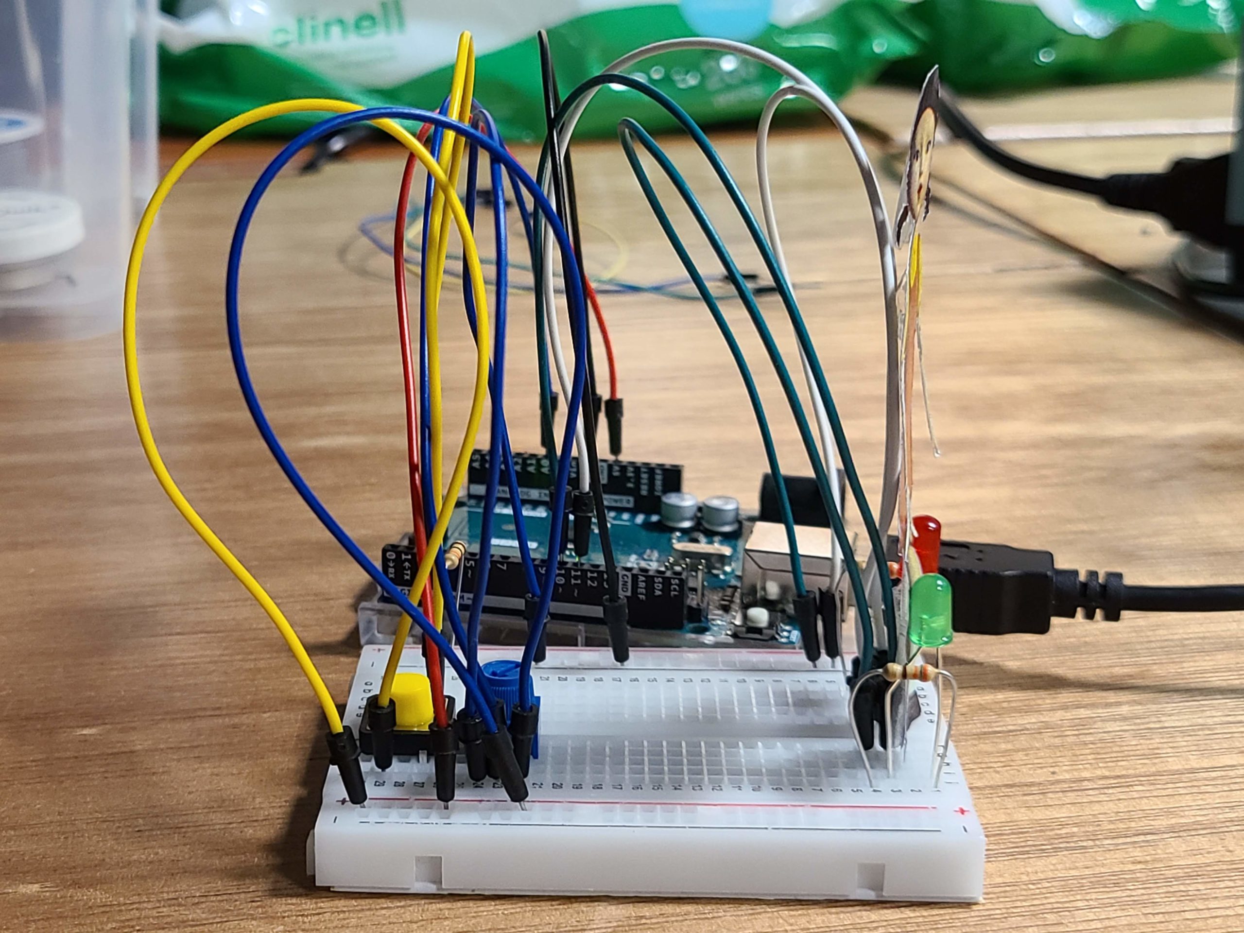
As Professor pointed out in class, I had everything super close on my breadboard. I did this for organizational purposes, but it ended up being the wrong choice because it was a bit difficult using the potentiometer (I rearranged it later but I didn’t take a new picture).

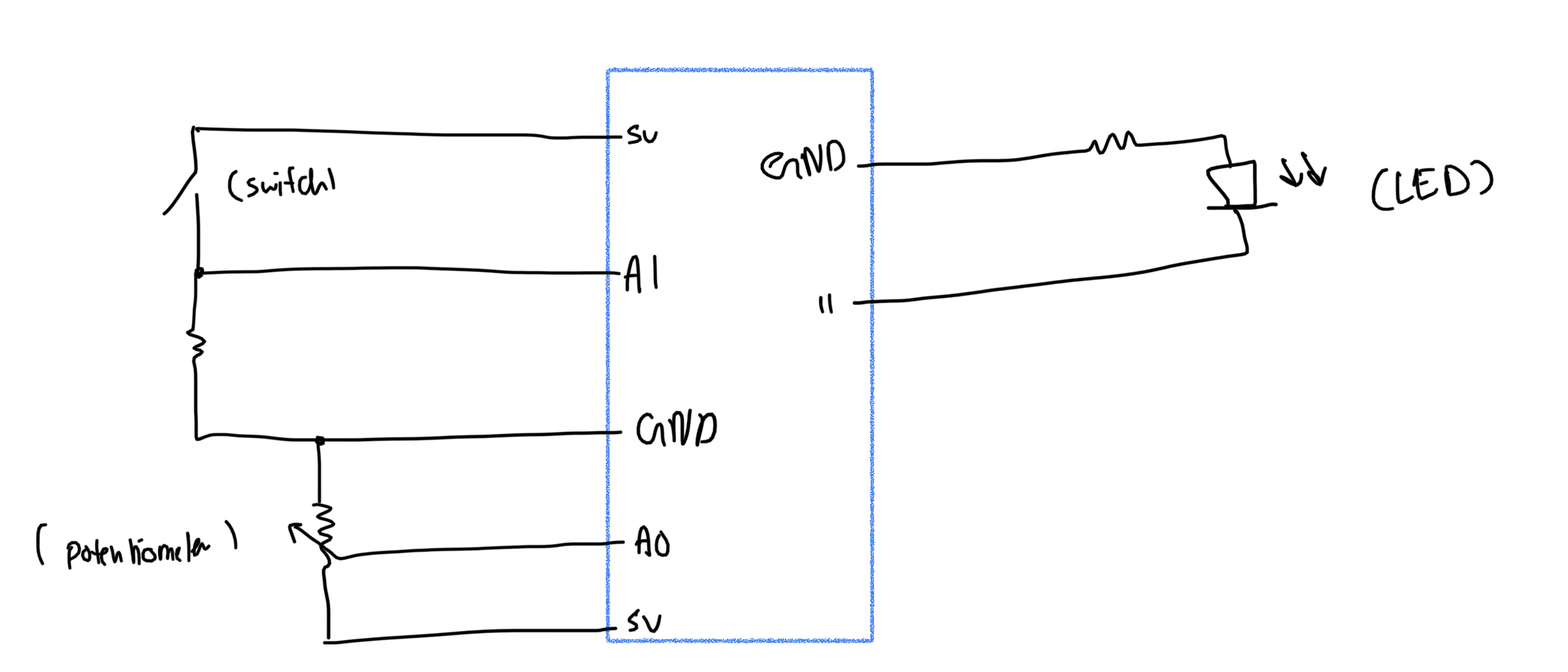
I tried drawing the schematic of my circuit:
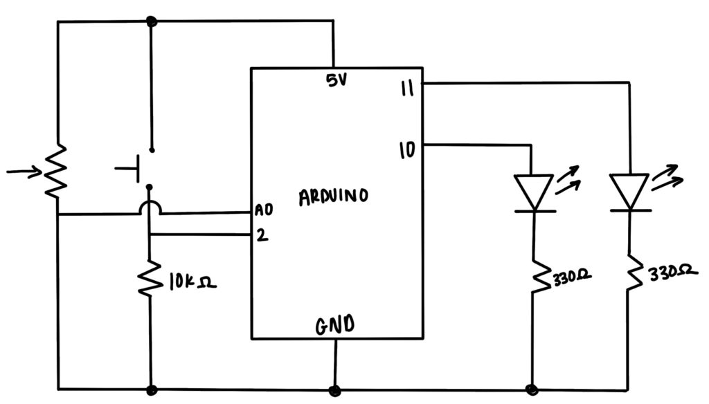
Basically I wanted to simulate Red Light, Green Light. So when the push button is pressed, the green light will go on first for a certain amount of time, which is determined by the potentiometer. Then the red light will go on and turn off after a random number of milliseconds.

int randomNumber = random(2000, 5000);
  int buttonState = digitalRead(PUSH_BUTTON);
  int potValue = analogRead(POT_PIN);
  int blinkSpeed = map(potValue, 0, 1023, 1000, 10000);

  // buttonState refers to the push button value; if it is pressed, it is HIGH (or 1)
  if (buttonState == HIGH) {
    digitalWrite(GREEN_LEDPIN, HIGH);
    digitalWrite(RED_LEDPIN, LOW);
    delay(blinkSpeed);
    digitalWrite(GREEN_LEDPIN, LOW);
    digitalWrite(RED_LEDPIN, HIGH);
    delay(randomNumber);
    digitalWrite(RED_LEDPIN, LOW);
  }

It’s a really simple program and I want to make it a longer and more randomized game. But this is what I have so far:

I made some adjustments to the program to make the LEDs turn on and off continuously, rather than once when the button is pushed. I got the code from this website, which explains how to turn a push button into a toggle switch. So in this version of my code, the LEDs turn on and off continuously. The speed at which they turn on and off is dependent on the potentiometer. The issue with this one is that it never stops, it just stays on the red LED unless you push the button again. This code does work better as a game, but there’s still a lot of room for improvement.

if (previousButtonState == 0 && currentButtonState == 1){
    if (LEDState == 0){
      digitalWrite(GREEN_LEDPIN, HIGH);
      digitalWrite(RED_LEDPIN, LOW);
      delay(blinkSpeed);
      digitalWrite(GREEN_LEDPIN, LOW);
      digitalWrite(RED_LEDPIN, HIGH);
      delay(blinkSpeed);
      LEDState == 1;
    }
    else{
      digitalWrite(GREEN_LEDPIN, LOW);
      digitalWrite(RED_LEDPIN, HIGH);
      LEDState = 0;
    }
  }
  
  previousButtonState = currentButtonState;
  delay(100);

Here is the video of how it works with the additional code:

Future Improvements

Again, I want to add more to this code, which involves randomizing which color is first and making it a longer game. Currently, I hard coded green to go first and then red goes, with the delay time determined by the potentiometer. It would also be cool if the first press of the button was starting the game, and then the next button press is stopping the game.