Exercise 1: Move a circle in P5Js using a single Arduino Sensor
Idea:
My idea was to simply use a potentiometer, since I wanted to practice serial connection between Arduino and P5JS. Since a potentiometer gives stable input, I thought it would be the best to use it to test the waters.
P5Js Code:
let ardVal = 0.0; // global variable to store the incoming data
let circleRad = 25;
function setup() {
  createCanvas(400, 400);
   frameRate(60);
}

function draw() {
  background(220);

  //map the input from arduino to the position of the circle
  let xPos = map(ardVal, 0, 1023, circleRad, width - circleRad);

  noStroke();
  fill(255,0,0); //red ball
  ellipse(xPos, 200, 2 * circleRad, 2 * circleRad);

  if(!serialActive)
  {
    print("Serial is not active");
  }

}

// to establish the serial connection
function keyPressed() {
  if (key == " ") {
    // important to have in order to start the serial connection!!
    setUpSerial(9600);
    print("SERIAL ACTIVATED");
  }
}

// how we read the incoming data
function readSerial(data) {

  if (data != null) {
    // make sure there is actually a message
    ardVal = data //read the incoming data as a float
    }
}
I wanted to display a simple red circle that moves across the screen based on the value of the potentiometer. Only the value of the potentiometer is sent from Arduino, and nothing is sent back to Arduino from P5Js.
Arduino Code:
#include <Arduino.h>

const int potInPin = A0;

void setup() {
  Serial.begin(9600); // 9600 bits per second
  pinMode(LED_BUILTIN, OUTPUT);
}

void loop() {
  int potValue = analogRead(potInPin);
  Serial.println(potValue);
}
The Arduino side of things is very simple. I read the value from the potentiometer and write it to the serial port.
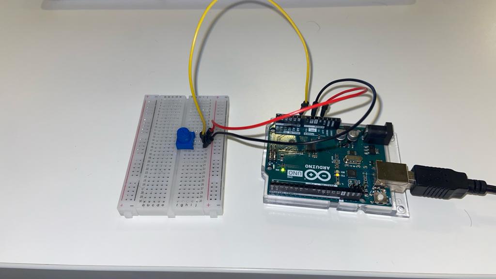
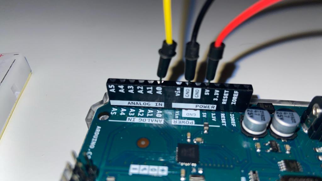
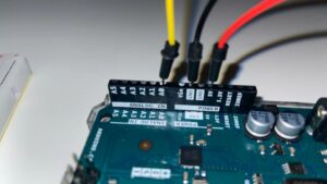
Circuit:
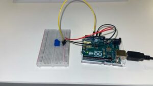
The circuit simply takes input from the potentiometer using the A0 pin.
Exercise 2: Move a circle in P5Js using a single Arduino Sensor
Note:
For this exercise, I had issues getting serial communication from P5Js to Arduino to work. I tinkered for a few hours, but then ended up finding this P5Js serial library that seems to be simpler to use, and I was able to get communication up and running with this. I will be using this library for future projects, and the rest of the exercises.
It can be imported via adding this to your P5Js sketch, in the index.html file:
<script src="https://unpkg.com/@gohai/p5.webserial@^1/libraries/p5.webserial.js"></script>
Idea:
Once I had communication running, the idea I (actually my friend who was watching me tinker) came up with was to create a sensor that would let you know where mines in minesweeper were. Thus, this LED would serve as a mine sensor. For this, I needed to create a simple minesweeper game, and add the functionality of detecting mines via the LED in the Arduino circuit.
Instead of making it a minesweeper game though, I decided to turn the game into that of a mouse trying to detect mines on the field. You can press “d” to defuse if you are on a mine. However, if you press “d” on the wrong mine, you lose a turn. The game is won if you defuse all the bombs, and lost if you try to defuse incorrectly too many times. The mouse can be controlled via the arrow keys.
Note: Please open the sketch in a new tab
P5Js Code:
It was very easy to create the port for connection. All I had to do was create a serial port object in the setup() function as follows:
function setup() {
  createCanvas(400, 500);
  //create a 2D array
  grid = create2DArray(numRows, numCols);

  //setup the grid cells
  for (let i = 0; i < numRows; i++) {
    for (let j = 0; j < numCols; j++) {
      grid[i][j] = new Cell(i, j, gridWidth / numRows, gridHeight / numCols);
    }
  }

  //place the mines
  placeMines();

  //create the mouse
  bombMouse = new Mouse();

  //create the serial port
  port = createSerial()

}
And then I asked the user to press space to begin the game, and pressing space asks the user to connect to the correct serial device, in this case our Arduino.
function keyPressed() {
  //to open the serial port
  if (key == " ") {
    if(port.opened())
    {
      return; //already opened
    }
    print("ACTIVATED");
    port.open(9600);
  }

  if (key == "d") {
    bombMouse.defuse();
  }

}
Finally, sending input to Arduino from P5Js is very simple as well:
let distance = bombMouse.distanceFromClosestBomb();

  let message = String(distance) + "\n";

  //send the distance to the arduino
  port.write(message);
  print(distance + "vs" + message);
I send the message as a string, and parse the integers from the string in Arduino.
The rest of the code for the game can be viewed on the P5Js web editor linked above.
Arduino Code:
The Arduino code for this was very simple. Parse distance through Serial.parseInt(), and then map it to brightness values. If the distance is 0, AKA mouse is on a mine, then the LED should blink.
#include <Arduino.h>

const int LED_PIN = 5;

int lastToggleTime = 0;
int currentStatus = LOW;

void setup()
{
  pinMode(LED_PIN, OUTPUT);
  Serial.begin(9600);
}

void loop()
{

  if(Serial.available() == 0)
  {
    //if no data is available, wait
    return;
  }

  //read distance from P5Js
  int distance = Serial.parseInt();

  if(distance == 0)
  {
    if(millis() - lastToggleTime < 30)
    {
      //if less than 1 second has passed, wait
      return;
    }
    lastToggleTime = millis();

    if(currentStatus == LOW)
    {
      currentStatus = HIGH;
    }
    else
    {
      currentStatus = LOW;
    }

    //if distance is 0, start blinking
    digitalWrite(LED_PIN, currentStatus);

  }

  else{

  //map distance to brightness but only show values between 0 and 3
  float brightness = map(distance, 0, 8, 255, 0); // max distance is 4 + 4 = 8

  //set brightness
  analogWrite(LED_PIN, brightness);
  }

}
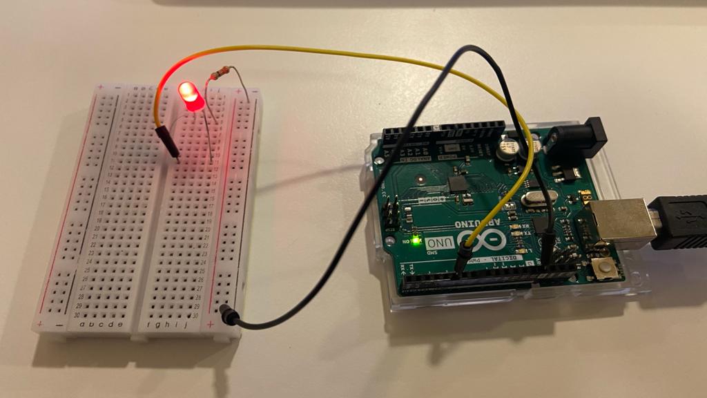
Circuit:
The circuit is a basic LED running circuit that takes input using a PWM pin (5).
Exercise 3:
This circuit takes input from the potentiometer to control the wind direction. Also, every time the ball hits the ground, a signal from P5Js is sent to Arduino so that the LED is turned on during the ball’s impact with the ground.
P5Js Code:
let velocity;
let gravity;
let position;
let acceleration;
let wind;
let drag = 0.99;
let mass = 50;

//port for arduino
let port;

function setup() {
  createCanvas(640, 360);
  noFill();
  position = createVector(width/2, 0);
  velocity = createVector(0,0);
  acceleration = createVector(0,0);
  gravity = createVector(0, 0.5*mass);
  wind = createVector(0,0);

  port = createSerial();
}

function draw() {
  if(!port.opened())
  {
    background(220, 200);
    fill(0);
    textSize(25);
    text("PRESS SPACE TO START", 50, height/2);
    return;
  }

  //read the serial port
  if(port.available())
  {
    let inString = port.readUntil('\n');
    let potVal = -1;
    if(inString.length > 0)
    {
      potVal = int(inString);
      wind.x = map(potVal, 0, 1023, -1, 1);

    }
  }

  print("WIND: " + wind.x);


  background(255);
  applyForce(wind);
  applyForce(gravity);
  velocity.add(acceleration);
  velocity.mult(drag);
  position.add(velocity);
  acceleration.mult(0);
  noStroke();
  fill(255,0,0);
  ellipse(position.x,position.y,mass,mass);
  if (position.y > height-mass/2) {
      velocity.y *= -0.9;  // A little dampening when hitting the bottom
      position.y = height-mass/2;

      //send a signal to arduino to turn on the LED
      port.write("1\n");
    }

  else{
    port.write("0\n");
  }

  //clear the buffer
  port.clear();


}

function applyForce(force){
  // Newton's 2nd law: F = M * A
  // or A = F / M
  let f = p5.Vector.div(force, mass);
  acceleration.add(f);
}

function keyPressed(){
  if (keyCode==LEFT_ARROW){
    wind.x=-1;
  }
  if (keyCode==RIGHT_ARROW){
    wind.x=1;
  }
  if (key==' '){
    mass=random(15,80);
    position.y=-mass;
    velocity.mult(0);
  }

  if(key == " ")
  {
    port.open(9600); // open a port at 9600 baud
  }
}
Arduino Code:
#include <Arduino.h>

const int ledPin = 5;
const int potPin = A0;

int timeSinceLastSerial = 0;


void setup() {
  pinMode(ledPin, OUTPUT);
  pinMode(potPin, INPUT);
  digitalWrite(ledPin, LOW); //initially off

  Serial.begin(9600);

}

void loop() {
  int val;

  if(millis() - timeSinceLastSerial < 2) //if it has not been more than 20ms since last serial message
  {
    return; //do nothing
  }

  timeSinceLastSerial = millis(); //update time since last serial message

  //serial exchange

  if(Serial.available()) //if there is data to read
  {
    val = Serial.parseInt(); //read the input from serial
  }

  if(val == 1)
  {
    digitalWrite(ledPin, HIGH); //turn on LED
  }
  else
  {
    digitalWrite(ledPin, LOW); //turn off LED
  }

  Serial.println(analogRead(potPin)); //send potentiometer value across serial

}
Circuit:
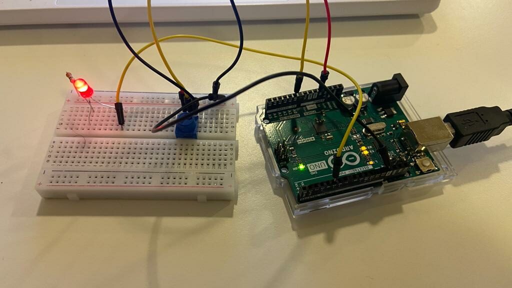
The circuit is a combination of the circuits from Exercises 1 & 2. There is a potentiometer whose value is read from Pin A0, and an LED powered by PWM pin 5 based on input from the P5Js sketch.
Video Demonstration: