Final Project – Mastermind

Concept

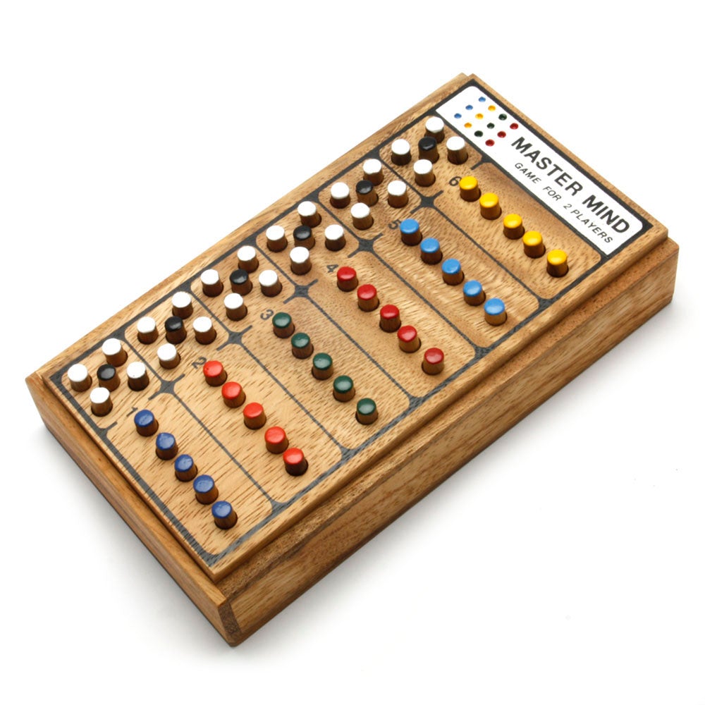
As I mentioned in a previous post, I wanted to make a Mastermind game, which is a two-player board game where one person is the code maker, and they make a code using colored pegs. The other person is the code breaker, and they have to figure out the code in a limited number of moves. The less moves you take to figure out the code, the higher you score.

Mastermind - Code Breaking Game – Kubiya GamesIn the version that I made, this game is actually a 1-player game, where the code is randomly generated, and the players have to guess the code. Players use a physical system of colored pegs and holes to parse input to the board.

Final Game

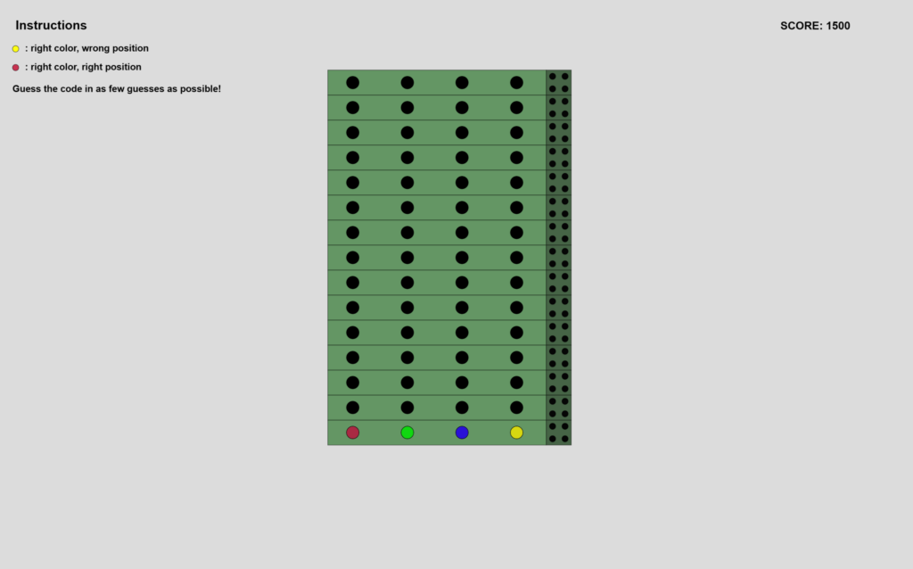
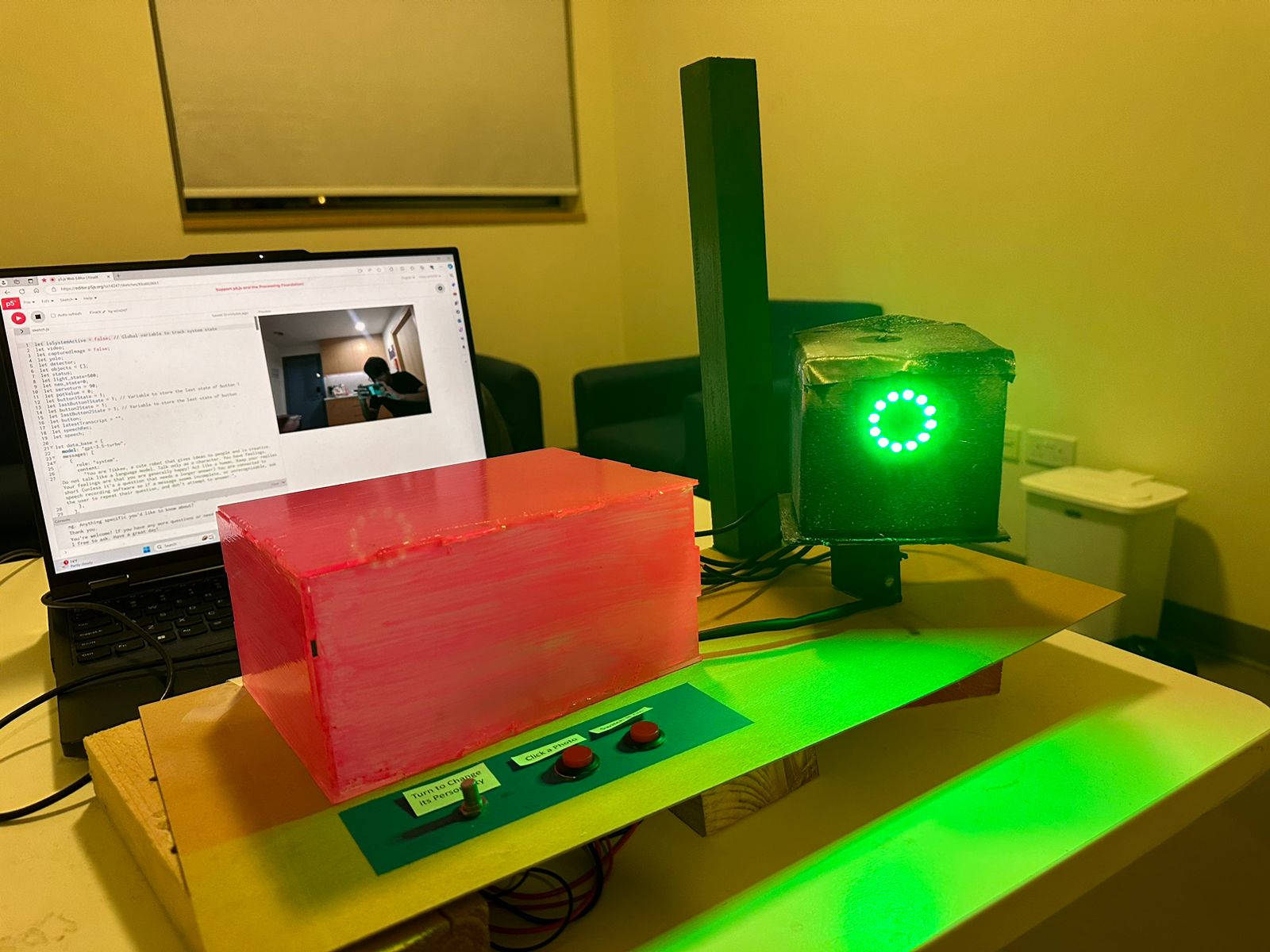
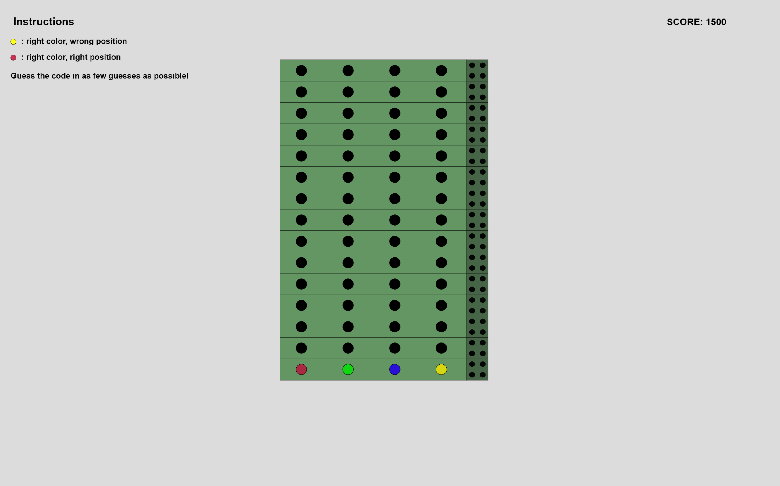
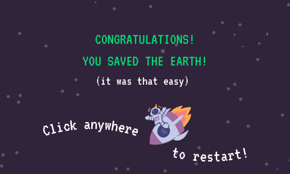
I’m very happy with the final P5Js interface for the game. It’s very minimalistic, which matches the style that I’ve chosen to go with for all of my projects. The instructions are in the upper left corner, as I didn’t want to clutter the interface by adding buttons to other pages. Also, I wanted to keep interaction with the laptop minimal if not zero, so I opted to have a static screen and focus on the physical input interface.

P5Js Sketch

The sketch does require a serial connection with Arduino. However, I enabled skipping the serial connection check for the purposes of viewing the sketch without an Arduino connection. You can press the “space” key to skip to the game screen. I have also edited the aspect ratio, for viewing it successfully within the Intro to IM blog post. It’s best viewed in fullscreen mode.
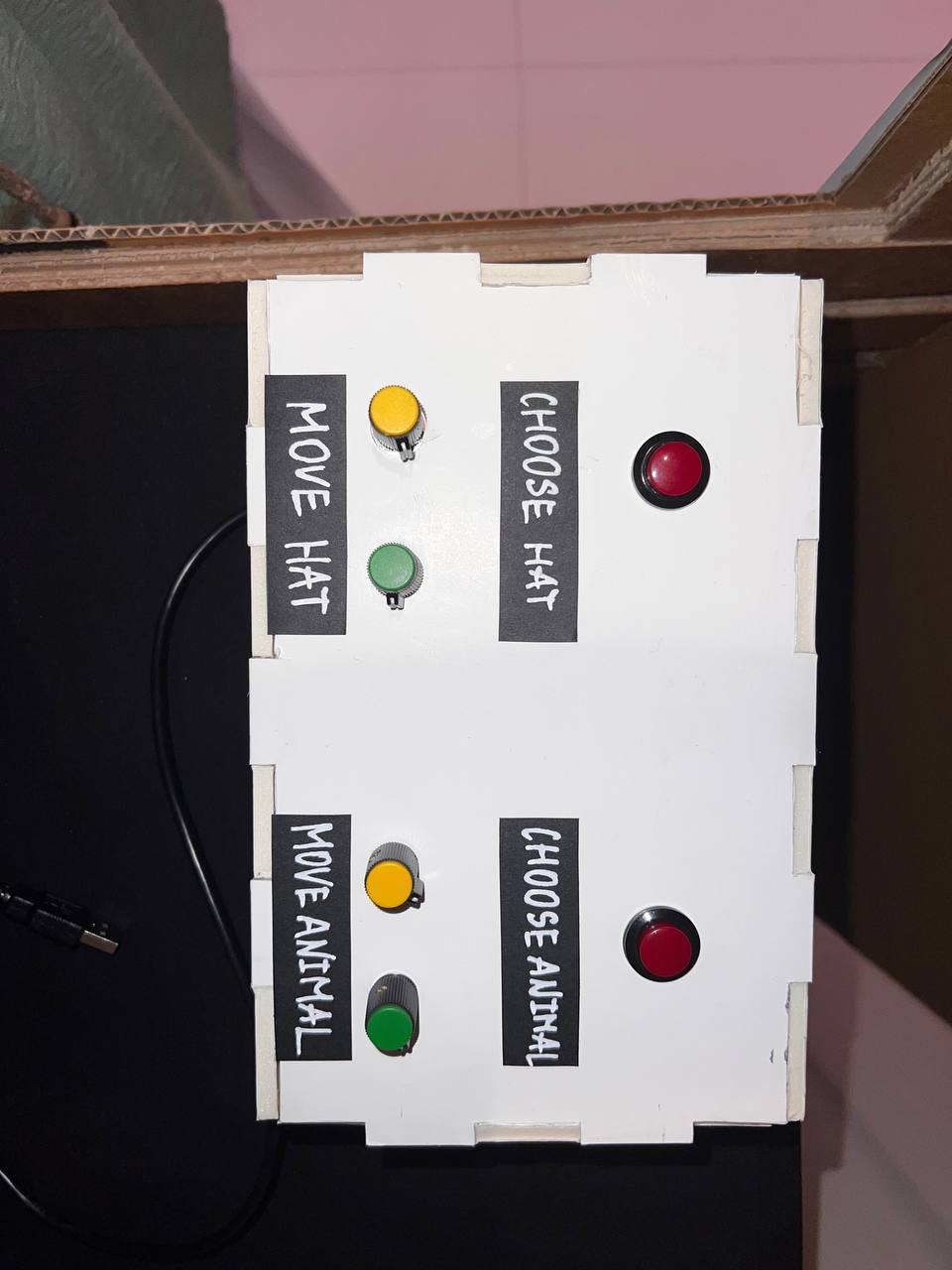
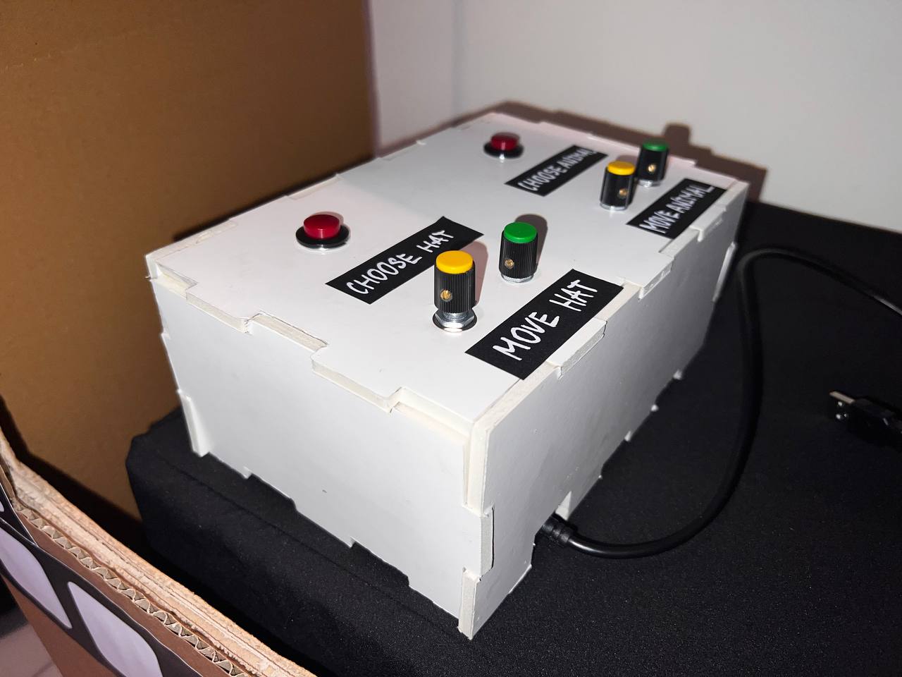
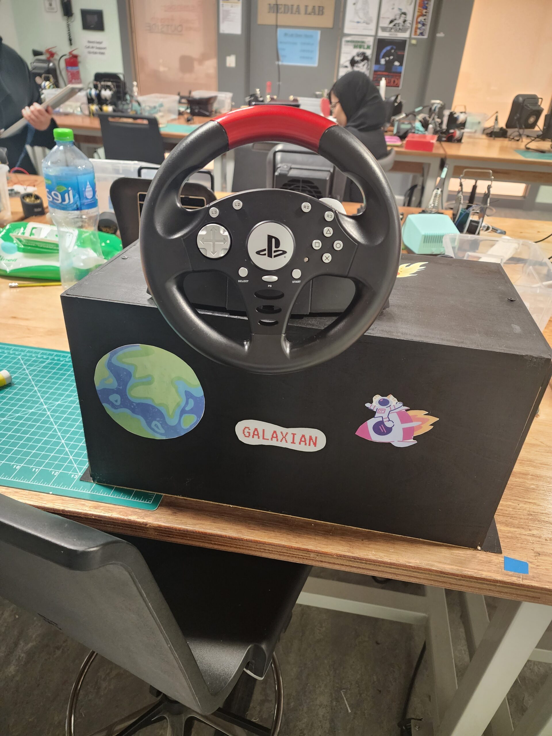
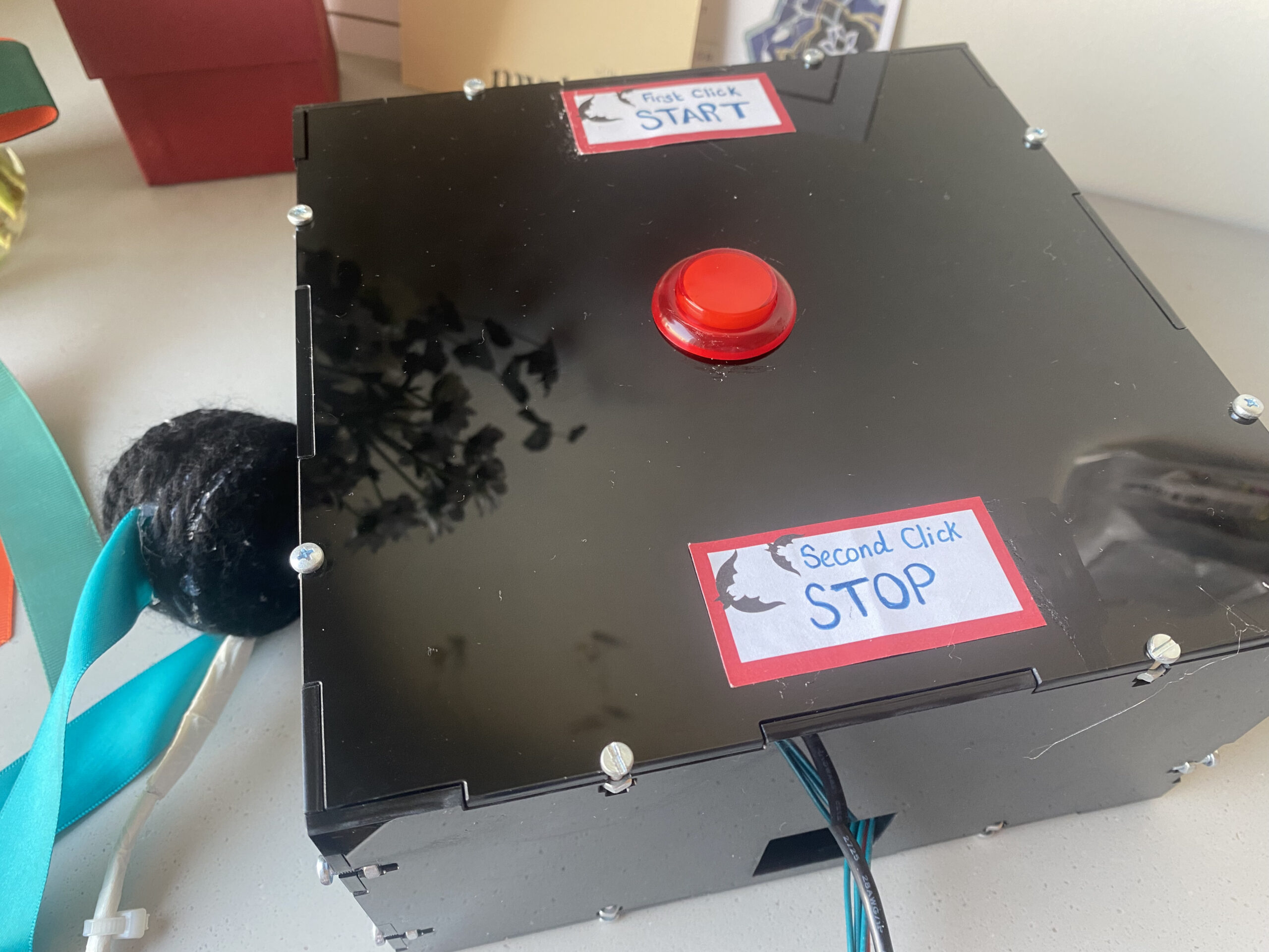
The Physical System

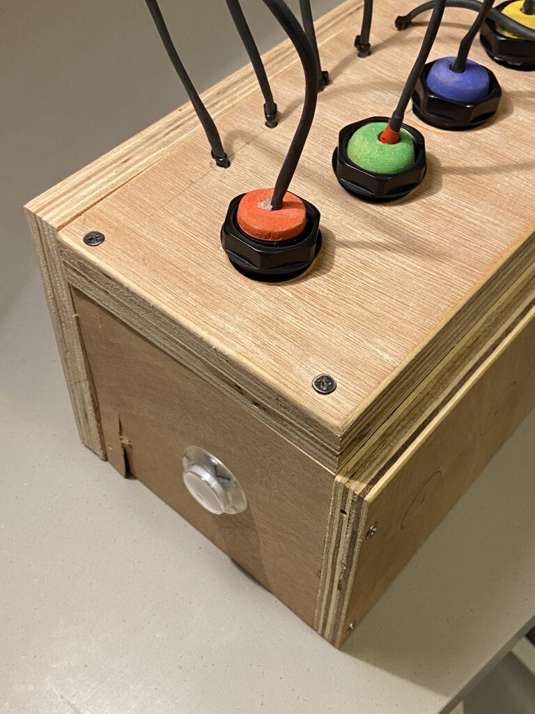
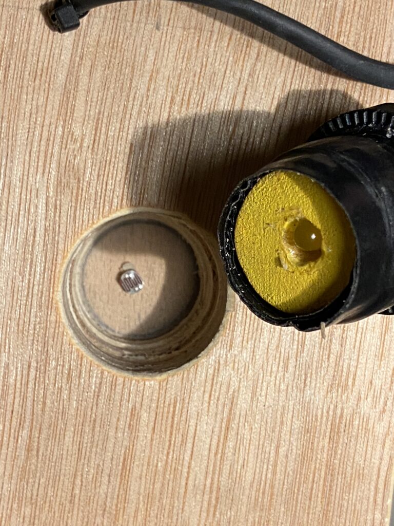
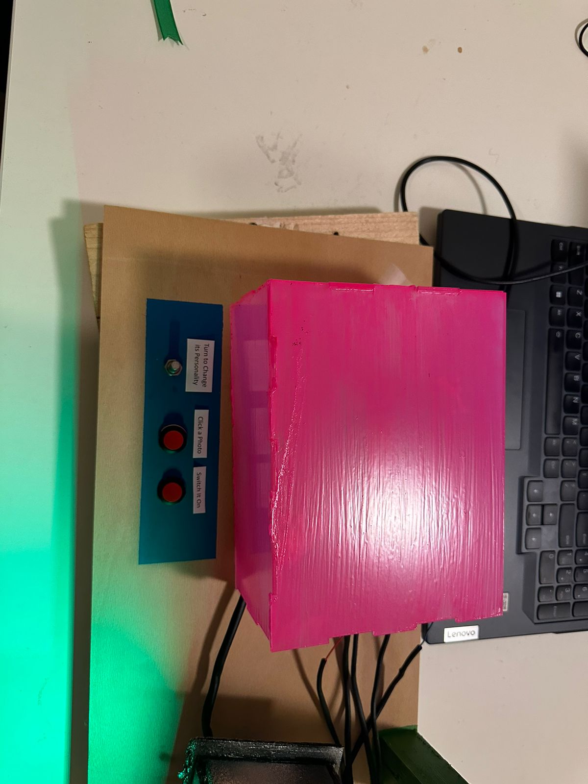
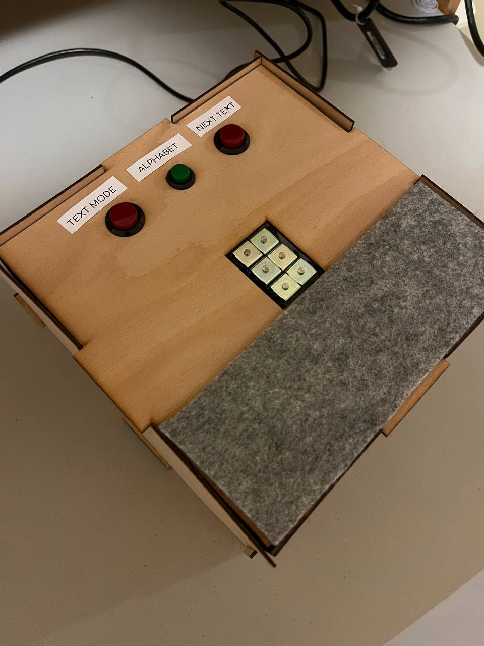
The control interface consists of a box with 5 colored pegs. In the picture below, you can see how the pegs fit into the console, and how the order can be changed to alter the input.


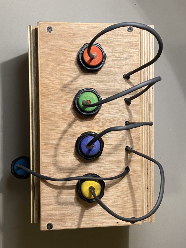
There is also a button on the left side of the interface, which can be pressed to confirm your choice. I used an LED momentary button because it reminded me of retro gaming consoles.

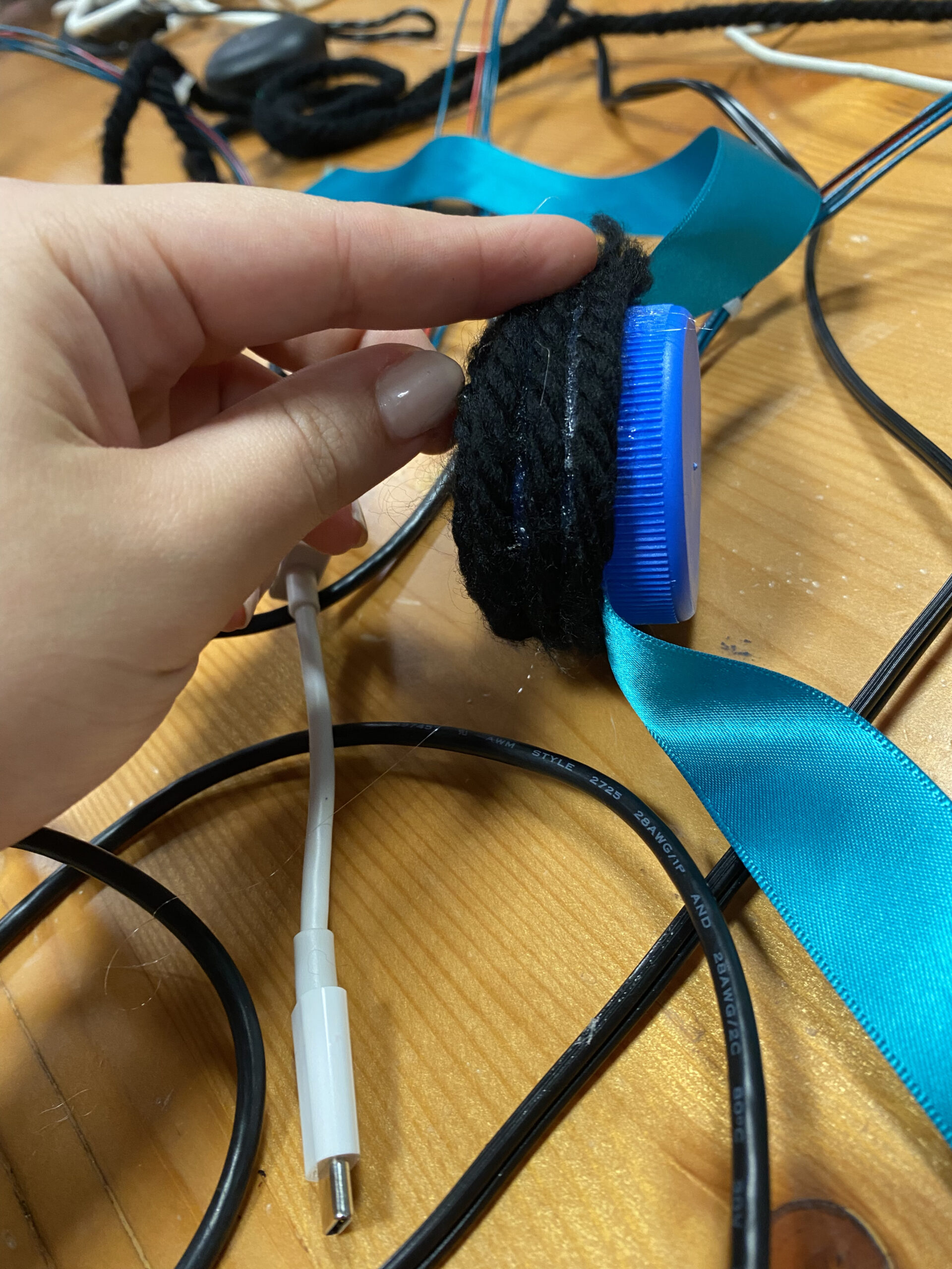
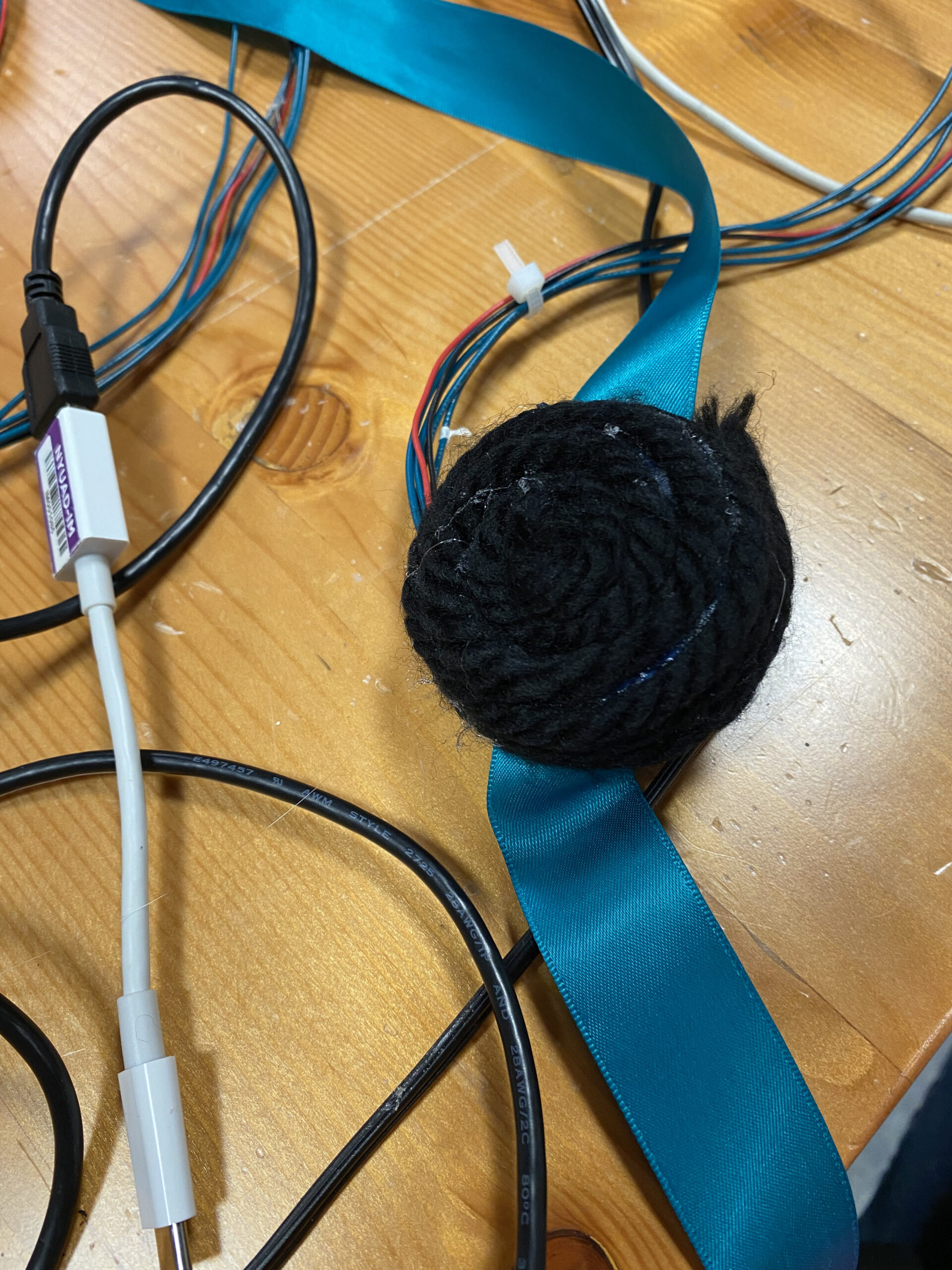
The color detection mechanism is rather naive, and it became a pain later on during the showcase as well. I have embedded LEDs in each peg, and each LED has a specific level of brightness. There is a single light sensor (LDR) in each of the 4 holes, which measures the brightness once a peg is placed into the hole. Depending on the brightness of the LED, a value corresponding to the respective color is generated. In the case of yellow, this would be the value “3”, which is the index in the array that contains the color values, as well as the index in which the pegs are fixed into the console, if you start counting from 0.

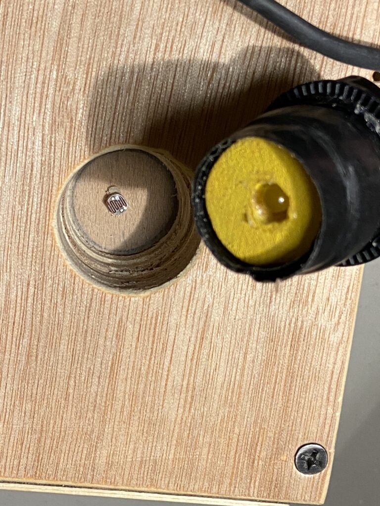
To ensure the fit was tight for consistent readings, I wrapped electrical tape around the pegs until there was a snug fit.

User Testing

I asked my friend to test the game for me. I told her nothing about how to use the interface, but she already knew about Mastermind.

She found the interface intuitive to use, but I think that it wasn’t as clear for people who didn’t know the game beforehand.

In the end, my friend won the game:
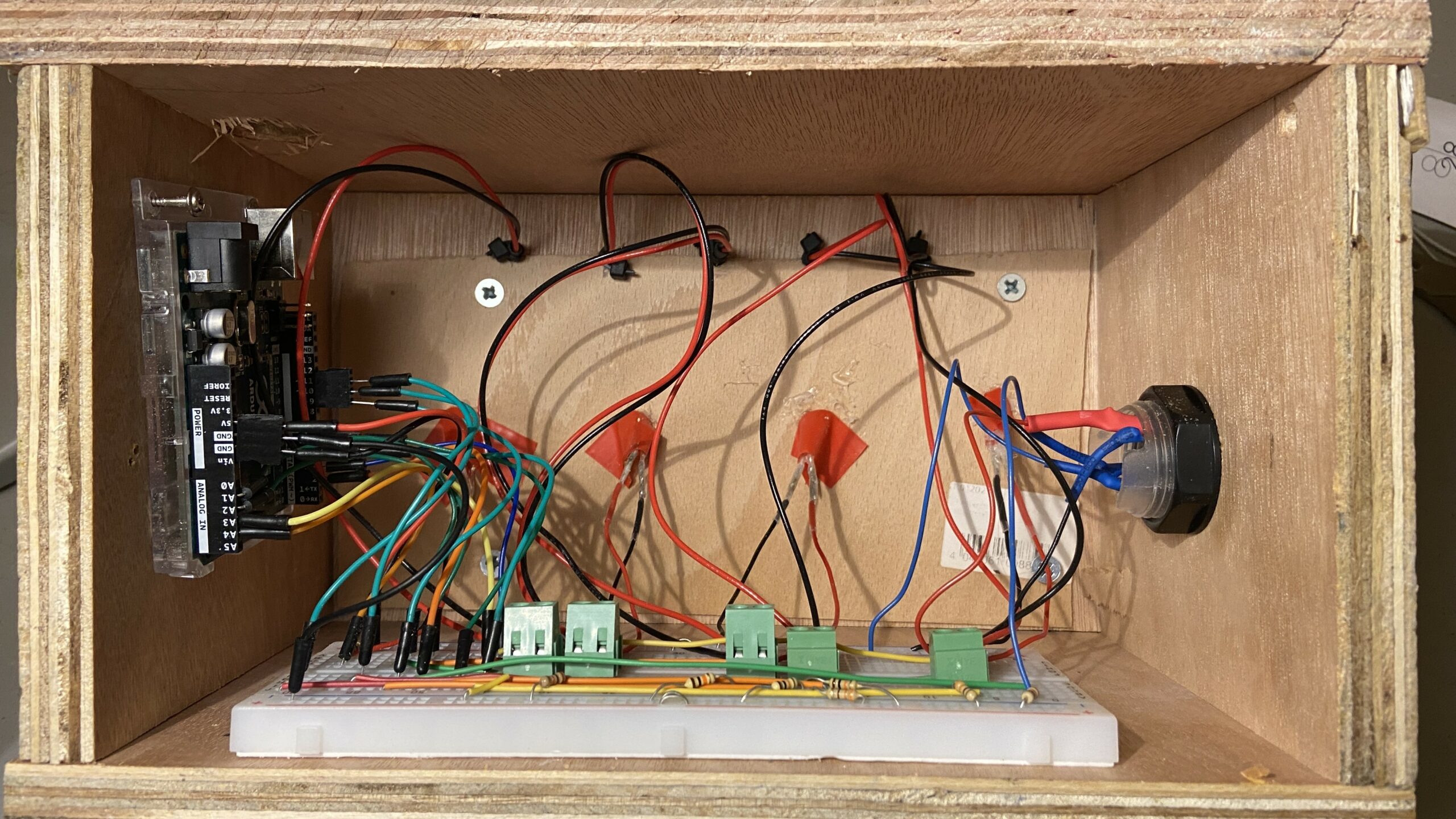
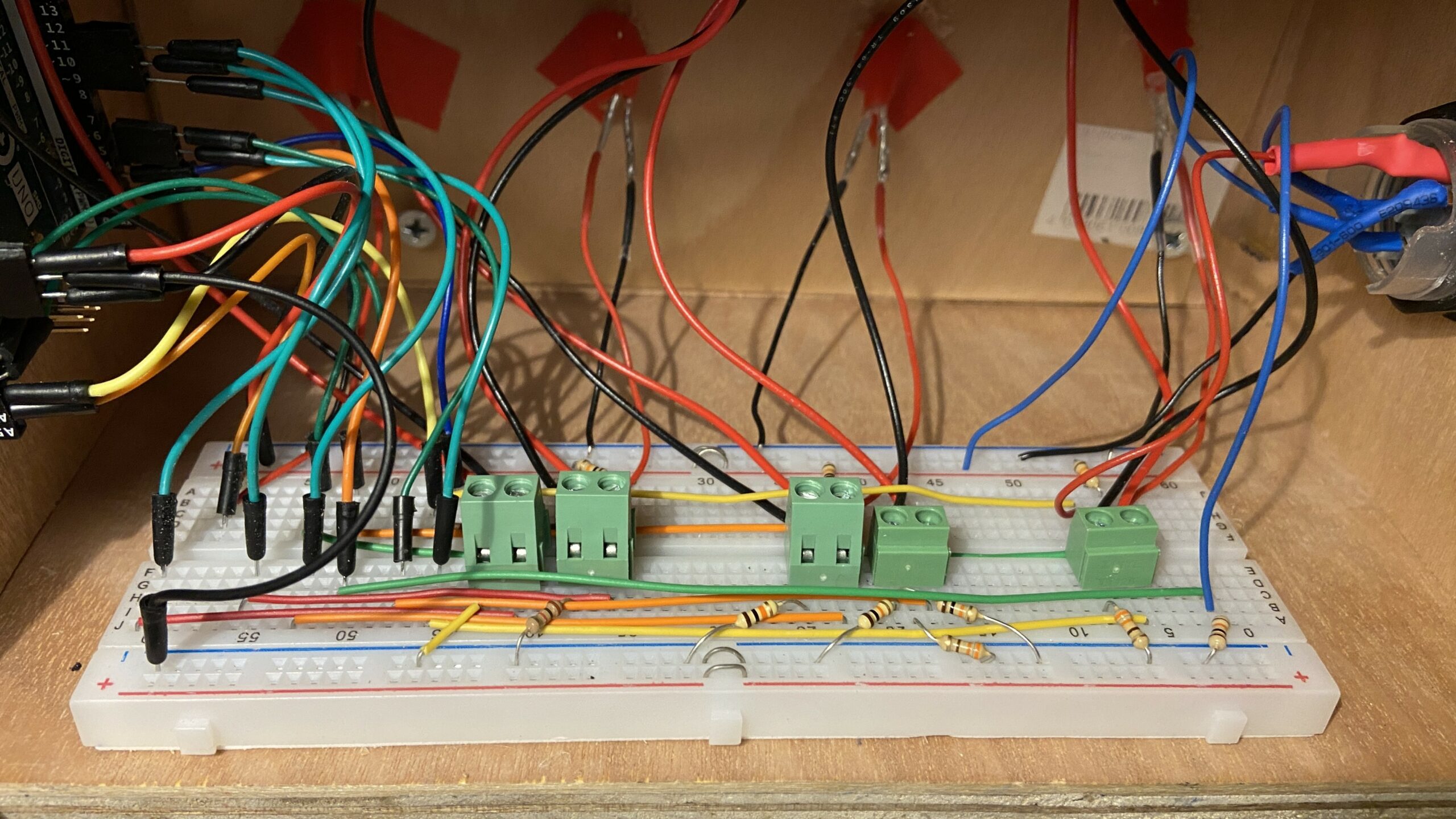
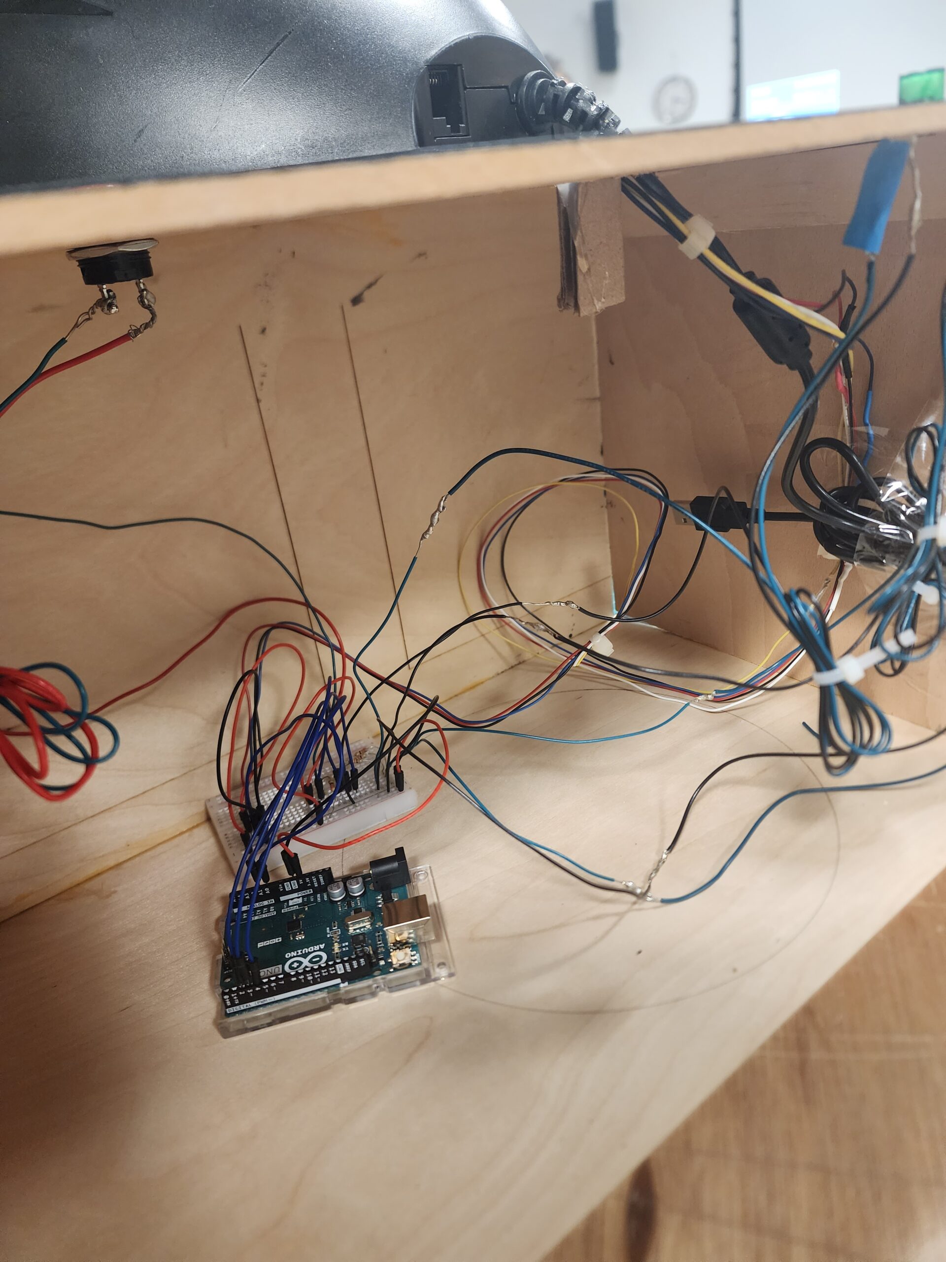
Circuit

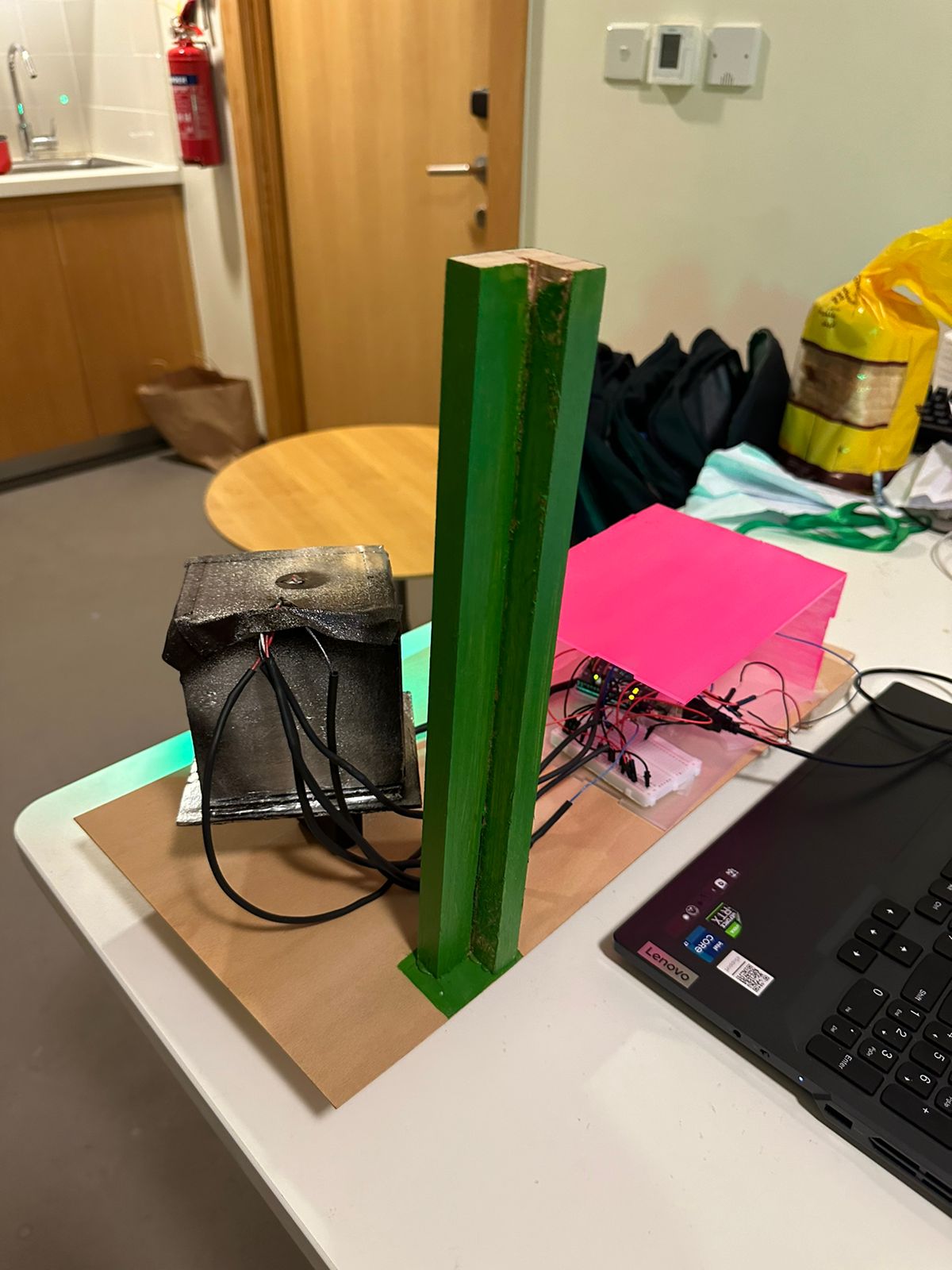
I wanted to keep the circuit as neat as possible, so I kept the Arduino on one side of the box, had a long breadboard in the middle, and the wires connecting to the closest part of the breadboard to the corresponding hardware. I then used jumper wires to complete the circuit on the breadboard.

I soldered the wires onto the LDRs and LEDs, and then use screw mounts to connect the other ends to the breadboard. I did the same for the LED button as well.

Communication Between P5Js and Arduino

I only implemented one way communication, as the goal was to have Arduino serve only as an input device. Therefore, I just sent the state of the current row of the game as an integer code, as well as a binary value showing whether or not the button to lock in the choice was pressed.

Challenges

The most challenging aspect was calibrating the LDRs and tuning them so that each color had a particular range. However, due to the sensitivity of the LDRs, it was hard to have the LDR value ranges for each color not intersect. There was a tradeoff, as if I chose to spread out the ranges for each color, it would mean that some colors would have the same brightness as the ambient brightness, which would end up showing that color throughout the board. I chose to keep this in for the sake of having more consistency in the input, but I realize that that decision made the game confusing for some people.

Aspects that I’m proud of

I really like the aesthetics of the game overall, and I think that the P5Js aspect of the project was done very well. There are definitely some features that I would have liked to implement, but the things that I chose to keep in were well done.

I’m also proud of the way I handled an issue that occurred. Since I’m using light sensors, the mechanism needed recalibration whenever the ambient brightness changed. To tackle this, I took two approaches.

Firstly, I took some plastic nuts from the large LED buttons and fixed them on top of the knobs to block out any light from the cracks around the knob. To make sure that there was absolutely no light coming through from around the peg, I wrapped it in tape until it fit snugly. This was the physical steps that I took.

Secondly, I created a calibration script within Arduino. When I needed to calibrate the settings, I would run this, and it would tell me what settings I need for the current environment based on the minimum and maximum readings for each color across all the light sensors. The code for that is below:

void calibrateColorRanges()
{
  Serial.println("Calibration started. Please follow the instructions to calibrate each color.");

  const int numColors = 5; // Assuming 5 colors: Red, Green, Blue, Yellow, Turquoise
  const int numLDRs = 4;   // Assuming 4 LDRs

  int calibrationValues[numColors][2]; // Array to store min and max values for each color across all LDRs

  for (int color = 0; color < numColors; color++)
  {
    Serial.print("Calibrating ");
    switch (color)
    {
    case 0:
      Serial.print("RED");
      break;
    case 1:
      Serial.print("GREEN");
      break;
    case 2:
      Serial.print("BLUE");
      break;
    case 3:
      Serial.print("YELLOW");
      break;
    case 4:
      Serial.print("TURQUOISE");
      break;
    }
    Serial.println("...");

    // Initialize min and max values
    calibrationValues[color][0] = 1023; // Initial min value
    calibrationValues[color][1] = 0;    // Initial max value

    for (int ldr = 0; ldr < numLDRs; ldr++)
    {
      Serial.print("Move ");
      switch (color)
      {
      case 0:
        Serial.print("RED");
        break;
      case 1:
        Serial.print("GREEN");
        break;
      case 2:
        Serial.print("BLUE");
        break;
      case 3:
        Serial.print("YELLOW");
        break;
      case 4:
        Serial.print("TURQUOISE");
        break;
      }
      Serial.print(" to LDR ");
      Serial.print(ldr + 1);
      Serial.println(" and press Enter.");

      // Wait for user input (press Enter in the Serial Monitor)
      while (!Serial.available())
      {
        delay(100);
      }

      // Discard any existing input
      while (Serial.available())
      {
        Serial.read();
      }

      // Perform readings and find min and max values
      for (int i = 0; i < 100; i++)
      {
        int ldrValue = analogRead(LDR_1 + ldr);

        // Update min and max values
        calibrationValues[color][0] = min(calibrationValues[color][0], ldrValue);
        calibrationValues[color][1] = max(calibrationValues[color][1], ldrValue);

        delay(10); // Delay between readings
      }
    }

    // Display the min and max values for the current color across all LDRs
    Serial.print("Min value: ");
    Serial.print(calibrationValues[color][0]);
    Serial.print(", Max value: ");
    Serial.println(calibrationValues[color][1]);
  }

  Serial.println("Calibration complete. Use the following values in getColorFromLdrVal function:");
  for (int color = 0; color < numColors; color++)
  {
    Serial.print("Color ");
    switch (color)
    {
    case 0:
      Serial.print("RED");
      break;
    case 1:
      Serial.print("GREEN");
      break;
    case 2:
      Serial.print("BLUE");
      break;
    case 3:
      Serial.print("YELLOW");
      break;
    case 4:
      Serial.print("TURQUOISE");
      break;
    }
    Serial.print(": Min - ");
    Serial.print(calibrationValues[color][0]);
    Serial.print(", Max - ");
    Serial.println(calibrationValues[color][1]);
  }
}

Although some other approach might have been more elegant, I think that I was able to manage even with the drawbacks of the design that I selected.

Future Ideas

  • I think it would be fun to add a leaderboard. Since I have score metrics already, it would be more fun if people competed against people who played the game previously.
  • It would be nice to have the option for players to play as codemakers as well, since the original game is a two-player game. That would make my project true to the original.
  • It would be better if I had the calibration embedded into the P5Js sketch, so that there is no need to reflash the Arduino. Currently, the way that I do it is to reflash the Arduino with the calibration command, and then flash it again after calibrating it, which is a nuisance.

Arduino Code

#include <Arduino.h>

// colors as ints
const int RED = 0;
const int GREEN = 1;
const int BLUE = 2;
const int YELLOW = 3;
const int TURQUOISE = 4;

// 5 LEDS with variable brightness on Arduino UNO
// LEDs are connected to pins 3, 5, 6, 9, 10
const int LED_PINS[] = {5, 6, 9, 10, 11};

const String colors[] = {"R", "G", "B", "Y", "T", "N"}; // red, green, blue, yellow, turquoise, none
// different brightness levels for LEDS
const int brightnessLevels[] = {LOW, HIGH, HIGH, HIGH, HIGH};
// const int brightnessLevels[] = {10, 0, 4, 153, 255};

// 4 LDRS connected to pins A1, A2, A3, A4
const int LDR_1 = A1; // 15
const int LDR_2 = A2; // 16
const int LDR_3 = A3; // 17
const int LDR_4 = A4; // 18

// 4 variables to store the values from the LDRs
int ldrValue1 = 0;
int ldrValue2 = 0;
int ldrValue3 = 0;
int ldrValue4 = 0;

// button LED
const int buttonLED = 3;
const int buttonPin = 2;

void setup()
{
  // initialize serial communication at 9600 bits per second:
  Serial.begin(9600);
  // initialize the LED pins as an output:
  for (int i = 0; i < 5; i++)
  {
    pinMode(LED_PINS[i], OUTPUT);
  }

  // initialize the LDR pins as an input:
  pinMode(LDR_1, INPUT);
  pinMode(LDR_2, INPUT);
  pinMode(LDR_3, INPUT);
  pinMode(LDR_4, INPUT);

  pinMode(buttonLED, OUTPUT);
  pinMode(buttonPin, INPUT_PULLUP);
}

const int minRed = 980;
const int maxRed = 1023;
const int minGreen = 610;
const int maxGreen = 940;
const int minBlue = 220;
const int maxBlue = 460;
const int minYellow = 120;
const int maxYellow = 220;
const int minTurquoise = 0;
const int maxTurquoise = 70;
int ambientLight[] = {0, 0, 0, 0};

int getColorFromLdrVal(int ldrVal, int ambientLight)
{
  if (ldrVal >= minRed && ldrVal <= maxRed) // range of
  {
    return RED;
  }
  if (ldrVal >= minGreen && ldrVal <= maxGreen) // range of 175
  {
    return GREEN;
  }
  if (ldrVal >= minBlue && ldrVal < maxBlue) // range of 310
  {
    return BLUE;
  }
  if (ldrVal >= minYellow && ldrVal <= maxYellow) // range of 70
  {
    return YELLOW;
  }

  if (ldrVal >= minTurquoise && ldrVal <= maxTurquoise) // range of 80
  {
    return TURQUOISE;
  }

  else
  {
    return 5;
  }
}

void calibrateColorRanges()
{
  Serial.println("Calibration started. Please follow the instructions to calibrate each color.");

  const int numColors = 5; // Assuming 5 colors: Red, Green, Blue, Yellow, Turquoise
  const int numLDRs = 4;   // Assuming 4 LDRs

  int calibrationValues[numColors][2]; // Array to store min and max values for each color across all LDRs

  for (int color = 0; color < numColors; color++)
  {
    Serial.print("Calibrating ");
    switch (color)
    {
    case 0:
      Serial.print("RED");
      break;
    case 1:
      Serial.print("GREEN");
      break;
    case 2:
      Serial.print("BLUE");
      break;
    case 3:
      Serial.print("YELLOW");
      break;
    case 4:
      Serial.print("TURQUOISE");
      break;
    }
    Serial.println("...");

    // Initialize min and max values
    calibrationValues[color][0] = 1023; // Initial min value
    calibrationValues[color][1] = 0;    // Initial max value

    for (int ldr = 0; ldr < numLDRs; ldr++)
    {
      Serial.print("Move ");
      switch (color)
      {
      case 0:
        Serial.print("RED");
        break;
      case 1:
        Serial.print("GREEN");
        break;
      case 2:
        Serial.print("BLUE");
        break;
      case 3:
        Serial.print("YELLOW");
        break;
      case 4:
        Serial.print("TURQUOISE");
        break;
      }
      Serial.print(" to LDR ");
      Serial.print(ldr + 1);
      Serial.println(" and press Enter.");

      // Wait for user input (press Enter in the Serial Monitor)
      while (!Serial.available())
      {
        delay(100);
      }

      // Discard any existing input
      while (Serial.available())
      {
        Serial.read();
      }

      // Perform readings and find min and max values
      for (int i = 0; i < 100; i++)
      {
        int ldrValue = analogRead(LDR_1 + ldr);

        // Update min and max values
        calibrationValues[color][0] = min(calibrationValues[color][0], ldrValue);
        calibrationValues[color][1] = max(calibrationValues[color][1], ldrValue);

        delay(10); // Delay between readings
      }
    }

    // Display the min and max values for the current color across all LDRs
    Serial.print("Min value: ");
    Serial.print(calibrationValues[color][0]);
    Serial.print(", Max value: ");
    Serial.println(calibrationValues[color][1]);
  }

  Serial.println("Calibration complete. Use the following values in getColorFromLdrVal function:");
  for (int color = 0; color < numColors; color++)
  {
    Serial.print("Color ");
    switch (color)
    {
    case 0:
      Serial.print("RED");
      break;
    case 1:
      Serial.print("GREEN");
      break;
    case 2:
      Serial.print("BLUE");
      break;
    case 3:
      Serial.print("YELLOW");
      break;
    case 4:
      Serial.print("TURQUOISE");
      break;
    }
    Serial.print(": Min - ");
    Serial.print(calibrationValues[color][0]);
    Serial.print(", Max - ");
    Serial.println(calibrationValues[color][1]);
  }
}

unsigned long timeSinceLastSerial = 0;
int valFromP5 = 0;

float sum1, sum2, sum3, sum4 = 0;
unsigned int ldrVal1, ldrVal2, ldrVal3, ldrVal4 = 0;
unsigned int iterator = 0;

unsigned long buttonLEDTimer = 0;
unsigned long buttonSendTimer = 0;

int buttonBrightness = 0;
int buttonDirection = 1;

int buttonState = LOW; // if button is not pressed

void loop()
{

  // fade in and out button LED
  if (millis() - buttonLEDTimer > 5)
  {
    buttonLEDTimer = millis();
    if (buttonBrightness >= 255 || buttonBrightness <= 0)
    {
      buttonDirection = buttonDirection * -1;
    }

    buttonBrightness = (buttonBrightness + 1 * buttonDirection);
    if (buttonBrightness >= 255)
    {
      buttonBrightness = 255;
    }
    if (buttonBrightness <= 0)
    {
      buttonBrightness = 0;
    }
    analogWrite(buttonLED, buttonBrightness);
  }

  // turn on the LEDs to the corresponding brightness
  digitalWrite(LED_PINS[RED], brightnessLevels[RED]);
  digitalWrite(LED_PINS[GREEN], brightnessLevels[GREEN]);
  digitalWrite(LED_PINS[BLUE], brightnessLevels[BLUE]);
  digitalWrite(LED_PINS[YELLOW], brightnessLevels[YELLOW]);
  digitalWrite(LED_PINS[TURQUOISE], brightnessLevels[TURQUOISE]);

  // uncomment to calibrate color ranges
  // calibrateColorRanges();

  // send to processing
  if (millis() - timeSinceLastSerial < 10) // if it has not been more than 20ms since last serial message
  {
    return; // do nothing
  }

  timeSinceLastSerial = millis(); // update the time since last serial message

  if (iterator == 10)
  {
    ldrVal1 = int(sum1 / 10);
    ldrVal2 = int(sum2 / 10);
    ldrVal3 = int(sum3 / 10);
    ldrVal4 = int(sum4 / 10);

    // print the values if they are not nan
    if (!isnan(ldrVal1) && !isnan(ldrVal2) && !isnan(ldrVal3) && !isnan(ldrVal4))
    {

      // get the color from the LDR value
      int color1 = getColorFromLdrVal(ldrVal1, ambientLight[0]);
      int color2 = getColorFromLdrVal(ldrVal2, ambientLight[1]);
      int color3 = getColorFromLdrVal(ldrVal3, ambientLight[2]);
      int color4 = getColorFromLdrVal(ldrVal4, ambientLight[3]);
      int buttonState = digitalRead(buttonPin);

      Serial.print(color1);
      Serial.print(",");
      Serial.print(color2);
      Serial.print(",");
      Serial.print(color3);
      Serial.print(",");
      Serial.print(color4);
      Serial.print(",");
      Serial.println(buttonState);
    }

    iterator = 0;
    sum1 = 0;
    sum2 = 0;
    sum3 = 0;
    sum4 = 0;
  }

  // read and add values from the LDRs
  sum1 = sum1 + analogRead(LDR_1);
  sum2 = sum2 + analogRead(LDR_2);
  sum3 = sum3 + analogRead(LDR_3);
  sum4 = sum4 + analogRead(LDR_4);

  iterator++;
}

P5Js Code

let board;

let WIDTH = 2800;
let HEIGHT = 1500;
let colorsArray;

const RED = 0;
const GREEN = 1;
const BLUE = 2;
const YELLOW = 3;
const TURQUOISE = 4;
const BLACK = 5;

let canvas;
let port;

let highScores = [];


function generateCode() {
 let code = [];
  let array = [0, 1, 2, 3 , 4, 5];
  //select random subset of 4 colorsArray
  let colorsArray = shuffleArray(array);

  for (let i = 0; i < 4; i++) { // select only 4 colorsArray
    code.push(colorsArray[i]);
  }

  return code;
}

// Helper function to shuffle an array
function shuffleArray(array) {
  //copy the array
  array_copy = array.slice();

  for (let i = array_copy.length - 2; i > 0; i--) {
    const j = Math.floor(Math.random() * (i + 1));
    [array_copy[i], array_copy[j]] = [array_copy[j], array_copy[i]];
  }
  return array_copy;
}


function calculateScore(numGuesses) {
  return 1500 - 100 * numGuesses;
}

let r, g, b, y, t, bl;


let currentGuess;
let numberOfGuesses;
let lastButtonPressed;
let isButtonPressed;
let buttonClock;
let board_score;
let state;


function setup() {
  canvas = createCanvas(WIDTH, HEIGHT);
  board = new Board();

  r = color(200, 50, 80);
  g = color(20, 255, 20);
  b = color(50, 20, 255);
  y = color(255, 255, 20);
  t = color(20, 255, 255);
  bl = color(0, 0, 0);


  // colorsArray are red, green, blue, yellow, turquoise, black
  colorsArray = [r, g, b, y, t, bl];

  //generate the code
  code = generateCode();

  port = createSerial();

  //initialize important variables
  numberOfGuesses = 0;
  lastButtonPressed = 0;
  isButtonPressed = 0;
  buttonClock = 0;

  board_score = [0, 0];

  state = "AUTH_STATE";

}

function resetGame()
{
  board.reset();
  numberOfGuesses = 0;
  score = 0;
  state = "AUTH_STATE";
  code = generateCode();

}


function getNameInput()
{
  let name = prompt("Please enter your name ");
  if (name == null || name == "") {
    name = "Anonymous";
  }
  return name;
}


let delayClock = 0;
function draw() {

  if (state == "GAME_STATE") {
    background(220);

    board_score = board.score;
      print("score: " + board_score);

      if (board_score[0] == 4) {
        print("GAME WON")
        state = "GAME_WON_STATE";

        delayClock = millis();
      }

      if (board.currentRow == 15) {
        print("GAME LOST")
        state = "GAME_LOST_STATE";
        delayClock = millis();

      }

    // if the port is open, read the data
    if (port.available() > 0) {
      let data = port.readUntil("\n");

      split_data = int(data.split(","));

      // first 4 are the current guess
      // last is the button press
      currentGuess = split_data.slice(0, 4);
      isButtonPressed = split_data[4];
      board.update(currentGuess);
    }


    //if the button is pressed, finalize the guess
    if (isButtonPressed == 1 && lastButtonPressed == 0) {
      if (board.finalizeChoices(code))
      {
        numberOfGuesses++;
      };
      lastButtonPressed = 1;
    }

  
    else if (isButtonPressed == 0 && lastButtonPressed == 1) {
      lastButtonPressed = 0;
    }


    board.show();

    //show the score at the top right
    fill(0);
    textSize(35);
    push();
    textStyle(BOLD);
    text("SCORE: " + calculateScore(numberOfGuesses), width - 300, 100);
    pop();

    // print instructions to the side 
    fill(0);
    textSize(40);

    push();
    textStyle(BOLD);
    text("Instructions", 50, 100);
    pop();

    textSize(30);
    
    push(); 
    fill(y);
    circle(50, 162, 20);
    pop();
    text(": right color, wrong position", 80, 170);

    // red circle 
    push();
    fill(r);
    circle(50, 222, 20);    
    pop();

    text(": right color, right position", 80, 230);

    text("Guess the code in as few guesses as possible!", 40, 300);


  }

  else if (state == "GAME_WON_STATE") {
    background(220, 200);
    fill(0);
    textSize(60);
    textStyle(BOLD);
    text("YOU WON!", width / 2 - 200, height / 2);

    //SHOW SCORE
    fill(0);
    textSize(35);
    push();
    textStyle(BOLD);
    text("SCORE: " + calculateScore(numberOfGuesses), width / 2 - 200, height / 2 + 100);
    pop();


    if (millis() - delayClock < 2000) {
      return;
    }


    //read input from the serial port
    if (port.available() > 0) {
      let data = port.readUntil("\n");
      
      data = int(data.split(","));

      let buttonval = data[4];
      if (buttonval == 1) {
        print("resetting");
        board.reset();
        numberOfGuesses = 0;
        state = "GAME_STATE";
        board_score = [0, 0];
      }
    }
  }

  else if (state == "GAME_LOST_STATE") {
    background(220, 200);
    fill(0);
    textSize(60);
    textStyle(BOLD);
    text("YOU LOST!", width / 2 - 200, height / 2);

    text("The code was: ", width / 2 - 600, height / 2 + 200);
    //print the right code
    for (let i = 0; i < 4; i++) {
      push();
      fill(colorsArray[code[i]]);
      circle(width/2 - 100 + i * 100, height/2 + 185, 50);
      pop();
    }

    //push the button to reset
    push();
    textSize(30);
    text("Press the button to reset", width / 2 - 200, height / 2 + 400);
    pop();


    if (millis() - delayClock < 2000) {
      return;
    }

    //read input from the serial port
    if (port.available() > 0) {
      let data = port.readUntil("\n");
      
      data = int(data.split(","));

      let buttonval = data[4];
      if (buttonval == 1) {
        print("resetting");
        resetGame();
      }
    }
  }


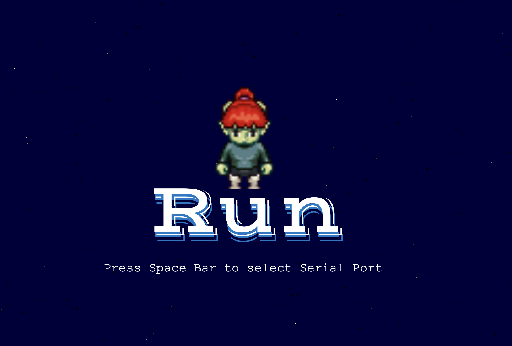
  else if (state == "AUTH_STATE") {

    //ask to connect to the device
    background(220, 200);
    fill(0);
    textSize(60);
    textStyle(BOLD);
    text("PRESS SPACE TO START", width / 2 - 300, height / 2);

    if(port.opened()) {
      state = "GAME_STATE";
    }

  }


}


/**
 * Handles key press events and performs corresponding actions.
 */
function keyPressed() {
  /**
   * If the key pressed is "c" and the state is "GAME_STATE",
   * finalize the choices on the board using the provided code.
   *
   * @returns {void}
   */
  if (key == "c") {
    if (state != "GAME_STATE") {
      return;
    }
    board.finalizeChoices(code);
  }
}

  /**
   * If the key pressed is "n", update the current color of the current row on the board.
   * The color is updated by incrementing the current color index by 1 and wrapping around to 0 if it exceeds 5.
   *
   * @returns {void}
   */
  if (key == "n") {
    board.rows[board.currentRow].currentColor = (board.rows[board.currentRow].currentColor + 1) % 6;
  }

  /**
   * If the key pressed is " " (space) and the state is "AUTH_STATE",
   * open a port at 9600 baud using the port object.
   *
   * @returns {void}
   */
  if (key == " ") {
    if (state != "AUTH_STATE") {
      return;
    }
    port.open(9600);
  }

  /**
   * If the key pressed is "r", reset the game.
   *
   * @returns {void}
   */
  if (key == "r") {
    resetGame();
  }
}

Week 11 Final project idea

My final project idea is to develop an immersive and interactive surfing simulator game. The idea came to me when I went to the arcade and saw a snowboarding game and it sparked my interest to know how it was made and if I could replicate it with something I enjoyed and miss which is surfing. This game will use a physical skateboard found in the IM lab equipped with an accelerometer to capture the player’s movements, and a P5.js-based game that simulates a surfing and will have the concept of collecting and avoiding.


This is the inspiration below:

Extreme Snowboard – Toggi Fun World

Week 11- Nourhane’s Reading Response

Reading Graham Pullin’s “Design Meets Disability” was like opening a window to a new world of possibilities in design. Pullin’s approach is transformative, merging concepts like simplicity, universality, exploratory problem-solving, fashion, and discretion into a cohesive vision for disability aids. He challenges the traditional, function-first mindset and proposes a more inclusive, style-conscious approach, arguing that assistive devices should be as much a statement of personal style as they are functional.

Pullin’s ideas are inspiring, urging us to think beyond the conventional. He’s not just talking about making things easier to use but also about embracing the diversity of users. His call for a blend of aesthetics and functionality in design resonates with me. It’s a fresh take that adds dignity and choice to the equation, offering people with disabilities more than just practical solutions but also products they can feel good about using.

However, as a student thinking critically, I see challenges in Pullin’s vision. His idealistic approach makes me wonder about the real-world implications. How do we balance these ambitious design goals with practical constraints like cost, manufacturing complexities, and the varied needs of individuals with disabilities? It’s one thing to dream of stylish, universally accessible designs, but another to implement them in a way that’s affordable and accessible to all.

“Design Meets Disability” has definitely broadened my understanding of what design can and should do. It’s pushed me to think about how we can make the world more inclusive through thoughtful design. But it’s also left me with questions about the balance between idealism and feasibility. How do we make these innovative designs a reality for everyone who needs them, not just those who can afford them? It’s a challenging question, and Pullin’s book is a compelling starting point for this important conversation.

FINAL PROJECT – Photo Booth : Design your ID card

CONCEPT

As I mentioned before, for my final project I decided to create an engaging experience for anyone on our campus at NYUAD to design their new ID card. This is supposed to tackle two aims: 1) bring joy and fun to people who are using the program; 2) allow people to be creative and design a card that suits their character.

At the very beginning, during the development of the idea, one of my classmates mentioned that my idea reminded them of a photo booth. This became the main concept of the experience. I constructed a real photo booth, to which people can come, sit down and take their selfies, as they like. If they do not like the picture, they can take it again as many times as they want, until they are satisfied with the result. So, this project would address the issue of dissatisfaction with ID card photos through the feature of capturing their images in real-time.

Then, participants can write whatever name they want on their new ID card. Sometimes people do not like the name that appears on their passport, which unfortunately they cannot change. However, in this project, I am giving them this opportunity.

Then, the fun part begins. Users can choose from a variety of images to be displayed on their ID. I have two categories: ANIMALS and HATS. They can choose whatever image they want by pressing buttons. Moreover, they can position them anywhere on their ID badge. This aims to enhance the individuality of their IDs.

Finally, they can save an image of their ID, which I will, of course, send to them afterward. So, this project seeks to not only address practical concerns but also provide a unique and enjoyable experience for users.

IMPLEMENTATION
Interaction Design 

This is a P5 setup in the beginning:

After you connect to the port by pressing the “/” key, and you press ENTER to take a snapshot, two images appear (animal and hat images).

You can go through an array of images by pressing the red buttons and choosing the hat and animal that you like. Further, you can adjust their position with potentiometer knobs. You can write your name in the input text box and SUBMIT it by clicking the button, so it appears as usual text on the ID badge. Finally, if you are satisfied with everything, you can click the CAPTURE button and save the ID badge.

The final ID badge image looks like this:

Set up during the show:

I have developed my concept further and designed a photobooth from cardboard. I printed out instructions and the table for people to fill in (where they would write their name and net ID, so I can send them the image of the ID badge later). I have designed this box from large cardboard pieces that I found in the lab. Painted the front with black acrylic paint and printed a design that reminds me of the film. 

Process:

Another part of my project is a small white box that I built from foamboard, which holds two red buttons, 4 potentiometer knobs (yellow for the X axis and green for the Y axis), and labels for them. I have designed this box in the Maker Case.  Then I used a ruler and box cutter to cut all the parts and assemble them. They fit nicely, but I additionally used some glue to be sure the box can hold the pressure from pressing buttons and rotating knobs. 

Process:

During the process of building these parts, the biggest challenge was cutting the elements. I did not have an opportunity to use a laser cutter, therefore I spent lots of time cutting and taping everything by hand.

P5 code

Most of the time was spent setting up the P5 sketch. What does it do? The P5 program starts with a display of an ID badge. I design these with primitive rectangular shapes and text. I wanted to include instructions on the screen. however, I did not want to overcomplicate the appearance of the sketch, so I decided to do it on an A3 paper. However, as I noticed not many were reading instructions presented behind the laptop, therefore, it would be better to present them on the screen.

On the P5, participants were presented with a live video which is the size of a snapshot they are about to make. As they press ENTER, the snapshot selfie replaces the live video. This was a very challenging part of the code. However, with some help, I was able to do this. Here is the portion of the code that I used as an example:

let capture;

function setup() {
  createCanvas(500, 500);
  capture = createCapture(VIDEO);
  capture.hide();
}

function draw() {
  let aspectRatio = capture.height/capture.width;
  
  image(capture, 0, 0, width, width * aspectRatio);
  filter(INVERT);
}

As soon as the photograph is taken, and if it is taken,  the signal to Arduino is sent, so it can now send communication to P5. P5 then acts as a receiver and displays different images of hats and animals. Moreover, participants can type their name in the input box and submit it to be displayed on the screen. Finally, by clicking capture they can save their ID cards. This is all done with built-in boxes and buttons in P5.

It was hard to figure out the logic that I wanted my program to have. But finally, I managed to do a set of nested if statements which I am very proud of. This is a part of the code that allows you to go in an array of images and select their position.

 if (snapshot) {
    // Display a captured selfie in place of the live video
    // resizing to the same parameters as video

    image(snapshot, width / 2, height / 2 - 100, 220, 180);

    // A nested if statement:
    // if -1 then no hat image is selected, otherwise the statement is true.
    // If a hat image is selected, then display the image at the index selectedHat from the array of hatImages.
    // The image is placed at coordinates (hatX, hatY).

    if (selectedHat !== -1) {
      image(hatImages[selectedHat], hatX, hatY);
    }

    // A nested if statement:
    // if -1 then no animal image is selected, otherwise the statement is true.
    // If an animal image is selected, then display the image at the index selectedAnimal from the array of animalImages.
    // The image is placed at coordinates (animalX, animalY).

    if (selectedAnimal !== -1) {
      image(animalImages[selectedAnimal], animalX, animalY);
    }
  }
}
Final Code for P5- embedded sketch: 
Arduino Code

Setting up the Arduino code was pretty easy. I used only the information we learned in class.   The code consists of the declaration of 2 buttons, 4 potentiometers, and their states. The state of each button and the potentiometer is read and sent to p5.  The part that I am proud of is mapping the potentiometer values to the desired range of the canvas. This was a very important part of the Arduino code because, with this, users were able to adjust the position of hat and animal images.

  • When pressing the HAT button, which is a digital input on pin 2, participants will see an image of a hat. They can choose their hat by pressing the button again.
  • Then participants will need to adjust the position of a hat using 2 potentiometers that also operate on 2 potentiometers, which are analog inputs and located on pins A0 and A1.
  • They can also do the same actions to choose their favorite animal by pressing the ANIMAL button. They can also select an appropriate location using two potentiometers, which are analog inputs and located on pins A2 and A3.
Final code for Arduino: 
const int buttonHatPin = 2;        // Pin for the hat button
const int buttonAnimalPin = 3;     // Pin for the animal button
const int potentiometerHatXPin = A0;  // Pin for the X-axis potentiometer for hat
const int potentiometerHatYPin = A1;  // Pin for the Y-axis potentiometer for hat
const int potentiometerAnimalXPin = A2;  // Pin for the X-axis potentiometer for animal
const int potentiometerAnimalYPin = A3;  // Pin for the Y-axis potentiometer for animal

int buttonHatState = 0;       // Current state of the hat button
int buttonAnimalState = 0;    // Current state of the animal button
int potentiometerHatXValue = 0;  // Current value of the X-axis potentiometer hat
int potentiometerHatYValue = 0;  // Current value of the Y-axis potentiometer hat
int potentiometerAnimalXValue = 0;  // Current value of the X-axis potentiometer animal

int potentiometerAnimalYValue = 0;  // Current value of the Y-axis potentiometer animal

void setup() {
  Serial.begin(9600);               // Initialize the serial communication
  pinMode(buttonHatPin, INPUT);     // Setting up the button pin as input
  pinMode(buttonAnimalPin, INPUT);  // Setting up the button pin as input


  // START THE HANDSHAKE TO SEND 6 VALUES FROM ARDUINO TO P5
  while (Serial.available() <= 0) {
    digitalWrite(LED_BUILTIN, HIGH);  // on/blink while waiting for serial data
    Serial.println("0,0,0,0,0,0");    // send a starting message
    delay(300);                       // wait 1/3 second
    digitalWrite(LED_BUILTIN, LOW);
    delay(50);
  }
}

void loop() {
  buttonHatState = digitalRead(buttonHatPin);           // Read the state of the hat button
  buttonAnimalState = digitalRead(buttonAnimalPin);     // Read the state of the animal button
  potentiometerHatXValue = analogRead(potentiometerHatXPin);  // Read the value of the X-axis potentiometer for hat image
  potentiometerHatYValue = analogRead(potentiometerHatYPin);  // Read the value of the Y-axis potentiometer for hat image
  potentiometerAnimalXValue = analogRead(potentiometerAnimalXPin);  // Read the value of the X-axis potentiometer for animal image
  potentiometerAnimalYValue = analogRead(potentiometerAnimalYPin);  // Read the value of the Y-axis potentiometer for animal image


  // Map the potentiometer values to the desired range
  int hatX = map(potentiometerHatXValue, 0, 1023, 0, 900);  // Map X-axis potentiometer value to the canvas width
  int hatY = map(potentiometerHatYValue, 0, 1023, 0, 900);  // Map Y-axis potentiometer value to the canvas height

  int animalX = map(potentiometerAnimalXValue, 0, 1023, 0, 900);  // Map X-axis potentiometer value to the canvas width
  int animalY = map(potentiometerAnimalYValue, 0, 1023, 0, 900);  // Map Y-axis potentiometer value to the canvas height

  // Send the button states and potentiometer values to p5.js
  Serial.print(buttonHatState);
  Serial.print(",");
  Serial.print(buttonAnimalState);
  Serial.print(",");
  Serial.print(hatX);
  Serial.print(",");
  Serial.print(hatY);
  Serial.print(",");
  Serial.print(animalX);
  Serial.print(",");
  Serial.println(animalY);

  delay(100);  // Delay for stability
}
Communication between Arduino and P5
The communication is one-sided in my project. I am sending all 6 signals from Arduino to P5 (2 buttons states as digital inputs and 4 potentiometers states as analog inputs). From P5 to Arduino it is an empty line communication which I ignore. Although I planned to have communication from P5 to Arduino as a sound buzzer that would remind me of a snapshot sound, due to time constraints I decided not to do it. This turned out to be the best decision because it was very loud during the showcase and other projects that had sounds were very hard to hear.
FUTURE IMPROVEMENTS AND REFLECTIONS
What are some aspects of the project that you’re particularly proud of?

Overall, I am very proud of the fact that I was able to do this project at all. Given the fact that I have never coded before, and I was not very successful in my midterm project, I am very happy that I was able to finish the final project and it was functioning nicely during the 2 hours of the IM showcase.

I am very proud of the fact that I now understand how to program and be able to use the knowledge that I learned in class to build my own program.
I am very proud that my project was successful and that I was able to make an interesting, engaging, and fun experience for all age categories that were present during the showcase. I believe that finalizing my concept by building a huge Photo Booth was the key as it attracted the attention of the users. They wanted to come closer and see what was going on. My users were professors, students, and even kids. They all enjoyed the cute hats and animal images that I chose and were happy that I would send them their ID cards.
What are some areas for future improvement?
I feel that this project that even be taken to the next level. Maybe installing such kind of a photobooth for everybody’s use on campus is a potential. Instead of saving a picture, I would make this a printable ID badge, just like in the bank office where they print bank cards.
If I would go back and redo some aspects, I would add lights that users can adjust and some kind of filters to enhance their photographs. I would probably use a usual camera, so the quality of the picture taken is much better.
Moreover, during the showcase, I was asked if it was possible to resize the image of a hat. Next time I would add a potentiometer to do this. Moreover, I would flip a camera, so it reminds me of an actual picture taken. Most girls found this to be problematic.
ACKNOWLEDGEMENT AND SOURCES
My professor Michael Shiloh helped me a lot during this process. I am grateful for his emotional support and for debugging the program with me at every step!
Thanks to Professor Aya for explaining to me how to resize and capture a video as an image!
And thanks to Professor Mang for identifying that my potentiometers were not functioning and for providing me with new ones!
I mainly used the P5 Reference page. It is very very helpful!
Links to images I used:
Animals:
Hats:

Final Project: GALAXIAN 2.0

Concept

During my first semester, I made a game called “Galaxian” for one of my final projects. Galaxian was a classic, straightforward space shooting game where players could control the movement of a spaceship on screen across the x axis. Essentially, they could only use left and right arrow keys to move the ship in a different direction. The aliens on screen were static and the user had to shoot lasers at them to kill them.

The simplicity of Galaxian laid the groundwork for  the birth of “Galaxian 2.0.” The initial project became a muse and inspired me to envision a more immersive and evolved gaming experience. In this sequel, I wanted to elevate the gaming dynamics with a physical controller.

User testing

link to video demonstration: https://youtu.be/hGPZssA0Q-Q

Since the menu contained all the necessary information, there wasn’t much explanation required from my end. However, a notable observation was that users often struggled to grasp the concept of a “moving” spaceship in the second level.

Following the initial user testing phase, two crucial insights emerged:

  • It was essential to enhance the distinction between alien and spaceship lasers for better user comprehension.
  • The second level needed adjustments to make it slightly easier.
P5js Code
let score = 0;
let spaceship;

//images and menus
let spaceshipImage;
let bg;
let gamewin;
let earthDestroy;
let shipDestroy;
let gamebg;
let tooSlow;

let laserSound;
let explosionSound;
let potVal = 450;
let shoot = 0; 
let lastShootTime = 0;
let shootInterval = 200;
let startTime;
let gameDuration = 30 * 1000;
let isSerialConnected = false;
let lasers = [];
let level = 1;
let transitionScreenVisible;
let asteroids = [];
let asteroidSpeed = 2;
let damage = 0;
let maxDamage = 10;
let asteroidImage;

//LEVEL 2
let instructionsMenu;
let alienImage;
let aliens = [];
let alienSpeed = 2;
let alienLasers = [];
let aliensHitGround = 0;
let level2StartTime;

let bgMusic; // Background music

function preload() {
  spaceshipImage = loadImage("images/spaceship.png");
  asteroidImage = loadImage("images/asteroid.png");
  alienImage = loadImage("images/alien.png");
  bg = loadImage("images/bg.png");
  earthDestroy=loadImage("images/earthdestroy.png");
  shipDestroy = loadImage("images/spaceshipdestroy.png");
  instructionsMenu = loadImage("images/level2instructions.png");
  tooSlow = loadImage("images/tooslow.png");
  gamebg = loadImage("images/gamebg.png");
  gamewin = loadImage("images/gamewin.png");
  
  bgMusic = loadSound("sounds/bgmusic.mp3");
  laserSound = loadSound("sounds/shoot.mp3");
  explosionSound = loadSound("sounds/explosion.mp3");
}

function setup() {
  createCanvas(displayWidth,displayHeight);
  spaceship = new Spaceship();
  // Initialize aliens
  for (let i = 0; i < 3; i++) {
    let alien = new Alien();
    aliens.push(alien);
  }
  // Start playing background music
  // bgMusic.loop();
}
function draw() {
  background(25);
  // console.log(shoot);

  if (level === 1) {
    displayLevel1();
  } else if (level === 2) {
    if (transitionScreenVisible) {
      showLevelTransitionScreen(2);
    } else {
      displayLevel2();
    }
  }
}

function displayLevel1() {
  textSize(20);
  image(gamebg, width/2, height/2, width, height);
  if (isSerialConnected) {
    bgMusic.pause();
    let elapsedTime = millis() - startTime;
    let remainingTime = max(0, gameDuration - elapsedTime);

    // Check for collisions with user laser and asteroids
    for (let i = asteroids.length - 1; i >= 0; i--) {
      asteroids[i].display();
      asteroids[i].update();

      for (let j = lasers.length - 1; j >= 0; j--) {
        if (asteroids[i].hits(lasers[j])) {
          score++;
          asteroids.splice(i, 1); // Remove the asteroid
          explosionSound.play();
          lasers.splice(j, 1); // Remove the laser
        }
      }
    }

    // Generate new asteroids
    if (frameCount % 60 === 0) {
      let asteroid = new Asteroid();
      asteroids.push(asteroid);
    }
    
    spaceship.display();
    spaceship.update();
    updateLasers();
    
    fill(220);
    text("Score: " + score, 20, 30);
    text("Remaining Time: " + (remainingTime / 1000).toFixed(2) + "s", 20, 60);

    // Check if any asteroid hits the ground
    for (let i = asteroids.length - 1; i >= 0; i--) {
      if (asteroids[i].hitsGround()) {
        // console.log(damage);
      }
    }

    if (damage > maxDamage) {
      gameOver();
      return;
    }

    if (remainingTime <= 0) {
      gameOver();
    }

    // Check if the user hits a score of 10 to move to Level 2
    if (score >= 10) {
      transitionScreenVisible = true;
      level = 2;
      // showLevelTransitionScreen(2);
    }
  } else {
    // bgMusic.play();
    image(bg, 0, 0, width, height);
  
  }
}

function showLevelTransitionScreen(nextLevel) {
  // bgMusic.play();
  image(instructionsMenu, width/2, height/2, width, height);
}

function mousePressed() {
  if (transitionScreenVisible) {
    // Start the next level
    asteroids = []; // Clear the asteroids array
    score = 0; // Reset the score
    damage =0;
    startTime = millis(); // Restart the timer
    transitionScreenVisible = false; // Hide the transition screen
  }
}

function displayLevel2() {
  image(gamebg, width/2, height/2, width, height);
  fill(255);
  textSize(32);
  textAlign(CENTER, CENTER);
  
  // Check if it's the first frame of Level 2
  if (!level2StartTime) {
    level2StartTime = millis();
  }

  // Calculate elapsed time
  let elapsedTime = millis() - level2StartTime;
  let remainingTime = max(0, 30 * 1000 - elapsedTime);

  // Display timer & score
  textSize(20);
  text("Score: " + score, width / 2, 70 )
  text("Time: " + (remainingTime / 1000).toFixed(2) + "s", width / 2, 30);
  text("Alien Invasions: "+aliensHitGround, width/2, 50);

  // Check if the time is up
  if (remainingTime <= 0) {
    // text("Time's up!", width / 2, height / 2);
    gameOver();
    return;
  }

  // Update and display aliens
  for (let i = aliens.length - 1; i >= 0; i--) {
    aliens[i].update();
    aliens[i].display();

    // Check if the alien should shoot a laser
    if (random(1) < 0.01) {
      aliens[i].shootLaser(spaceship);
    }
    
    // Check if the alien has hit the ground
    if (aliens[i].y + aliens[i].height > height) {
      aliens.splice(i, 1);
      aliensHitGround++;
      console.log(aliensHitGround);

      // Check if more than 10 aliens hit the ground
      if (aliensHitGround > 100) {
        // text("Earth destroyed!!!1", 200, 200);
        gameOver();
        return;
      }
    }
  }

  // Check for collisions spaceship lasers with aliens
  for (let i = lasers.length - 1; i >= 0; i--) {
    for (let j = aliens.length - 1; j >= 0; j--) {
      if (lasers[i].hits(aliens[j])) {
        // Handle laser hit on aliens
    
        // score++;
        aliens.splice(j, 1); // Remove the alien
        explosionSound.play();
        lasers.splice(i, 1); // Remove the laser
        score++;
        
        // Check if the user wins the game
        if (score >= 10 && remainingTime > 0) {
          gameWin();
        }
        
        break; // Exit the inner loop after a collision is found
      }
    }
  }
  //check for collisions between aliens laser and the spaceship
  for (let i = alienLasers.length - 1; i >= 0; i--) {
    if (alienLasers[i].hits(spaceship)) {
      // Handle collision with spaceship
      
      // text(("detection!"), 100, 100);
      damage++;
     
      alienLasers.splice(i, 1); // Remove the alien laser
      if (damage > maxDamage){
        gameOver();
      }
    }
  }

  // Display and update alien lasers
  for (let i = alienLasers.length - 1; i >= 0; i--) {
    alienLasers[i].display();
    alienLasers[i].update();

    if (alienLasers[i].offscreen()) {
      alienLasers.splice(i, 1);
    }
  }

  // Check if there are no more aliens, then respawn a new set
  if (aliens.length === 0) {
    for (let i = 0; i < 3; i++) {
      let alien = new Alien();
      aliens.push(alien);
    }
  }

  spaceship.display();
  updateLasers();
  spaceship.updateLevel2();
}

function gameWin() {
  // Display the game win image or perform other actions
  image(gamewin, width / 2, height / 2, width, height);
  noLoop(); // Stop the draw loop to freeze the game
  mousePressed = restartGame;
}

class Asteroid {
  constructor() {
    this.radius = random(20, 40);
    this.x = random(this.radius, width - this.radius);
    this.y = -this.radius;
    this.hitGround = false; //track if the asteroid has hit the ground
  }

  display() {
    imageMode(CENTER);
    image(asteroidImage, this.x, this.y, this.radius * 2, this.radius * 2);
  }

  update() {
    this.y += asteroidSpeed;
  }

  hits(laser) {
    let d = dist(laser.x, laser.y, this.x, this.y);
    return d < this.radius + 2;
  }

  hitsGround() {
    if (this.y + this.radius > height && !this.hitGround) {
      damage++;
      this.hitGround = true;
    }
    return this.y + this.radius > height;
  }
}

class Spaceship {
  constructor() {
    this.width = 70;
    this.height = 70;
    this.x = width / 2 - this.width / 2;
    this.y = height - this.height;
    this.speed = 5;
    this.rotation = 0; // Initial rotation angle
  }

  display() {
    push();
    translate(this.x + this.width / 2, this.y + this.height / 2);
    rotate(radians(this.rotation));
    imageMode(CENTER);
    image(spaceshipImage, 0, 0, this.width, this.height);
    pop();
  }

  update() {
    if (keyIsDown(UP_ARROW)) {
      this.y -= this.speed;
    } else if (keyIsDown(DOWN_ARROW)) {
      this.y += this.speed;
    }

    // Ensure the spaceship stays within the bounds of the canvas height
    this.y = constrain(this.y, 0, height - this.height);

    // Map potVal from the range 0-1023 to -90 to 90 for rotation
    this.rotation = map(potVal, 966, 12, -90, 90);
    // FOR WHEEL: potVal, 966, 12, -90, 90

    // Check if enough time has passed since the last shoot
    if (shoot === 1 && millis() - lastShootTime >= shootInterval) {
      // Shoot a laser
      let laser = new Laser(
        this.x + this.width / 2,
        this.y + this.height / 2,
        this.rotation - 90
      );
      lasers.push(laser);
      lastShootTime = millis(); // Update the last shoot time
      // Play the laser sound effect
      laserSound.play();
    }
  }
  updateLevel2() {
    // Spaceship movement in the direction it is pointing
    this.rotation = map(potVal, 966, 12, -180, 180);
    let spaceshipDirection = p5.Vector.fromAngle(radians(this.rotation - 90)); // Subtract 90 to align with the forward direction
    this.x += spaceshipDirection.x * this.speed;
    this.y += spaceshipDirection.y * this.speed;

    // Ensure the spaceship stays within the bounds of the canvas
    this.x = constrain(this.x, 0, width - this.width);
    this.y = constrain(this.y, 0, height - this.height);

    // Check if enough time has passed since the last shoot
    if (shoot === 1 && millis() - lastShootTime >= shootInterval) {
      // Shoot a laser
      let laser = new Laser(
        this.x + this.width / 2,
        this.y + this.height / 2,
        this.rotation - 90
      );
      lasers.push(laser);
      lastShootTime = millis(); // Update the last shoot time
      // Play the laser sound effect
      laserSound.play();
    }
  }
}

class Alien {
  constructor() {
    this.width = 50;
    this.height = 50;
    this.x = random(width - this.width);
    this.y = -this.height;
    this.speedX = random(-1, 1) * alienSpeed;
    this.speedY = random(0.5, 1) * alienSpeed;
  }

  display() {
    imageMode(CENTER);
    image(
      alienImage,
      this.x + this.width / 2,
      this.y + this.height / 2,
      this.width,
      this.height
    );
  }

  update() {
    this.x += this.speedX;
    this.y += this.speedY;

    // Bounce off the walls
    if (this.x < 0 || this.x + this.width > width) {
      this.speedX *= -1;
    }

    // Wrap around vertically
    if (this.y > height) {
      this.y = -this.height;
      this.x = random(width - this.width);
      this.speedX = random(-1, 1) * alienSpeed;
      this.speedY = random(0.5, 1) * alienSpeed;
    }
  }
  shootLaser(spaceship) {
    // Calculate the angle between the alien and the spaceship
    let angle = atan2(spaceship.y - this.y, spaceship.x - this.x);

    // Shoot an alien laser in the calculated angle
    let alienLaser = new AlienLaser(
      this.x + this.width / 2,
      this.y + this.height / 2,
      degrees(angle)
    );
    alienLasers.push(alienLaser);
  }

  hits(laser) {
    let alienCenterX = this.x + this.width / 2;
    let alienCenterY = this.y + this.height / 2;

    // Check if the laser is within the bounding box of the alien
    return (
      laser.x > this.x &&
      laser.x < this.x + this.width &&
      laser.y > this.y &&
      laser.y < this.y + this.height
    );
  }
}

class AlienLaser {
  constructor(x, y, rotation) {
    this.x = x;
    this.y = y;
    this.speed = 5;
    this.rotation = rotation;
  }

  display() {
    push();
    translate(this.x, this.y);
    rotate(radians(this.rotation));
    stroke(0, 255, 0);
    strokeWeight(2);
    line(0, 0, 20, 0); 
    pop();
  }

  update() {
    this.x += this.speed * cos(radians(this.rotation));
    this.y += this.speed * sin(radians(this.rotation));
  }

  offscreen() {
    return this.x > width || this.x < 0 || this.y > height || this.y < 0;
  }
  hits(spaceship) {
    let d = dist(
      this.x,
      this.y,
      spaceship.x + spaceship.width / 2,
      spaceship.y + spaceship.height / 2
    );
    return d < (spaceship.width + spaceship.height) / 4;
  }
}

class Laser {
  constructor(x, y, rotation) {
    this.x = x;
    this.y = y;
    this.speed = 10;
    this.rotation = rotation;
  }

  display() {
    push();
    translate(this.x, this.y);
    rotate(radians(this.rotation));
    stroke(255, 0, 0);
    strokeWeight(2);
    line(0, 0, 20, 0); 
    pop();
  }

  update() {
    this.x += this.speed * cos(radians(this.rotation));
    this.y += this.speed * sin(radians(this.rotation));
  }

  offscreen() {
    return this.x > width || this.x < 0 || this.y > height || this.y < 0;
  }
  hits(alien) {
    let d = dist(
      this.x,
      this.y,
      alien.x + alien.width / 2,
      alien.y + alien.height / 2
    );
    return d < (alien.width + alien.height) / 4; 
  }
}

function updateLasers() {
  for (let i = lasers.length - 1; i >= 0; i--) {
    lasers[i].display();
    lasers[i].update();

    if (lasers[i].offscreen()) {
      lasers.splice(i, 1);
    }
  }
}

function keyPressed() {
  if (key == " ") {
    // important to have in order to start the serial connection!!
    setUpSerial();

    isSerialConnected = true; // Update connection status
    startTime = millis(); // Start the timer when the connection is made
  }
  
  if (key === 'f' || key === 'F') {
    let fs = fullscreen();
    fullscreen(!fs);
  }
}

function readSerial(data) {
  // READ FROM ARDUINO HERE

  if (data != null) {
    let fromArduino = split(trim(data), ",");
    if (fromArduino.length == 2) {
      potVal = int(fromArduino[0]);
      shoot = int(fromArduino[1]);
      // console.log("val:");
      // console.log(shoot);
    }

    // SEND TO ARDUINO HERE (handshake)
    let sendToArduino = damage + "," + maxDamage + "\n";
    // console.log(damage);
    // console.log(maxDamage);
    writeSerial(sendToArduino);
  }
}
function gameOver() {
  noLoop(); // Stop the draw loop
  // Call a function from gameover.js to display the game over screen
  showGameOver();
}

// gameover.js

function showGameOver() {
//   // Implement your game over screen here
//   background(0); // Set background to black

//   fill(220);
  textSize(32);
  textAlign(CENTER, CENTER);
//   text("Game Over!", width / 2, height / 2 - 50);
  
  if (level===1){
    if (damage>maxDamage){
      image(earthDestroy, width/2,height/2, width, height);
      text("Your Score: " + score, width / 2, height-100);
    }
    else{
      image(tooSlow, width/2,height/2, width, height);
      text("Your Score: " + score, width / 2, height-100);
    }
  }
  
  else if(level ===2){
    if(aliensHitGround>10){ //greater than set value of invasions allowed
      image(earthDestroy, width/2,height/2, width, height);
      text("Your Score: " + score, width / 2, height-100);
    }
    else if(damage>= maxDamage){
      image(shipDestroy,width/2,height/2, width, height );
      text("Your Score: " + score, width / 2, height -100);
    }
    else{
      image(tooSlow, width/2,height/2, width, height);
      text("Your Score: " + score, width / 2, height-100);
    }
  }

  // Draw restart button
  fill(255);
  textSize(20);
  text("Click to Restart", width / 2, height -50);

  // Add event listener for the restart button
  mousePressed = restartGame;
}

function restartGame() {
  // Reload the page to restart the game
  location.reload();
}
Arduino code
const int ledPin = 2;  // Define the LED pin
const int ledPin2 = 3; // Define the LED pin
const int ledPin3 = 4; // Define the LED pin

void setup() {
  pinMode(ledPin, OUTPUT); // Set the LED pin as an output
  pinMode(ledPin2, OUTPUT); // Set the LED pin as an output
  pinMode(ledPin3, OUTPUT); // Set the LED pin as an output

  Serial.begin(9600);
  while (Serial.available() <= 0) {
    Serial.println("0,0");
    delay(300);
  }
}

void loop() {
  while (Serial.available()) {
    int damage = Serial.parseInt();
    int maxDamage = Serial.parseInt();
    if (Serial.read() == '\n') {
      // perform actions based on received data from p5
      int sensor = analogRead(A0);
      delay(5);
      int sensor2 = digitalRead(A1);
      delay(5);
      Serial.print(sensor);
      Serial.print(',');
      Serial.println(sensor2);

      // Check if damage is between 1 and 4
      if (damage <= 4) {
        digitalWrite(ledPin3, HIGH); // Turn on the LED at pin 3
      } else {
        digitalWrite(ledPin3, LOW); // Turn off the LED at pin 3
      }

      // Check if damage is between 5 and 7
      if (damage >= 5 && damage <= 7) {
        digitalWrite(ledPin2, HIGH); // Turn on the LED at pin 2
      } else {
        digitalWrite(ledPin2, LOW); // Turn off the LED at pin 2
      }

      // Check if damage is between 8 and maxDamage
      if (damage >= 8 && damage <= maxDamage) {
        digitalWrite(ledPin, HIGH); // Turn on the LED at pin 2
      } else {
        digitalWrite(ledPin, LOW); // Turn off the LED at pin 2
      }
    }
  }
}

Arduino -> P5js:

Arduino sends the potentiometer (inside the steering wheel) values to p5js. The p5js  code maps the values from the potentiometer meter to different rotation angles for the spaceship. In the first level, since the spaceship does not move around, the angle of rotation is limited to -90 to 90 degrees. In the next level since the spaceship moves continuously, it was important to ensure full rotation to allow movements in all direction. While implementing this, I realised since the steering wheel is a bit hard to move around and i found the minimum and maximum values for the potentiometer to be 12 – 966 therefore the mapping looks something like this:

this.rotation = map(potVal, 12, 966, -180, 180)

The switch button simply shoots a laser if the value sent from arduino is 1.

P5js -> arduino:

Additionally, I also added 3 leds health bars. P5js sends current “damage” to arduino and based on this value, the arduino code handles which led to light up using if conditions.

P5 sketch

Challenges

One of the challenges I faced was implementing the code for level 2 as I had to figure out how to ensure the aliens shoot in the direction of the moving spaceship. Initially, I had one lasers class that I was trying to use for both the spaceship and the aliens. I decided it would be a whole lot easier and cleaner if i made a separate class for aliens laser and that way implementing detection with the spaceship would be easier as well and it would be easier for users to differentiate between the two. With a separate alien laser class, I simply added a method that detects collision with the spaceship.

Another challenge for me was making the physical controller itself. I did not have any prior experience working with drills etc (other than the tool training) so it was a bit of a challenge at first. I also realised a lot of the led indicators were broken so I had to replace the LEDs in them myself.

Also, while working on the p5 code I realised it was possible for users to just simply hold the switch button to release a continuous stream of lasers so to prevent this from happening, i added the following condition:

// Check if enough time has passed since the last shoot
    if (shoot === 1 && millis() - lastShootTime >= shootInterval) {
      // Shoot a laser
      let laser = new Laser(
        this.x + this.width / 2,
        this.y + this.height / 2,
        this.rotation - 90
      );
      lasers.push(laser);
      lastShootTime = millis(); // Update the last shoot time
      // Play the laser sound effect
      laserSound.play();
    }
  }

I also wanted to add background music to the game but i tried using multiple sounds and they all gave me buffering issues so in the end, due to lack of time, i had to remove the background music. Although, background music would have been more interesting to include, I feel like the different sound effects were enough to make the game more engaging.

Physical design

My initial plan was to build a steering wheel myself from scratch and somehow attach it to the potentiometer. Luckily, my professor Michael Shiloh had a spare steering wheel from an actual game that I could use. There is a potentiometer inside the wheel and so attaching it to the arduino was not much of a struggle. I drilled holes for the led health indicators and the switch button for shooting lasers. Since the the led indicators from the lab did not end up working, I soldered the LEDs and used glue gun to attach them to the different indicators.

I also hand painted the box black since the wheel itself was black and attached stickers to the box including the game logo to improve overall aesthetics.

Reflection

Overall, I am very satisfied with how everything turned out. I was able integrate communication between both p5 and arduino which was one my mail goals for the game. I’m also particularly proud of how the the physical controller turned out. I also paid a lot of attention to little details this time like designing different game over menus. There are 3 different ways one can lose: earth destroyed by asteroid/aliens, spaceship destroyed by aliens and not being able to finish in time, and there are different menus for each of them.

the game win menu which was a rare sight for everyone at the showcase:

If I had more time on my hands, I would have added another level between level 1 and level 2 since a lot of people told me the transition between the two levels is quite huge. Since I did not have time to add another level, I decided to make the second level a bit easier by reducing the number of aliens one needs to destroy to win the game so a bunch of people were able to win the game at the showcase!

Final Project

Concept

As I was describing in my previous blog posts, I have created a device that allows users to learn Braille’s alphabet and numbers from 0 to 9. Additionally, I have created a functional P5 sketch that shows instructions and the letter patterns on the screen, so users would be able not only remember the pattern physically but also visually.

P5 sketch:

The upper view of the device:

How does it work?

The first thing that the user sees is the screen where the info button can be found. After clicking the button, P5 shows the instruction menu, which tells the user how to use the device.

When the user clicks the green button, the program starts working: the solenoids start moving, pushing the pins according to the letter’s pattern. Letters go in alphabetical order from A to Z. While the button is down, the Arduino pushes the solenoids, and P5 shows the letter’s pattern on the screen together with the letter itself to enhance the user experience.

In my original idea, I wanted to implement the opportunity for the users to read the texts using the Braille alphabet, but for demonstration purposes, I decided to wait with its implementation. The logic behind interpreting the text is the same as with the alphabet.

VIDEO_DEMONSTRATION

Arduino & P5 code

#define A 1
#define B 2
#define C 3
#define D 4
#define E 5
#define F 6
#define G 7
#define H 8
#define I 9
#define J 10
#define K 11
#define L 12
#define M 13
#define N 14
#define O 15
#define P 16
#define Q 17
#define R 18
#define S 19
#define T 20
#define U 21
#define V 22
#define W 23
#define X 24
#define Y 25
#define Z 26

const int solenoide_1 = 5;
const int solenoide_2 = 3;
const int solenoide_3 = 6;
const int solenoide_4 = 9;
const int solenoide_5 = 10;
const int solenoide_6 = 11;

const int buttonTextMode = 13;
const int buttonAlphabet = 12;
const int buttonNextText = 4;

int alphabet[] = { A, B, C, D, E, F, G, H, I, J, K, L, M, N, O, P, Q, R, S, T, U, V, W, X, Y, Z };

int alphabetMode = 0;  // 0 for inactive, 1 for active
int textMode = 0;

void setup() {
  Serial.begin(9600);
  pinMode(solenoide_1, OUTPUT);
  pinMode(solenoide_2, OUTPUT);
  pinMode(solenoide_3, OUTPUT);
  pinMode(solenoide_4, OUTPUT);
  pinMode(solenoide_5, OUTPUT);
  pinMode(solenoide_6, OUTPUT);
}

void loop() {

    digitalWrite(solenoide_1, LOW);
    digitalWrite(solenoide_2, LOW);
    digitalWrite(solenoide_3, LOW);
    digitalWrite(solenoide_4, LOW);
    digitalWrite(solenoide_5, LOW);
    digitalWrite(solenoide_6, LOW);
    
    int currentButtonAlphabetState = digitalRead(buttonAlphabet);

    if (currentButtonAlphabetState == 1 && alphabetMode == 0) {
      // Transition from inactive to active
      alphabetMode = 1;
    } else if (currentButtonAlphabetState == 0 && alphabetMode == 1) {
      // Transition from active to inactive
      alphabetMode = 0;
    }

    int TextMode = digitalRead(buttonTextMode);
    int NextText = digitalRead(buttonNextText);
    int thisLetter = 0;

    Serial.print(currentButtonAlphabetState);
    Serial.print(',');
    Serial.print(TextMode);
    Serial.print(',');
    Serial.print(NextText);
    Serial.print(',');
    Serial.println(thisLetter);
  

    while (thisLetter < 26 && alphabetMode == 1){
      currentButtonAlphabetState = digitalRead(buttonAlphabet);
      if (currentButtonAlphabetState == 1 && alphabetMode == 0) {
      // Transition from inactive to active
      alphabetMode = 1;
    } else if (currentButtonAlphabetState == 0 && alphabetMode == 1) {
      // Transition from active to inactive
      alphabetMode = 0;
    }
      Serial.print(currentButtonAlphabetState);
      Serial.print(',');
      Serial.print(TextMode);
      Serial.print(',');
      Serial.print(NextText);
      Serial.print(',');
      Serial.println(thisLetter);
      if (alphabet[thisLetter] == I || alphabet[thisLetter] == J || alphabet[thisLetter] == S || alphabet[thisLetter] == T || alphabet[thisLetter] == W){
        digitalWrite(solenoide_1, LOW);
      } else {
        digitalWrite(solenoide_1, HIGH);
      }
      if (alphabet[thisLetter] == A || alphabet[thisLetter] == B || alphabet[thisLetter] == E || alphabet[thisLetter] == H || alphabet[thisLetter] == K || alphabet[thisLetter] == L || alphabet[thisLetter] == O || alphabet[thisLetter] == R || alphabet[thisLetter] == U || alphabet[thisLetter] == V || alphabet[thisLetter] == Z){
        digitalWrite(solenoide_2, LOW);
      } else {
        digitalWrite(solenoide_2, HIGH);
      }
      if (alphabet[thisLetter] == A || alphabet[thisLetter] == C || alphabet[thisLetter] == D || alphabet[thisLetter] == E || alphabet[thisLetter] == K || alphabet[thisLetter] == M || alphabet[thisLetter] == N || alphabet[thisLetter] == O || alphabet[thisLetter] == U || alphabet[thisLetter] == X || alphabet[thisLetter] == Y || alphabet[thisLetter] == Z){
        digitalWrite(solenoide_3, LOW);
      } else {
        digitalWrite(solenoide_3, HIGH);
      }
      if (alphabet[thisLetter] == A || alphabet[thisLetter] == B || alphabet[thisLetter] == C || alphabet[thisLetter] == F || alphabet[thisLetter] == I || alphabet[thisLetter] == K || alphabet[thisLetter] == L || alphabet[thisLetter] == M || alphabet[thisLetter] == P || alphabet[thisLetter] == S || alphabet[thisLetter] == U || alphabet[thisLetter] == V || alphabet[thisLetter] == X){
        digitalWrite(solenoide_4, LOW);
      } else {
        digitalWrite(solenoide_4, HIGH);
      }
      if (alphabet[thisLetter] == A || alphabet[thisLetter] == B || alphabet[thisLetter] == C || alphabet[thisLetter] == D || alphabet[thisLetter] == E || alphabet[thisLetter] == F || alphabet[thisLetter] == G || alphabet[thisLetter] == H || alphabet[thisLetter] == I || alphabet[thisLetter] == J || alphabet[thisLetter] == W){
        digitalWrite(solenoide_5, LOW);
      } else {
        digitalWrite(solenoide_5, HIGH);
      }
      if (alphabet[thisLetter] == U || alphabet[thisLetter] == V || alphabet[thisLetter] == W || alphabet[thisLetter] == X || alphabet[thisLetter] == Y || alphabet[thisLetter] == Z ){
        digitalWrite(solenoide_6, HIGH);
      } else {
        digitalWrite(solenoide_6, LOW);
      }
      delay(2000);
      digitalWrite(solenoide_1, LOW);
      digitalWrite(solenoide_2, LOW);
      digitalWrite(solenoide_3, LOW);
      digitalWrite(solenoide_4, LOW);
      digitalWrite(solenoide_5, LOW);
      digitalWrite(solenoide_6, LOW);
      delay(1000);

      thisLetter++;

    }
}

The following video shows the Arduino circuit

CIRCUIT_VIDEO

P5 sketch:

Communication

In my project, I only needed one-way communication: from Arduino to P5. Arduino is continuously sending P5 the values of three buttons and the value of the thisLetter variable. This variable tells P5 what pattern and what letter it has to show while the green button is pressed.

Aspects of the project I’m proud of

First and foremost, I’m proud of implementing my original idea and making it, even though it turned out not as I imagined it at the initial stage. This project taught me how to use solenoids and how to solder. I’m proud of my persistence and that I went all the way and solved every problem along the way.

Areas for future improvement

The first thing that comes to mind, and it’s exactly what I thought about at the initial stage of the project. It is to reduce the size of the device, so it would fit the size of an index finger without the need for the whole box. But for this, I will have to use something else, not Arduino. After the demonstration, I will add the text mode, and I would like to give a user an opportunity to download the files in the folder from which Arduino would be able to read the texts and then, using the solenoids, translate them into Braille.

User testing

The idea of adding the instructions appeared while I was asking my friends to test my device. All of them firstly tried to push the solenoids inside the box like buttons, and I had to explain them that they are working differently. Then, I added the functions’ descriptions of the buttons either in P5 and on the device, which at the end of the day gave a better idea to the user of what to do, and what to expect from the program.

Another problem was that people aren’t really familiar with how to read Braille. Do you have to use the palm? Or maybe two fingers? Or one is enough? But if you show the user the best position for the hand, they admit that the device fully fulfills its purpose. Maybe I should have added the picture of the hand on the device, but the most comfortable position stills varies from person to person; therefore, I decided to give a user more freedom with finding the best position.

In user testing the device was working well, except for the times when people put too much weight on the solenoids. The 5V solenoids aren’t that strong, and they can’t push the weight of the human hand. I had to explain the users that in order to use the device properly they need to shift the center of gravity.

Sources

https://youtu.be/RfrDtAEQ95c?feature=shared

Final Project: User Testing

USER TESTING – TRIAL 1

I asked my friend to try out my program without giving any direction of what the person should do. To my surprise, they did not struggle at all and found this experience to be very engaging and fun. They were able to figure almost everything out on their own. The only prompt I would give them is that ENTER key should be pressed to take the picture first. The manipulations of hat and animal images were fairly easy, as well as inputting their own name and pressing SUBMIT button. Finally as they were happy with the result they figured out to press the CAPTURE button to save an image. I feel that the confusion with the ENTER button happened because I do not state it anywhere on the screen nor on a paper. Therefore, I decided to incorporate this detail in the code. Moreover, one major feedback I received from my friend was to allow people to take a new selfie if they wanted to. Therefore, I decided to make a reset function, so that a person engaging with my project might change their selfie if they do not like it.

USER TESTING – TRIAL 2

After building my box, and making the reset function, I decided to test my project again. Although I had specifically stated that the person should press / to begin on the screen, they did not understand it in the beginning as their attention was captured by the CAMERA image. Moreover, as I did not have any labels on the box, they were not able to identify which button and potentiometer stand for what during their first trial. Therefore, I decided to put labels on my box under each button and two potentiometers. However, as I told them that they can press a button to reset, they figured out how to use controls on their own.

Also, I would just lead them anytime I saw they were a little bit stuck. I do not think it is an issue with labels,  because all the buttons are clearly labeled in p5. I think it is a matter of understanding the whole process, for which I will have additional instructions.  Moreover, I will press / to connect the serial port myself, so participants would not need to worry about this text appearing on the screen. They would see no text when the port is connected.

IMG_5377
IMPROVEMENTS

1) I will print out the instructions for the users, so that they could first read them and then engage with the project. They could also look for the additional instructions during their engagement with the project, so that I do not need to explain it several times.

2) In general, after some time, two of my participants in the user trials were able to understand how the controls work. Nevertheless, they need some time to figure out what each control does. Therefore, adding  labels to my buttons and potentiometers would help eliminate this problem.

3) Because people do not get to see their final badge of the ID and it saves directly to my laptop, I decided to have a table where participants can write their net id and the name on the badge. So, after the IM showcase, I would be able to go back and send all of the badges to the users.

4) During the second user trial, the user mentioned that they did not want the hat, so they placed it directly on the animal. This was an interesting observation, however not all hats would suit an animal. Therefore, I decided to have more animals and more hats to choose from. As my program is working fine now, I feel that participants would find my project more engaging with a bigger choice of hats and animal images.

5) Also, I wanted to incorporate other images like sunglasses or jewelry, however, as I was doing trials, I understood that people take photographs from different distances from the camera. Someone would take a picture pretty close and some would take it far away. Therefore, I decided not to incorporate these features. Moreover, I was suggested to have an additional potentiometer to control the size of an image, which could resolve the problem I stated above, however, due to time limits I was not able to incorporate this feature. This could become a future improvement for this project.

Running to the Stars

Concept:

For my final project, I decided to make a running experience game with a timer. I had this idea so that people can exercise from home.  A person puts the accelerometer on his/her leg clicks the button to start the game and presses it again to end it. I wanted to go with a simple design and a specific purpose for this project.

Highlight and Process:

Different placements of the Accelerometer and data results

This project did not go as smoothly as I expected it to be. I had to try multiple sensors to see which one fits my concept best. I tried a potentiometer, an XYZ-axis accelerometer, and a Gyroscope Accelerometer. I had to research a lot about them and see what can be done.

circuit accelerometer
Arcade Switch with LED

I decided to go on and use the ADXL335 Accelerometer. I read the documentation I found online for it. I have to say that figuring out the circuit was not the easiest thing either. I made the circuit maybe 5 times to get it right. I also decided to use the Arcade button with LED. I burned myself while soldering but I learned to be careful.

HandWritten-Documentation

After figuring out the circuit and testing it with build-in examples, I moved on to designing the box and putting the accelerometer in a small container I made of two bottle caps. Cutting the box using the laser cutter was not smooth either as the laser cutter stopped working in the middle of cutting my box, and I had to redo it the next day. I made sure everything was in place and worked fine, then I moved to the code.

Video-> IM-final

I started with the code, and I found an example of how to convert the data we get from the accelerometer to acceleration. This was my starting point. I refined the code a little bit to serve the purpose of my project. Then I added different elements like the button and the serial communication. However, when I did that the code stopped working. It took me two days to figure out the problem as highlighted in the pdf file attached.

// variables for the sensor x, y, z axis
const int xInput = A0;
const int yInput = A1;
const int zInput = A2;


// initialize minimum and maximum Raw Ranges for each axis
int RawMin = 0;
int RawMax = 1023;

// Take multiple samples to reduce noise we take the average of these
const int sampleSize = 10;

// for the arcade button state and its led
// pinmodes and pin #
int button = 8;
int LED = 4;
//state of the button
int buttonState = 0;
int lastButtonState = 0;

int LED_state = 0;

// Take samples and return the average from the accelemeter --
// readAxis function takes the 10 samples from analog to digital converter of
// an Arduino and delivers the average value.
int ReadAxis(int axisPin) {
  long reading = 0;
  analogRead(axisPin);
  delay(1);
  for (int i = 0; i < sampleSize; i++) {
    reading += analogRead(axisPin);
  }
  return reading / sampleSize;
}


void setup() {
  analogReference(EXTERNAL);
  Serial.begin(9600);

  // We'll use the builtin LED as a status output.
  // We can't use the serial monitor since the serial connection is
  // used to communicate to p5js and only one application on the computer
  // can use a serial port at once.
  pinMode(LED_BUILTIN, OUTPUT);
  pinMode(button, INPUT_PULLUP);
  pinMode(LED, OUTPUT);

  // start the handshake
  // while (Serial.available() <= 0) {
  //   digitalWrite(LED_BUILTIN, HIGH);  // on/blink while waiting for serial data
  //   Serial.println("0,0");            // send a starting message
  //   delay(300);                       // wait 1/3 second
  //   digitalWrite(LED_BUILTIN, LOW);
  //   delay(50);
  // }
}

void loop() {
  //Read raw values
  int xRaw = ReadAxis(xInput);
  int yRaw = ReadAxis(yInput);
  int zRaw = ReadAxis(zInput);

  // Convert raw values to 'milli-Gs"
  long xScaled = map(xRaw, RawMin, RawMax, -3000, 3000);
  long yScaled = map(yRaw, RawMin, RawMax, -3000, 3000);
  long zScaled = map(zRaw, RawMin, RawMax, -3000, 3000);

  // re-scale to fractional Gs 1/1000 0f g
  float xAccel = xScaled / 1000.0;
  float yAccel = yScaled / 1000.0;
  float zAccel = zScaled / 1000.0;

  // wait for data from p5 before doing something
  // while (Serial.available()) {
  digitalWrite(LED_BUILTIN, HIGH);  // led on while receiving data

  buttonState = digitalRead(button);
  if (button != lastButtonState && lastButtonState == 1) {

    // delay helps in false pushes
    delay(50);
    if (buttonState == LOW) {

      if (digitalRead(LED) == 1) {
        LED_state = 0;
        // turn LED off
        digitalWrite(LED, LED_state);
      } else {
        LED_state = 1;
        digitalWrite(LED, LED_state);  // Turn on LED
      }
    }
  }
  lastButtonState = buttonState;

  // if (Serial.read() == '\n') {
  // send to p5js
  // Serial.print(xRaw);
  // Serial.print(", ");
  // Serial.print(yRaw);
  // Serial.print(", ");
  // Serial.print(zRaw);
  // Serial.print(" :: ");
  Serial.print(xAccel);
  Serial.print(',');
  Serial.print(yAccel);
  Serial.print(',');
  Serial.print(zAccel);
  Serial.print(',');
  Serial.println(LED_state);


  delay(200);
  // }

  digitalWrite(LED_BUILTIN, LOW);
}
// }


When I figured out the Arduino side. I began designing the interface of the project. I had to create different levels so that the users could switch from the start of the experience to the end and back again. I decided to use the LED state to do that. Meaning that when the LED state is 1 the experience starts and when it Is zero it ends.  In the States, I added what should happen. In the second state when the LED is 1, the timer starts and it starts looking through the sprite sheet at the rate of the Z-value multiplied by the time, which is linear speed. Unfortunately, I had to assume the physics to make it work and I am not sure how accurate it is. I have noticed that there is a little delay but I can’t figure out why. I think it is because P5js is a little slow.

P5js link ->https://editor.p5js.org/shn202/full/gOx6xjm6X

Reflection:

There is a lot more that can be done to this project. I will admit that I learned a lot implementing it and even though it is not as I expected it to be, I think with all the limitations and problems I faced it turned out to be good. In the future, I would like to make it more interactive with more preferences to it.  I feel time was a challenge in this project and that if we had more time it would have turned out better.

IM final

https://www.circuits-diy.com/how-adxl335-accelerometer-interface-with-arduino-uno/

https://www.tutorialspoint.com/vcc-and-vss-pins#:~:text=VCC%20(Voltage%20Common%20Collector)%20is,Supply)%20means%20ground%20or%20zero.

https://robu.in/accelerometer-sensor-arduino/

https://docs.arduino.cc/built-in-examples/sensors/ADXL3xx

https://lastminuteengineers.com/adxl335-accelerometer-arduino-tutorial/#:~:text=Wiring%20an%20ADXL335%20Accelerometer%20to%20an%20Arduino,-Now%20that%20we&text=Connections%20are%20pretty%20simple.,A0%2C%20A1%2C%20and%20A2.

https://www.youtube.com/watch?v=wTfSfhjhAU0

https://docs.arduino.cc/software/ide-v1/tutorials/installing-libraries

https://forum.pololu.com/t/l3gd20-gyro-unable-to-get-sample-arduino-code-working/5146

https://howtomechatronics.com/tutorials/arduino/how-to-track-orientation-with-arduino-and-adxl345-accelerometer/

https://www.youtube.com/watch?v=KMhbV1p3MWk&t=333s

https://www.youtube.com/watch?v=-QY0jN3gtgs&t=301s

https://en.wikipedia.org/wiki/Potentiometer

https://forum.arduino.cc/t/determine-speed-from-hollow-shaft-potentiometer/143502

https://www.khanacademy.org/science/in-in-class-12th-physics-india/in-in-current-electricity/x51bd77206da864f3:potentiometers/v/potentiometer-calculating-internal-resistance-of-a-cell

https://github.com/pololu/l3g-arduino

Final Project: Hello Kitty’s Adventure: The Car Dodging Challenge

Hello Kitty’s Adventure: The Car Dodging Challenge

I chose this project because for my midterm, I created an experience and for my final, I aimed to challenge myself by creating a game. Additionally, having received my license two months ago, it seemed like the perfect opportunity to develop a game involving cars.

This game, titled “Hello Kitty’s Adventure: The Car Dodging Challenge” lets you control a character resembling Hello Kitty, guiding her left and right to avoid colliding with cars. As you skillfully maneuver past every four cars, the game progresses to a new level, increasing in speed. Your score accumulates with each second you survive. This fun and engaging game is inspired by my long-time fondness for a character similar to Hello Kitty, which has been a favorite of mine since childhood.

P5 Structure : IMG_5852

How the Game Works : IMG_5846

prototype + Schematic (ultrasonic distance sensor, two LEDs) :

Exhibition

The Im showcase on Friday 15th was a blast! It was my first time being part of an exhibition and making a game, which turned out to be super fun. I really enjoyed it, especially chatting with people there. I got loads of compliments and comments on my project, like “Your project was the best,” “Did you make this? It’s amazing,” and “This game is addicting.” It feels great to see my hard work pay off. The course was fun and I’ve been  proud of  everything i achieved during the course. My friends showed up to support me, and seeing people smile while playing my game was the best part. Zion and Fausto even set the highest score at 77! Here are some pictures and videos from the showcase.

rose playing –> My friend Rose Playing my game


Structure + Challenges

The structure of the project is crafted using recycled cardboard and cork that I found at home, a gesture to honor COP28 held in the UAE. Unfortunately, I couldn’t access the resources and equipment in the IM lab, as I wasn’t available during the weekend. Nevertheless, I am proud of how the prototype turned out. It has a homemade aesthetic that truly showcases the effort and creativity I invested in it. *Update: I drew road markings on the pink paper, to easily direct left right and middle*

The challenges I encountered primarily involved reacquainting myself with p5. After a break spent focusing on Arduino, I felt a bit out of touch with p5 and needed to catch up on some of its features. However, I am pleased with the final result, particularly the pink color scheme I chose, which I feel represents me well. Another significant challenge was working with Arduino. I frequently faced connectivity issues with my laptop, requiring multiple restarts whenever it failed to upload. Additionally, getting the ultrasonic sensor to accurately measure distances was tricky, but after consulting numerous videos, I managed to overcome this obstacle. Despite these challenges, I am proud of what I accomplished. *Update: the issue of the arduino lagging was fixed by Muhammad Khan who was kind enough to fix the code for me, now Id say it works perfectly with no lag*


let car, helloKitty; // images for car and Hello Kitty character
let phase = "startScreen"; // current phase of the game: startScreen, game, endScreen, instructions
let speedCount = 0; // counter to track speed and timing of game elements
let speed = 1; // initial speed of moving cars
let cars = []; // array to hold car objects for collision detection and rendering
let gameOverImg; // image to be displayed when the game is over
let arduinoData = 0; // data received from Arduino for control
let useArduinoControl = true; // flag to enable or disable Arduino control
let rVal = 0; 


// -------------------------------------------------------------------------------------

// preloads game assets (images, fonts, sounds) 
// before starting the game

function preload() {
  car = loadImage("pink1.png"); 
  helloKitty = loadImage("hellokitty.png");
  StartUp = loadImage("workpls.png")
  customfontkitty = loadFont('kittyfont2.ttf');
  customfontsan = loadFont('san.ttf');
  gameOverSound = loadSound("ouch.mp3");
  introSound = loadSound("introsong.mp3");
  leftBorder = loadImage("leftBorder.png");
  rightBorder = loadImage("rightBorder.png");
  instructionImg = loadImage("instructions8.png");
  }

// ----------------------------------------------------------------------------

// sets up the initial state of the game canvas and variables

function setup() {
  createCanvas(400, 600);
  
  rectMode(CENTER);
  imageMode(CENTER);
  
  kittyX = 115; // initial X position for Hello Kitty
  kittyY = 550; // initial Y position for Hello Kitty
  score = 0; // initialize score
  level = 1; // initialize game level
}


// ----------------------------------------------------------------------------


// The main game loop, executed continuously to render the game


function draw() {
  
  background(50, 140, 80); // set the background color
  
  if (phase == "game") {
    fill(255,204,220);
    noStroke();
    
    // fisplay the left and right border images on the screen
    image(leftBorder, 20,height/2,leftBorder.width*0.55,leftBorder.height*0.55);
    image(rightBorder, 380,height/2,rightBorder.width*0.55,rightBorder.height*0.55);
    
    // draw the central playing area
    rect(width / 2, height / 2, 320, height);
    fill(255);
    
    // creates the road markings
    for (let i = 0; i < 4; i++) {
    for (let j = -1; j < 10; j++) {
    rect(75 + i * 80, (speedCount % 60) + 30 + 60 * j, 6, 50);
      }
    }
    
   // increment speedCount to control the moving speed of road markings
    speedCount += speed;
    
   // arduino Control: Move Hello Kitty based on Arduino input
      if (useArduinoControl && arduinoData !== null) {
  
      if (arduinoData < 10) { // move left
           kittyX = 115; 
        } else if (arduinoData >= 10 && arduinoData < 20) {  // Move center
           kittyX = 195; 
        } else if (arduinoData >= 20) {  // Move right
           kittyX = 275; 
        }
     }
    
    // returns the hello kitty to current position

    image(helloKitty, kittyX, kittyY, 70, 100);
    
  
    // on every 50th speed count a car will come down
    if (speedCount % 200 == 0) {
        cars.push({
            x: random([115, 115 + 80, 115 + 160]), // Random lane
            y: -40, // Start above the screen
        });
    }
    
    // move each car
    for (let i = 0; i < cars.length; i++) {
        image(car, cars[i].x, cars[i].y, 70, 100);
      
      
    // checks for collision with Hello Kitty
      if (dist(cars[i].x, cars[i].y, kittyX, kittyY) < 60) {
        phase = "gameOver";
        gameOverImg = get(0, 0, width, height);
        gameOverSound.play();
        introSound.stop();
    }
    
    // update car position
      cars[i].y += speed * 2;
    }
    
    
    // display score and level
    textSize(16);
    stroke(255);
    strokeWeight(2);
    fill("#9B858D");
    text("SCORE : " + score, 20, 30);
    text("LEVEL : " + level, 320, 30);
    
    // increment score over time
    if (frameCount % 60 == 0) {
      score++;
    }
   
    // increase speed and level after certain intervals
    if (speedCount % 1000 == 0) {
      speed += 1;
      level += 1;
    }
  }
  
// ----------------------------------------------------------------------------

 // display the game over screen and show score and level reached
  
  if (phase == "gameOver") {
    image(gameOverImg,width/2,height/2);
    textSize(16);
    strokeWeight(2);
    stroke(0);
    fill(0, 100);
    rect(width / 2, height / 2, 240, 150);
    fill(255);
    stroke(255);
    strokeWeight(1);
    text("Level " + level + " Reached", 145, 250);
    textSize(14);
    text("   You Scored " + score, 145, 360);
    text(" press Enter to Restart", 135, 330);
    fill(255);
    textSize(32);
    text(" GAME OVER", 105, 300);
  }
  
  // checks if the current game phase is the start screen
  if (phase == "startScreen") {
    if(!introSound.isPlaying()){
      introSound.loop();
    }
    

// ----------------------------------------------------------------------------
    
// start up image and text
    
    background("#9B858D");
    fill(255,192,203,0.60);
    image(StartUp, width/2, height/2, StartUp.width*0.7, StartUp.height*0.7);
    rect(width / 2, height / 2, 380, 580);
    stroke(255);
    
    fill(255);
    strokeWeight(6);
    stroke(255, 192, 230);
    fill(255, 105, 180);
    textFont(customfontkitty);
    textSize(86);
    text("hello kitty", 20, 120);
    
    fill(255, 105, 180)
    textSize(60);
    strokeWeight(2)
    stroke(255);
    textFont(customfontkitty);
    text("adventure", 70, 175);
    
    fill(171,209,158);
    rect(width / 2, 480, 200, 80, 50);
    fill(255);
    textFont(customfontkitty);
    text("start", 140, 500);
   
    stroke(171,209,158);
    strokeWeight(2)
    fill(255);
    textSize(28);
    text("   Press Enter for Instructions",10,570)
    
 
    // check if the mouse position is within a specified rectangular area
    if (
      mouseX > width / 2 - 100 &&
      mouseX < width / 2 + 100 &&
      mouseY > 460 &&
      mouseY < 540
    ) {
    
    // If the mouse is within the specified area it changes to game phase
    if (mouseIsPressed) {
      mouseIsPressed = false; 
      phase = "game";
      }
    }
  }
  
// -------------------------------------------------------------------------------------

// intruction page
  
  if (phase == "instruction"){
   
    image(instructionImg,200,300,400,600); // display the instruction image
  
    strokeWeight(2);
    stroke(0);
    textSize(60);
    textFont(customfontkitty);
    fill(0);
    text("How To Play",40,120);
    textFont();
    
    textFont(customfontsan);
    strokeWeight(1);
    textSize(20);
    text("      \n     1) move your hands left   \n          and right to move \n                  hello kitty  \n       2) try to avoid the cars   \n                3) BE SAFE!",60,330);
    textSize(20);
    text("      press enter to go back \n                 and start! ",70,500)
  }
}

// function to handle keyboard inputs


function keyPressed() {
  
  // game control using arrow keys during the 'game' phase
  if (phase == "game") {
    switch (key) {
      case "ArrowLeft":
        if (kittyX > 115) {
          kittyX -= 80;
        }
        break;
      case "ArrowRight":
        if (kittyX < 260) {
          kittyX += 80;
        }
        break;
      default:
        break;
    }
  }
  
  // restart the game when 'Enter' is pressed in the 'gameOver' phase
  if (phase == "gameOver") {
    if (key == "Enter") {
      score = 0;
      level = 1;
      speedCount = 0;
      speed = 0;
      cars = [];
      phase = "startScreen";
      kittyX = 75;
      kittyY = 550;
      key="";
    }
  }
  
  // handle key presses for navigating between instruction and start screen
  if(phase=="instruction"){
    
    if(key== "Enter"){
      phase = "startScreen";
      key="";
    }
  }
  
  if(phase=="startScreen"){
    if(key== "Enter"){
      phase = "instruction";
      key="";
    }
  }
  
  //  setup serial communication when spacebar is pressed
  if (key == " ") 
  {
    setUpSerial();
  }
}


// -------------------------------------------------------------------------------------

// arduino

function mouseIsPressed()
{
  readSerial();
}

// This function will be called by the web-serial library
// with each new line of data. The serial library reads
// the data until the newline and then gives it to us through
// this callback function

let lastDataReceivedTime = 0;

function readSerial(data) {
  if (data != null) {
    arduinoData = parseInt(data);
    lastDataReceivedTime = millis();
    useArduinoControl = true;
  } else if (millis() - lastDataReceivedTime > 2000) { // 2 seconds timeout
    useArduinoControl = false;
  }
  
    
 let sendToArduino = 0;
  switch (phase) {
    case 'game':
      sendToArduino = 1;
      break;
    case 'instruction':
    case 'startScreen':
      sendToArduino = 2;
      break;
    case 'gameOver':
      sendToArduino = 3;
      break;
  }
  writeSerial(sendToArduino + "\n");
}
const int trigPin = 9;  // Pin number for the ultrasonic sensor's trigger pin
const int echoPin = 10; // Pin number for the ultrasonic sensor's echo pin
const int ledgreen = 4; // Pin number for the green LED
const int ledred = 7;   // Pin number for the red LED
long duration;          // Variable to store the duration of the echo pulse
float distance;         // Variable to store the calculated distance

void setup()
{
  pinMode(trigPin, OUTPUT);  // Set the trigPin as an output
  pinMode(echoPin, INPUT);   // Set the echoPin as an input
  Serial.begin(9600);        // Start serial communication at 9600
  pinMode(ledgreen, OUTPUT); // Set the green LED pin as an output
  pinMode(ledred, OUTPUT);   // Set the red LED pin as an output
}

unsigned long ultrasonic_clock = 0;
unsigned long led_clock = 0;
float sum = 0;
int iterator = 0;

void loop()
{

  if (millis() - ultrasonic_clock >= 5) // Take reading every 5 ms
  {
    ultrasonic_clock = millis();

    digitalWrite(trigPin, LOW); // Clear the trigPin
    delayMicroseconds(2);
    digitalWrite(trigPin, HIGH); // Set the trigPin to HIGH state for 10 microseconds
    delayMicroseconds(10);
    digitalWrite(trigPin, LOW); // Set the trigPin to LOW state

    duration = pulseIn(echoPin, HIGH); // Read the echoPin, returns the sound wave travel time in microseconds
    distance = duration * 0.034 / 2;   // Calculate the distance

    sum += distance;
    iterator++;

    if (iterator == 5) // Average the last 5 readings
    {
      Serial.println(int(sum / 5));
      iterator = 0;
      sum = 0;
    }
  }

  if (millis() - led_clock >= 10) // Take reading every 10 ms
   {
  led_clock = millis(); //record the time this code ran

  // reading brightness level from serial
  //   int brightness = Serial.parseInt();
  if(Serial.read() == '\n'){
  
  // controlling LED based on brightness level
      if(brightness == 1){
         digitalWrite(ledgreen, HIGH);
        digitalWrite(ledred, LOW);
       }
     else if(brightness == 2){
        digitalWrite(ledgreen, LOW);
        digitalWrite(ledred, LOW);
       }
      else if(brightness == 3){
         digitalWrite(ledred, HIGH);
         digitalWrite(ledgreen, LOW);
       }
     }
    }
}

Improvements

For future improvements, I aim to rely less on external help, as I did encounter significant struggles. I plan to apply the skills acquired from tool training to craft an even better prototype using materials like wood and acrylic. Additionally, I’ll consider utilizing various components to enhance the game or possibly explore a different direction and different sensors for this project. Starting earlier will also be a priority, allowing ample time for revisions, enhancements, and potentially incorporating more features. Overall, I am proud of my work and have gained a deep appreciation for the effort, thought, and creativity required by those who do this professionally. Creating a project that not only reflects my aesthetic but also functions effectively has been a rewarding experience. I am extremely pleased with the outcome and feel a sense of accomplishment for what I have achieved.

Sources –

Song : https://www.youtube.com/watch?v=DTU2VpTJ0So

Ouch : https://www.youtube.com/watch?v=J6l4TVqTRpU

Hello Kitty : https://www.pinterest.com/pin/500884789807456421/

Instruction Background : https://www.pinterest.com/pin/2111131070738280/

Instruction Frame : https://www.pinterest.com/pin/4292562138085566/

Help –

https://www.youtube.com/watch?v=0Lhgd8PQmn0

https://www.youtube.com/watch?v=6F1B_N6LuKw

https://editor.p5js.org/azimovbob/sketches/LkvG5pT5g

https://editor.p5js.org/kellycarvalho2024/sketches/tDFpv6VLi

https://github.com/mzohaibnaz/CarRacing-p5

https://medium.com/@yyyyyyyuan/tutorial-serial-communication-with-arduino-and-p5-js-cd39b3ac10ce

https://www.youtube.com/watch?v=feL_-clJQMs

https://labor.99grad.de/typo3-docs/nnarduino/sensors/80_utrasonic/index.html


Final Project: Fortune Teller 🔮

Fortune Teller

Video demonstration 1

Video demonstration 2

Concept

For my final project, I was initially inspired to create a fortune teller by my favorite book series, The Raven Cycle, in which the main character is from a family of psychics. The interface went through many iterations to become what it is now. First, I thought it would be a telephone interface, in which the user would “call” different numbers to get different predictions. Then, I thought I would make a “Magic 8 Ball” type object with a digital screen to display the various predictions. Finally, I settled on an entirely non digital display because I wanted the “whimsical” feel of hand painted cardboard. A conversation with Professor Shiloh further encouraged me to go with this option, as when I shared my idea for having “wheels” that would rotate to display the predictions, he suggested that the predictions could be split up into sentence beginnings and endings, which would allow for many more combinations.

Thus, my final design consisted of two wheels attached to servo motors. When the user presses a button, the servos would choose two random angles to rotate to from an array of predetermined angles. The angle of rotation would then determine which sentence beginning and ending showed through the display slot. With the help of Chat GPT, I generated 6 sentence beginnings and endings that can all combine together to form 36 coherent predictions regarding relationships, the future, and self improvement.

Interaction Design & User Testing

The interaction between the user and the fortune teller is quite straightforward — the user pushes a button and receives a fortune. During my user-testing, I was pleasantly surprised to see that people enjoyed receiving different fortunes, and would press the button many times to see new fortunes. They also related the fortunes to their own lives, which reminded me of why humans enjoy things like astrology and fortune cookies. Even if we do not actually believe in their accuracy, it is still fun to apply these vague predictions to our current situations, and I think this is what motivated people to have a sustained interaction with my project. Furthermore, I think the fact that you can see the wheels spinning lends intrigue to the interaction. I think the simplicity of the interaction turned out to be its strength, as people quickly figured out what to do and did not need any explanation from me.

User Testing Video 1

User Testing Video 2

Arduino Code:

My code consisted of three main mechanisms, one for detecting button state, one for choosing a random angle for each of the servo motors, and one for moving the servos smoothly to the chosen angle. One of the most difficult part of this assignment for me was understanding the logic behind each of these mechanisms, as I had never used state detection in any of my previous projects.

1. Button State: If the current button state is different than the previous button state AND it is high, meaning that the user has pressed the button, then the subsequent actions of choosing a random angle and moving the servos will take place.

2. Angle Selection: A random angle is chosen from an array of angles. The code will keep searching for a new angle until it is different from the previous angle, thus preventing an occurrence of the same 2 angles in a row. This is repeated for both servos.

3. Moving Servo: The for loop is for detecting if the previous angle is larger than or smaller than the current angle, and for smoothly incrementing the servo degree by degreee (either adding 1 or subtracting 1) to reach that angle. I did this after I found that not using the for loop resulted in extremely jerky movements.

Full code:

// Include Servo library
#include <Servo.h>

// Initialize servo object
Servo servoL;  // left servo
Servo servoR;  // right servo

// Variables for pins
const int servoPinL = 11;
const int servoPinR = 9;
const int buttonPin = 7;

// Set last button state to LOW
int lastButtonState = HIGH;

// Set last angle index to 0, aka the first angle in the array
int lastAngleIndexL = 0;
int newAngleIndexL;

int lastAngleIndexR = 0;
int newAngleIndexR;


// Array of angles for servo motor to choose from
int angles[] = { 10, 35, 63, 94, 123, 159 };

// 10, 35, 63, 94, 123, 159
// Calculate size of angles[] array, needed for random()
int sizeAngles = sizeof(angles) / sizeof(angles[0]);

void setup() {
  Serial.begin(9600);

  servoL.attach(servoPinL);
  servoR.attach(servoPinR);
  pinMode(buttonPin, INPUT_PULLUP);

  // Initialize servos at the first angle in angles[] array
  servoL.write(angles[lastAngleIndexL]);
  servoR.write(angles[lastAngleIndexR]);

  // Initialize random number generator
  randomSeed(analogRead(0));
}

void loop() {
  int currentButtonState = digitalRead(buttonPin);
  delay(15);

  if (lastButtonState != currentButtonState) {
    if (currentButtonState == LOW) {

      //// LEFT SERVO ////
      do {
        // generate a new random angle index
        newAngleIndexL = random(sizeAngles);
        // keep looking for a new random angle until it is different from the last
      } while (newAngleIndexL == lastAngleIndexL);

      // decide which way to turn
      if (angles[lastAngleIndexL] < angles[newAngleIndexL]) {
        for (int pos = angles[lastAngleIndexL]; pos < angles[newAngleIndexL]; pos++)
          servoL.write(pos);
        delay(100);
      } else {
        // go in other direction, pos--
        for (int pos = angles[lastAngleIndexL]; pos > angles[newAngleIndexL]; pos--)
          servoL.write(pos);
        delay(100);
      }

      Serial.print("Left Servo Angle: ");
      Serial.println(angles[newAngleIndexL]);

      //update the lastAngleIndex to show that we are now here
      lastAngleIndexL = newAngleIndexL;

      //// RIGHT SERVO ////
      do {
        // generate a new random angle index
        newAngleIndexR = random(sizeAngles);
        // keep looking for a new random angle until it is different from the last
      } while (newAngleIndexR == lastAngleIndexR);

      // decide which way to turn
      if (angles[lastAngleIndexR] < angles[newAngleIndexR]) {
        for (int pos = angles[lastAngleIndexR]; pos < angles[newAngleIndexR]; pos++)
          servoR.write(pos);
        delay(100);
      } else {
        // go in other direction, pos--
        for (int pos = angles[lastAngleIndexR]; pos > angles[newAngleIndexR]; pos--)
          servoR.write(pos);
        delay(100);
      }

      Serial.print("Right Servo Angle: ");
      Serial.println(angles[newAngleIndexR]);

      //update the lastAngleIndex to show that we are now here
      lastAngleIndexR = newAngleIndexR;
    }

    // update the button state
    lastButtonState = currentButtonState;
  }
}

I did not have any p5.js code or serial communication as I was granted an exception to do my whole project in Arduino.

Parts I am proud of:

The most frustrating part of my project was the interaction between the Arduino code and the physical cardboard construction, especially since the angles of rotation were integral to the whole concept working. First, I tried to draw the angles on the cardboard and try to write the code so that the angles I determined would cause the predictions to show through. This proved unsatisfactory and I had to reduce the number of wedges from 10 to 6, and eventually I wrote another program using the Knob servo example so that I could decide the angles based on which area showed through the display slot as I turned the knob, instead of deciding the angles first.

Additionally, the servo motors were very jittery and unstable at times, which made testing my concept an arduous process, as I had to continually disassemble both the cardboard slot and the motors to achieve an optimal setup. Thus, I am most proud of overcoming all these difficulties along the road, and making a (relatively) stable physical product with a form that serves its function well. I am also happy with the cardboard construction techniques I used, such as supporting my structure with triangle wedges:

Future Improvement:

If I were to do this project again, I would precisely measure and calculate everything before construction so I could have space for more predictions like I originally planned. Also, currently the wheels will turn erratically or the servo motors will vibrate at random times, and I still do not know why. An area for future improvement would be to eradicate these bugs, although they could be interpreted as divine psychic interference :).

Resource:

Arduino Servo Knob & Sweep Examples 

ChatGPT to come up with sentences