Concept: Drawing a portrait that looks professional, wearing a suit.
Section I am proud of: Drawing the Suit of the Portrait.
// Draw suit
  fill(30); // Dark gray suit color
  beginShape(); // Left lapel
  vertex(140, 340);
  vertex(200, 280);
  vertex(180, 340);
  endShape(CLOSE);
New things I have learned drawing the suit:
//Vertex
Embedded sketch
Reflection: The hadest part was to start the project and aligning the dots and vertex well. So for next one, I will learn more on the coordinates system and have a paper on my hand before drawing it.
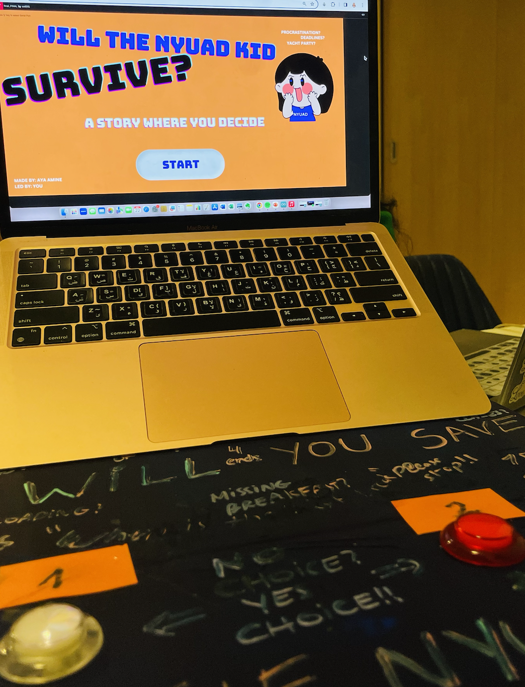
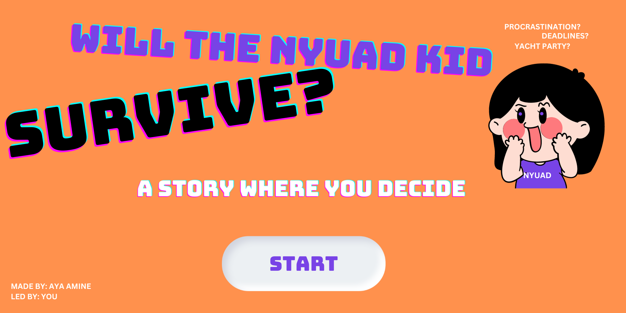
“WILL THE NYUAD KID SURVIVE”, an interactive story where YOU decide!!
It’s complicated to be a university student, but even more to be in your twenties. But… when you’re both.. IT’S FIRE! Do I want to be this or that? Do I want to do this or that? Do I even have time to do that? TWENTIES CRISIS LADIES AND GENTLEMAN.
When finals week hits, I start wondering if I still exist. It just feels like everything is out of control. When I realized that my original idea for the final project can’t be further implemented and I was stuck with nothing, I felt that I lost control. Then, the concept for this project came last minute. I thought of an experience where the users may relate and make their own choices: an interactive story that narrates a typical day in the life of a student. A total of 10 scenes with different short scripts; each scene prompts the user to choose one choice out of two. Each choice leads to a different ending, so the story is not linear.
INSPIRATION:
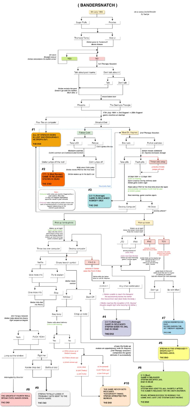
Few months ago, I became really fond of Interactive movies. Interactive movies prompt the viewer to choose the path of the movie and affect the ending. I love the fact that the viewer gets to be a part of the movie itself, especially because viewers base their choices on personal opinions/beliefs. What I admire more about interactive movies is the flexibility of the story. Just look at the story flowchart of “Bandersnatch” one of the interactive movies I watched and loved recently. 8 different endings!
Going back to my project, I thought of making a mini version of this, but the twist here is the physical computing part (+the NYUAD theme). The user keeps up with the story while making choices using a physical platform; constituted of 3 push buttons; a re/play button, a button to choose choice 1 and button to choose choice 2. Before I move to the implementation part, I will share the synopsis, flowchart and sample scenes from my story.
Synopsis: A day in the life of a sleep deprived university student in their finals week. The story unfolds at 6am when the alarm goes on. From waking up or snoozing the alarm to the last setting of the story, YOU have to make decisions that you think are the best for your character’s development. Keep in mind that some choices are fatal, you will cause the story to end!! Make sure to restart and try all different flows of the story and please, make good choices..
Flowchart:
As you can see, the story is pretty short since it’s a mashup (but also because of time constraints!). I counted 10 scenes with 4 endings.
Sample scenes:
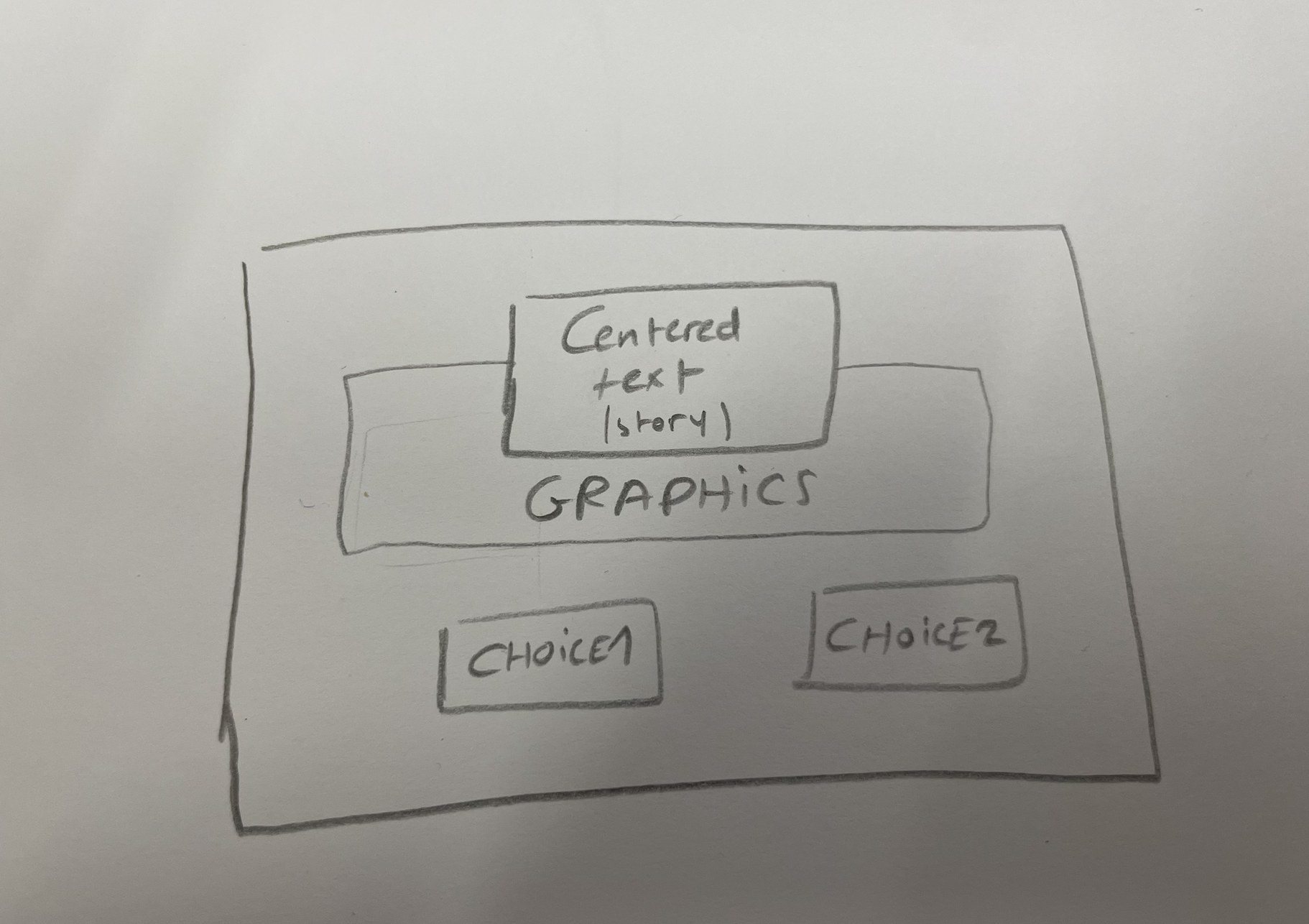
I tried to invest more time in the design aspect of this experience unlike my previous projects, because due to the nature of the project, I knew it would be a hassle for users to read a lot of distorted text, or keep up with dull graphics and color palettes. All 10 scenes have the same layout and elements: short descriptive, centered and readable text, graphics and of course sound for more immersion. Now let’s be more technical:
IMPLEMENTATION:
CIRCUIT:
A simple circuit made of 2 arcade buttons + one regular switch allowing an easy and straightforward user interaction, here’s the schematic:
2. CODE:
Full commented p5js code + Arduino code commented out
3. INTERACTION DESIGN:
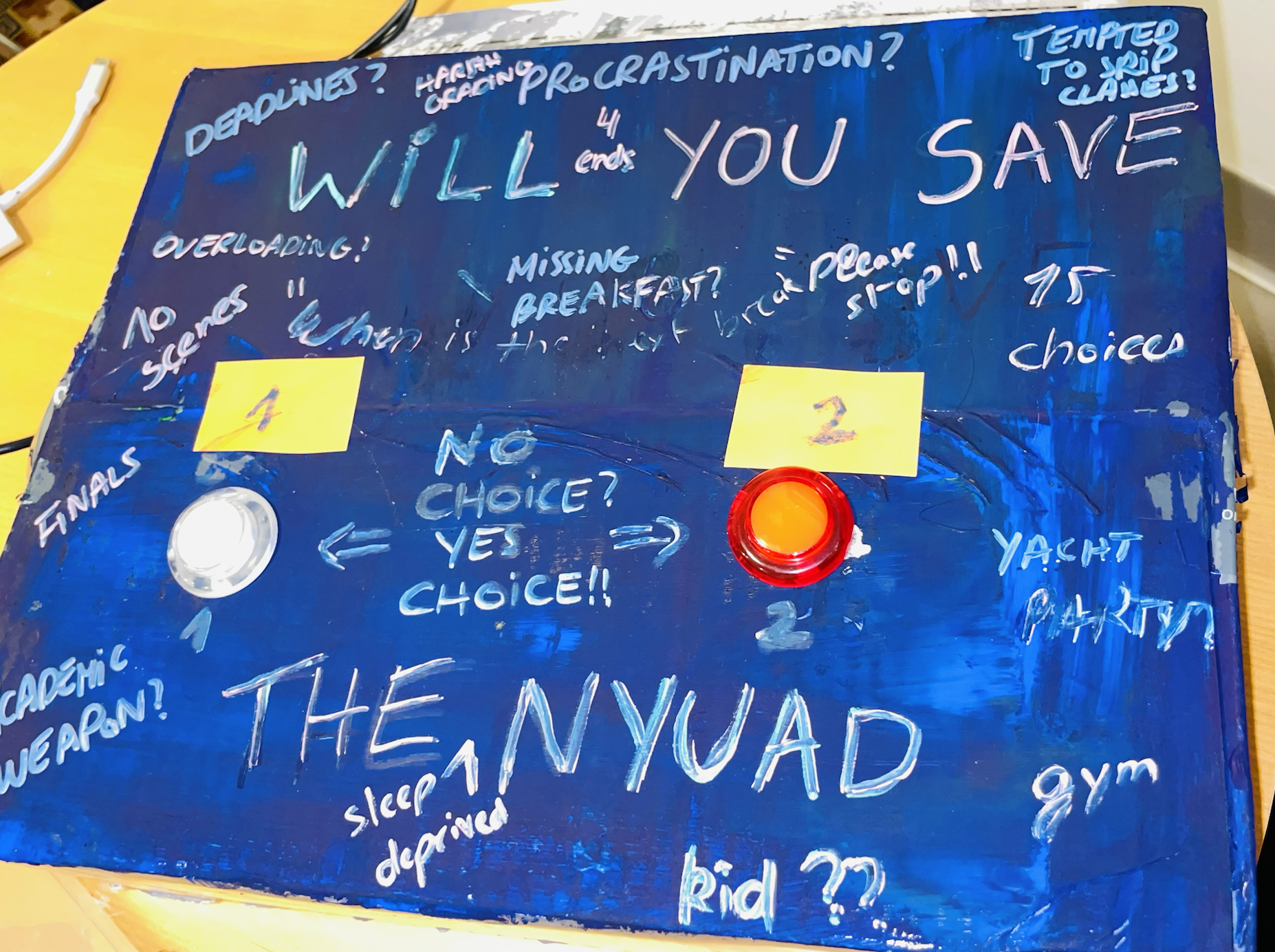
I designed a not-so-fancy box out of cardboard with the two choices button as the pictures show. The circuit is under it and it also contains the third switch (small switch so way to add it on the box). I was planning to use 3 arcade buttons but ended up with only two available at the time of implementation, which was a bit inconvenient.
The writings on the box are inspired from Graffiti but also align with the vision I had in mind. Messy and blurred words just like my brain during this finals week, expressing a lot of thoughts. The headline is “WILL YOU SAVE THE NYUAD KID? – NO CHOICE? YES CHOICE! CHOOSE 1 -2”
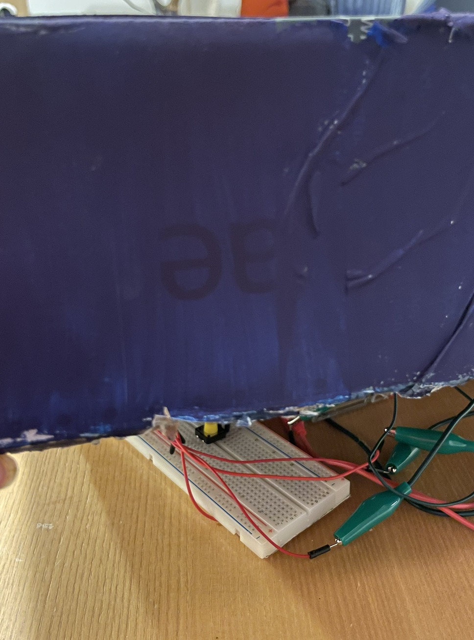
UNDER THE BOX (regular switch showing):
CHALLENGES:
I had a lot of challenges with this project. First of all, I lost my previous project few days before the showcase which means I only started this one a few days before the showcase. I unfortunately ended up not presenting it for other reasons as well. Hence, I would say my main issue in this project was time as I did not have time to do everything I had in mind. When looking at the outcome, I wished I chose this idea from the beginning and took time to implement it well with a better storyline, more interactivity and a more challenging physical computing. I would have also gotten great suggestions from my professor and peers on how to make this idea better. Yet, I’m glad for the lessons I learned along the implementation of this project, many of them are life lessons (ie. better time management!)
IMPROVEMENTS:
-A better storyline: If I had more time, I would have written a more eventful storyline, probably with more scenes, choices and endings. It would have made the story more engaging and longer (I calculated the time my users took trying this project and it was about >10mins, which is pretty quick for such an experience).
-More interactivity: I thought a lot about implementing few games between the scenes (find the place, puzzle games, quiz..) but I didn’t implement any because of rushing. Another better version of this project would have games and stuff to engage the users more.
-A better use of hardware: I went with buttons (which were straightforward to implement) again because of the time I had, but I know there are other ways that could have made my physical computing part more challenging and interesting (ie. I thought of using the potentiometer to turn the pages of the story or a similar effect, but I had no idea how to implement this..).
ALL IN ALL, I CAN’T BELIEVE THIS IS THE END OF AN AMAZING ERA. I’M VERY PROUD OF THE WORK I PUT IN THIS PROJECT DESPITE THE SETBACKS, JUST LIKE ALL MY PREVIOUS PROJECTS. WE’VE COME A LONG WAY!!
Thank you to Professor Shiloh for being the greatest support, to my friend Nourhane for testing all my projects, to my classmates for always suggesting great ideas for all my other projects.
REFERENCES:
Checked this blog to figure out the arcade buttons; http://forum.arcadecontrols.com/index.php?topic=154794.0
Not very helpful but found this project interesting (also had arcade buttons): https://www.youtube.com/watch?v=DYVHlhglcaI
All graphics used were made with Canva, and sound effects/music files are royalty-free except:
The Weeknd – Blinding Lights; https://youtu.be/fHI8X4OXluQ?si=rCqanU4iM-RCnWno
The article delves into the relationship between design and disability, emphasizing the critical importance of well-crafted design in creating accessible and inclusive goods. I agree with the article’s concept that good design is essential in serving the different demands of those with disabilities, both aesthetically and functionally. The emulation of the iPod’s iconic simplicity and functionality is a powerful tribute to the success that can be achieved via smart design. The Muji CD player and Leckey Woosh chair emphasize minimalism as a key design principle. I agree with the emphasis on addressing varied demands while ensuring products remain intuitive and user-friendly as the piece navigates the delicate balance between simplicity and universality.
In reviewing the article, I found resonance in the plea for a more inclusive and sensitive design approach that incorporates cognitive accessibility and cultural inclusion. The inclusion of designers from various backgrounds and experiences, particularly in the field of disability-related goods, resonates with my belief in the value of varied perspectives in the creative process. The end of the post, advocating for the importance of simplicity and user-centered design in developing true inclusivity and accessibility, resonates strongly with my own beliefs.
Lastly,the various tensions explored between fashion and caution in designing for people with disabilities highlight the complexities of this interaction. Finding a healthy balance between showing good representations of disability and avoiding the accidental implication of shame, in my opinion, is critical. The study of the difficult balance required between fashion and invisibility in the essay aligns with my conviction that products should promote positive representations of disabilities without resorting to concealment. In summary, these tensions highlight the complicated interplay between making items that are accessible while also upholding cultural and aesthetic values, a challenge that I eagerly accept.
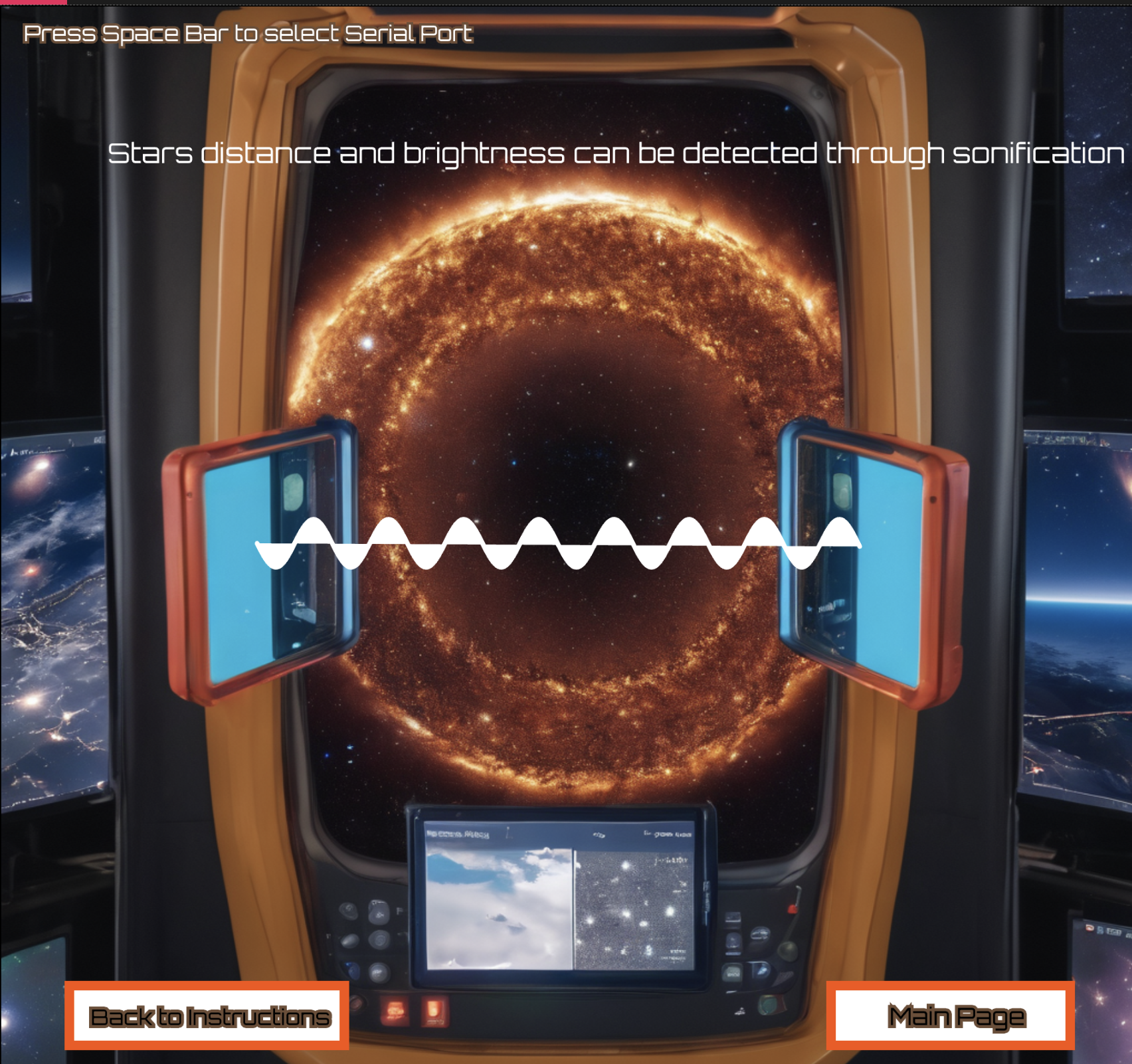
I drew inspiration for my final project from the concept of sonification within the realm of astronomy, a fascination that emerged during my exploration in an astronomy and cosmology course. Despite deviating from my initial plan to incorporate specific data, the overarching aim of the project was to offer an engaging educational experience, shedding light on the absence of sounds in outer space. Alternatively, one might say it aimed to introduce users to sonification, a process wherein astronomical data is translated into audible sounds, fostering a profound connection with the cosmos. Sonification proves particularly valuable when dealing with extensive datasets that may be challenging to visualize or analyze. Through sound, individuals can more easily perceive alterations in waves, frequencies, and patterns.
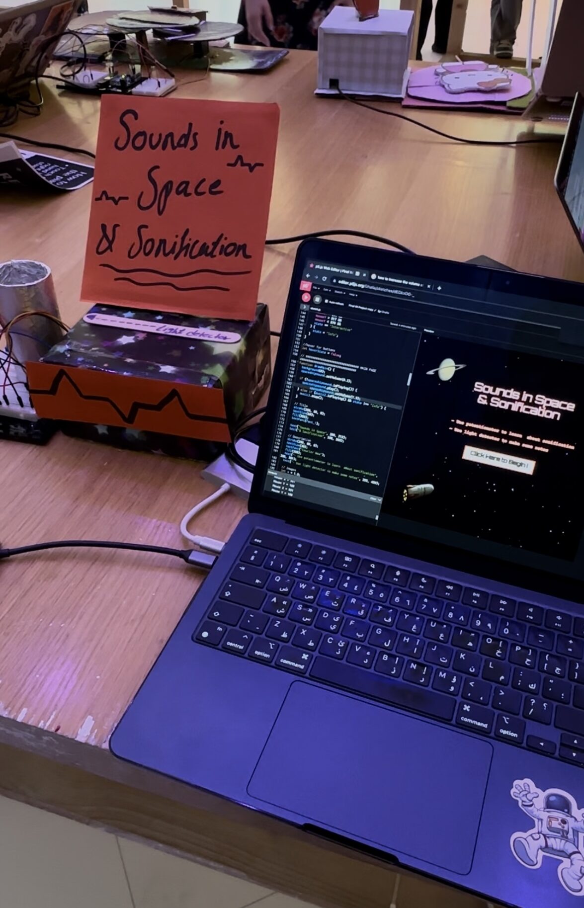
How it Works:
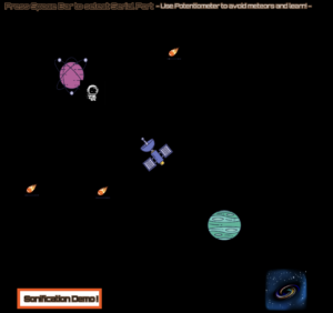
The functionality of this educational game commences on the main page, featuring instructions on utilizing the potentiometer and light sensor. Users initiate the game by clicking the start button. The first page serves as an informational hub, prompting users to employ the potentiometer to maneuver a miniature astronaut towards various celestial objects (planets, satellites, etc.). At each element encountered, informative text is displayed, delving into topics such as sounds in space, how media portrays such sounds, the concept of sonification, and two practical examples of its application. The unique challenge lies in reading this information while navigating the astronaut through the cosmos and avoiding incoming meteors. The subsequent section of the educational game offers a hands-on demonstration of sonification. Users can use the palm of their hands and a flashlight which can be detected by a light sensor. This detection is then translated into piano notes, with low, moderate, and high pitches corresponding to varying levels of brightness. Users can both hear the resulting musical notes and observe a wave visualization representing the light frequency, facilitating a comprehensive understanding of the process.
Communication between Arduino and P5js :
Most of the communication between the hardware and software involved messages from arduino sending to p5js where the output is. These messages are values from the potentiometer and the light sensor, hence the values are splitted by a comma. The serial connection is implemented using the serial port library.
//Arduino Code final IM project

//  Example of bidirectional serial communication

// Inputs:
// - A0 - sensor connected as voltage divider (e.g. potentiometer or light sensor)
// - A1 - sensor connected as voltage divider
//
// Outputs:
// p5js sound


void setup() {
  // Start serial communication so we can send data
  // over the USB connection to our p5js sketch
  Serial.begin(9600);

  // We'll use the builtin LED as a status output.
  // We can't use the serial monitor since the serial connection is
  // used to communicate to p5js and only one application on the computer
  // can use a serial port at once.
  pinMode(LED_BUILTIN, OUTPUT);

  // start the handshake
  while (Serial.available() <= 0) {
    digitalWrite(LED_BUILTIN, HIGH); // on/blink while waiting for serial data
    Serial.println("0,0"); // send a starting message
    delay(300);            // wait 1/3 second
    digitalWrite(LED_BUILTIN, LOW);
    delay(50);
  }
}

void loop() {
  // wait for data from p5 before doing something
  while (Serial.available()) {
    digitalWrite(LED_BUILTIN, HIGH); // led on while receiving data
    int left = Serial.parseInt();
    int right = Serial.parseInt();
    if (Serial.read() == '\n') {
      int sensor = analogRead(A0);
      delay(50);
      int sensor2 = analogRead(A1);
      delay(5);
      Serial.print(sensor);
      Serial.print(',');
      Serial.println(sensor2);
    }
  }
   digitalWrite(LED_BUILTIN, LOW);
}
P5js Code :
For this assignment, I endeavored to introduce a novel approach for navigating between pages, distinct from the method employed in my midterm project. Within my draw function, I utilized the concept of state to showcase various pages and their respective elements whenever a mouse-click event occurred at specific coordinates. Drawing inspiration from Fausto Fang’s code, I sought to understand and implement this technique. The primary innovations incorporated into my final project revolved around the integration of hardware input and laptop-generated output. Specifically, I harnessed data from a light sensor and a potentiometer, utilizing specific ranges to orchestrate the movement of a miniature astronaut and the production of musical notes as a form of sonification.
Reflection & improvements:
I addressed neglected or previously inefficiently implemented elements, such as ensuring buttons visually stand out when the mouse hovers over them. Furthermore, I implemented features like displaying a warning when meteors collide with the mini astronaut (controlled by the potentiometer) and triggering the playback of three distinct sounds on each page, including an explosion audio resulting from the meteor clashing with the astronaut. I was particularly proud of the aesthetic and the idea itself. I’m very passionate about science and astronomy, and I’m always looking for ways to integrate it in my technological field, and creating an educational game was one of the best ideas.
There is always room for improvement. First of all, if I had the chance, I would’ve used the panel mount pot potentiometer instead of the trim pot, simply because it would be easier for users to handle it. I would display the directions of the game differently by explaining how the potentiometer works and where to use it exactly because not everyone knows how it works. When it comes to the hardware, I think I should’ve placed more effort into creating the concept of sonification by using a flash light attached to a star structure or something that resembles the concept more. Additionally , it takes it a minute to load everything and I haven’t been able to figure out a way around it.
User Experiences:
When users attempted to play the game, some read the directions and understood where to start and what to expect as results, while others were either confused by the functionality of the potentiometer, and some didn’t know what the controls are and how to make the game work. Although I had some instructions, I think I need to be more precise about what the potentiometer does, how it’s supposed to be rotated, and when exactly they can use the light sensor.
Note: I added some background sound that is originally in the project but it was too loud for it to be heard in the recording.
Overall Experience:
Overall, the experience is good enough and easy to work with. However, I felt the need to explain how to use the potentiometer often and when to use the light sensor. I had to explain why is sonification used in the field of astronomy, so maybe that’s something I could add in the project itself. One can understand how it works through the instructions but they can be improved in terms of how apparent and visible they are to the users and giving more details to how the sensors work along with p5js.
In this week’s assignments, we were tasked with figuring out three different exercises to understand and practice serial communication between Arduino and P5js.
EXERCISE 1:
In this exercise we have to make an eclipse move across the p5js sketch using anything on the Arduino. For this we decided to use a potentiometer and an eclipse that gradually changes color along with it’s background.
Code:
/* Week 11.2 bidi serial example
 * Originally by Aaron Sherwood
 * Modified by Mangtronix
 *
 * Add this library to Sketch files
 *  https://github.com/mangtronix/IntroductionToInteractiveMedia/blob/master/code/p5.web-serial.js files
 *
 * You must include this line in your index.html (in Sketch Files) to load the
 * web-serial library
 *
 *     <script src="p5.web-serial.js"></script>
 *
 * Arduino code:
 * https://github.com/mangtronix/IntroductionToInteractiveMedia/blob/master/code/Week11Serial.ino
 */


let rVal = 0;
let alpha = 255;
let left = 0; // True (1) if mouse is being clicked on left side of screen
let right = 0; // True (1) if mouse is being clicked on right side of screen

function setup() {
  createCanvas(640, 480);
  textSize(18);
}

function draw() {
  // one value from Arduino controls the background's red color
  background(map(rVal, 0, 1023, 0, 255), 255, 255);
let ellipseX = map(rVal, 0, 1023, 0, width);
  ellipse(ellipseX, height / 2, 50, 50); // The ellipse's Y position is fixed at the center

  // the other value controls the text's transparency value
  fill(255, 0, 255, map(alpha, 0, 1023, 0, 255));

  if (!serialActive) {
    text("Press Space Bar to select Serial Port", 20, 30);
  } else {
    text("Connected", 20, 30);

  }


  // click on one side of the screen, one LED will light up
  // click on the other side, the other LED will light up
  if (mouseIsPressed) {
    if (mouseX <= width / 2) {
      left = 1;
    } else {
      right = 1;
    }
  } else {
    left = right = 0;
  }
}

function keyPressed() {
  if (key == " ") {
    // important to have in order to start the serial connection!!
    setUpSerial();
  }
}

// This function will be called by the web-serial library
// with each new *line* of data. The serial library reads
// the data until the newline and then gives it to us through
// this callback function
function readSerial(data) {
  ////////////////////////////////////
  //READ FROM ARDUINO HERE
  ////////////////////////////////////

  if (data != null) {
    // make sure there is actually a message
    // split the message
    let fromArduino = split(trim(data), ",");
    // if the right length, then proceed
    if (fromArduino.length == 2) {
      // only store values here
      // do everything with those values in the main draw loop

      // We take the string we get from Arduino and explicitly
      // convert it to a number by using int()
      // e.g. "103" becomes 103
      rVal = int(fromArduino[0]);
      alpha = int(fromArduino[1]);
    }

    //////////////////////////////////
    //SEND TO ARDUINO HERE (handshake)
    //////////////////////////////////
    let sendToArduino = left + "," + right + "\n";
    writeSerial(sendToArduino);
  }
}

//Arduino Code
/*
// Week 11.2 Example of bidirectional serial communication

// Inputs:
// - A0 - sensor connected as voltage divider (e.g. potentiometer or light sensor)
// - A1 - sensor connected as voltage divider
//
// Outputs:
// - 2 - LED
// - 5 - LED

int leftLedPin = 2;
int rightLedPin = 5;

void setup() {
  // Start serial communication so we can send data
  // over the USB connection to our p5js sketch
  Serial.begin(9600);

  // We'll use the builtin LED as a status output.
  // We can't use the serial monitor since the serial connection is
  // used to communicate to p5js and only one application on the computer
  // can use a serial port at once.
  pinMode(LED_BUILTIN, OUTPUT);

  // Outputs on these pins
  pinMode(leftLedPin, OUTPUT);
  pinMode(rightLedPin, OUTPUT);

  // Blink them so we can check the wiring
  digitalWrite(leftLedPin, HIGH);
  digitalWrite(rightLedPin, HIGH);
  delay(200);
  digitalWrite(leftLedPin, LOW);
  digitalWrite(rightLedPin, LOW);


  // start the handshake
  while (Serial.available() <= 0) {
    digitalWrite(LED_BUILTIN, HIGH); // on/blink while waiting for serial data
    Serial.println("0,0"); // send a starting message
    delay(300);            // wait 1/3 second
    digitalWrite(LED_BUILTIN, LOW);
    delay(50);
  }
}

void loop() {
  // wait for data from p5 before doing something
  while (Serial.available()) {
    digitalWrite(LED_BUILTIN, HIGH); // led on while receiving data

    int left = Serial.parseInt();
    int right = Serial.parseInt();
    if (Serial.read() == '\n') {
      digitalWrite(leftLedPin, left);
      digitalWrite(rightLedPin, right);
      int sensor = analogRead(A0);
      delay(5);
      int sensor2 = analogRead(A1);
      delay(5);
      Serial.print(sensor);
      Serial.print(',');
      Serial.println(sensor2);
    }
  }
  digitalWrite(LED_BUILTIN, LOW);
}
*/
P5* Sketch: Video:
EXERCISE 2:
For this exercise we were tasked with making an LED change brightness based on a p5js sketch, which we decided to make more interesting by taking inspiration from the sun and making a p5 sketch look like a sky. The latter has moving clouds and a sun that changes based on the brightness which is controlled by the keyboard “up” and “down” keys which also control the LED brightness.
Code:
let brightness=0;
let cloud1X = 100;
let cloud2X = 40;
let cloud3X = 200;

function setup() {
  createCanvas(1000, 480);
  textSize(18);
}


function draw() {
  noStroke();
  background(135, 206, 235);
  fill(0);
  drawCloud(cloud1X, 60); // Cloud on the right of the sun
  drawCloud(cloud2X, 100); // Cloud below the sun
  drawCloud(cloud3X, 350); // Cloud at the bottom

  //Moves the clouds
  cloud1X += 1;
  cloud2X += 1;
  cloud3X += 1;
  // Loop the clouds once they move off screen
  if (cloud1X > width + 30) {
    cloud1X = -60;
  }
  if (cloud2X > width + 30) {
    cloud2X = -60;
  }
  if (cloud3X > width + 30) {
    cloud3X = -60;
  }


  if (!serialActive) {
    text("Press Space Bar to select Serial Port", 20, 30);
  } else {
    text("Connected", 20, 30);
  }
  fill(255,255,0,brightness)
  circle(width/2-150,height/2-30, 100)
  fill(0)
  text("WATCH THE SUN LIGHT UP: "+str(brightness),width/2-50,height/2)
  text("UP to make the brightness higher, DOWN to make brightness dimmer ",width/2-220,height/2+50)

  if (keyIsPressed) {
    if (keyCode==UP_ARROW) {
      if (brightness<255){
        brightness+=5;
      }
    } else if (keyCode==DOWN_ARROW) {
      if (brightness>0){
        brightness-=5;
      }

    }
  }
}


function drawCloud(x, y) {
  fill(255);

  // Group of ellipses to form a cloud shape
  ellipse(x, y, 30, 30);
  ellipse(x + 20, y, 30, 30);
  ellipse(x - 20, y, 30, 30);
  ellipse(x - 20, y, 30, 30);
  ellipse(x + 10, y + 15, 30, 30);
  ellipse(x - 10, y + 15, 30, 30);
}
function keyPressed() {
  if (key == " ") {
    // important to have in order to start the serial connection!!
    setUpSerial();
  }
}

function readSerial(data) {
  if (data != null) {
    writeSerial(brightness+"\n");
  }
}
//ARDUINO
//int LedPin = 9;

//void setup() {
  // Start serial communication so we can send data
  // over the USB connection to our p5js sketch
  //Serial.begin(9600);

  // We'll use the builtin LED as a status output..
  //pinMode(LED_BUILTIN, OUTPUT);

  // Outputs on this pin
  //pinMode(LedPin, OUTPUT);

  // Blink them so we can check the wiring
 // digitalWrite(LedPin, HIGH);
 // delay(200);
 // digitalWrite(LedPin, LOW);

  // start the handshake
 //// while (Serial.available() <= 0) {
 //   digitalWrite(LED_BUILTIN, HIGH); // on/blink while waiting for serial data
  //  Serial.println("0"); // send a starting message
  //  delay(300);            // wait 1/3 second
  //  digitalWrite(LED_BUILTIN, LOW);
  //  delay(50);
////  }
//}

//void loop() {
  // wait for data from p5 before doing something
//  while (Serial.available()) {
 //   Serial.println("0");
 //   digitalWrite(LED_BUILTIN, HIGH); // led on while receiving data

 //   int brightness = Serial.parseInt();
 //   if (Serial.read() == '\n') {
  //    analogWrite(LedPin, brightness);
 //   }
 // }
 // digitalWrite(LED_BUILTIN, LOW);
//}
P5* sketch:
Video:
EXERCISE 3:
This exercise comes in two parts, part one is creating a circuit that can blink an LED every time that the ball bounces on the p5 sketch and the second part is making a circuit that controls the wind on the game and moves the ball depending on it and as a general theme and personal touch we choose to use a soccer ball and green background.
Part 1 and 2 code:
let velocity;
let gravity;
let posit5
let acceleration;
let wind;
let drag = 0.99;
let mass = 50;
let LED=0;
let wind_speed=0;
let ball;

function preload(){
  ball = loadImage('ball.png');
}

function setup() {
  createCanvas(640, 360);
  noFill();
  position = createVector(width/2, 0);
  velocity = createVector(0,0);
  acceleration = createVector(0,0);
  gravity = createVector(0, 0.5*mass);
  wind = createVector(0,0);
}

function draw() {
  background (34, 139, 34 );
  fill(0)
  if (!serialActive) {
    text("Press , RIGHT key to select Serial Port", 20, 30);
  } else {
    text("Connected", 20, 30);
  }
  applyForce(wind);
  applyForce(gravity);
  velocity.add(acceleration);
  velocity.mult(drag);
  position.add(velocity);
  acceleration.mult(0);
  fill(205,104,219);
  imageMode(CENTER); // Ensures the image is centered on the position
  image(ball, position.x, position.y, mass, mass); // Draw the image
  if (position.y > height-mass/2) {
      velocity.y *= -0.9;  // A little dampening when hitting the bottom
      position.y = height-mass/2;
    }

  if (position.y==height-mass/2){
    LED=1
  }
  else{
    LED=0
  }

  if (position.x>=width || position.x<=0){
    position.x=width/2
  }


}

function applyForce(force){
  // Newton's 2nd law: F = M * A
  // or A = F / M
  let f = p5.Vector.div(force, mass);
  acceleration.add(f);
}

function keyPressed(){
  if (key==' '){

    mass=random(15,80);
    position.y=-mass;
    velocity.mult(0);
  }
  if (keyCode==RIGHT_ARROW){
    setUpSerial();
  }
}

function readSerial(data) {
  ////////////////////////////////////
  //READ FROM ARDUINO HERE
  ////////////////////////////////////

  if (data != null) {
    let fromArduino = trim(data);
    distance= int(fromArduino);
    if (distance>10){
      wind.x=2
    }
    else{
      wind.x=-2
    }

    let sendToArduino = LED+"\n";
    writeSerial(sendToArduino);
  }
}

//Arduino
// int LedPin = 9;
// int trigPin = 8;
// int echoPin = 10;
// long duration;
// int distance;

// void setup() {
//   // Start serial communication so we can send data
//   // over the USB connection to our p5js sketch
//   pinMode(trigPin, OUTPUT);
//   pinMode(echoPin, INPUT);
//   Serial.begin(9600);
//   pinMode(LED_BUILTIN, OUTPUT);
//   // Outputs on these pins
//   pinMode(LedPin, OUTPUT);
//   // Blink them so we can check the wiring
//   digitalWrite(LedPin, HIGH);
//   delay(200);
//   digitalWrite(LedPin, LOW);
//   // start the handshake
//   while (Serial.available() <= 0) {
//     digitalWrite(LED_BUILTIN, HIGH); // on/blink while waiting for serial data
//     Serial.println("0,0"); // send a starting message
//     delay(300);            // wait 1/3 second
//     digitalWrite(LED_BUILTIN, LOW);
//     delay(50);
//   }
// }
// void loop() {
//   // wait for data from p5 before doing something
//   while (Serial.available()) {
//     digitalWrite(LED_BUILTIN, HIGH); // led on while receiving data
//     int LED = Serial.parseInt();
//     if (Serial.read() == '\n') {
//       digitalWrite(LedPin, LED);
//       digitalWrite(trigPin, LOW);
//       delayMicroseconds(2);
//       digitalWrite(trigPin, HIGH);
//       delayMicroseconds(10);
//       digitalWrite(trigPin, LOW);
//       // Reads the echoPin, returns the sound wave travel time in microseconds
//       duration = pulseIn(echoPin, HIGH);
//       // Calculating the distance
//       distance = duration * 0.034 / 2;
//       Serial.println(distance);
//     }
//   }
//   digitalWrite(LED_BUILTIN, LOW);
// }
Jump Jump Revolution game controlled by the DDR physical platform did not work unfortunately. Two pressure sensors were lost (& all the labs in the university decided to run out of them :(( ) resulting in the whole project being canceled, while both the game and the physical platform were ready. As a result, I had to do a last minute change of plans for my final project idea.
The new concept is the following: “WILL THE NYUAD KID SURVIVE”, an interactive story where YOU decide!!
INSPIRATION:
I had the idea to make this interactive story in the middle of the pressure of finals week as a result of idea changing. Hence, my synopsis was very much influenced by what I wished I could do/have in this final week. What if I could snooze my alarm? skip that exam? go to a party? WHAT IF I CAN JUST DITCH THE PRESSURE 🙁 I know many of my fellow peers feel the same, hence what if we could actually make crazy choices without worrying about the consequences? “WILL THE NYUAD SURVIVE?- short for WILL THE NYUAD SURVIVE THE FINALS WEEK?” is an interactive story where the user is presented with two choices in different scenarios. The user has to make a decision each time that will affect the ending of the story. N.B: The decision may be fatal => causing the story to end.
Of course, there are many outcomes and many endings to the story because each decision is followed by a different flow of events. I made a tree of events explaining the flow of events that I will share in the final project documentation with the full explanation (just in case I end up changing something in the story).
UI design:
=> Aesthetic graphics corresponding to each scenario.
=> Text to narrate the story
=> Sound to make the experience immersive.
INTERACTION DESIGN:
I chose to make a DIY TV controller with buttons. The TV controller will have 3 buttons each controlling something in the sketch: a button for start/restart to not physically start the p5 sketch each time, a button for pausing the sketch, 2 buttons corresponding to each of the two choices.
The next post will be my final project documentation, documenting my final project from A to Z, with some user testing!
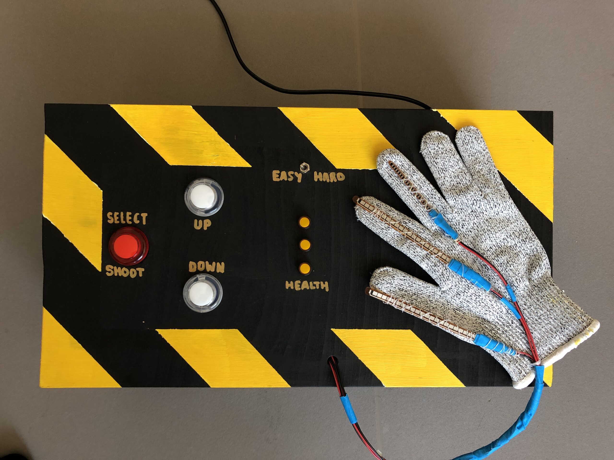
I decided to implement my idea of creating a unique controller for a video game, which in my case, was gesture control with a glove. I had decided to continue with the initial design; however, I decided to add an additional switch to change between simple button controls and using the glove to control the game. The game was a mash-up of Plants vs. Zombies and Space Invaders. I drew all the graphics for the game myself, and the game would be a high-score-based experience where each player can try to beat the previously set high score. Additionally, the enemies in the game spawn infinitely, and the difficulty increases with each wave of incoming enemies. The difficulty is dependent on the time that has passed since the start of the game and is measured by the speed at which the enemies come at you. Additionally, the game is fully controllable through the arcade-styled “controller box,” which has “SELECT, UP, DOWN” buttons and a toggle switch to change between “HARD” (glove controlling) and “EASY” (button control). Overall, I found the design quite intuitive, as did many others. Additionally, while working on the code, I added a feature to control the game through keyboard inputs, which can be activated by uncommenting the specified code segments.
User-Testing + Images & Videos
I had numerous friends try and use the project I have created, and the results were highly positive. The design was intuitive, and after just one or two tries, the testers got the hang of how the box and glove functioned. Overall, I think a big issue was that at the show, people did not spend much attention reading the instructions, which resulted in me having to restate what was written there verbally; in a more focused environment, I am sure this project would be very understandable and easy to use. It is, however, challenging to get used to controlling the player with the glove, and thus, it was called the HARD mode. Additionally, due to the issue of not being able to reuse the red button for switching between screens, I had to add some unique features for it to be better understood. In the instructions, I explicitly mention that you must first press the up and then start buttons, and after the game is over, the up and down buttons start blinking, indicating that you must press them together to restart the game. I will surely try to structure the code a bit differently whenever similar projects come up in the future.
Implementation
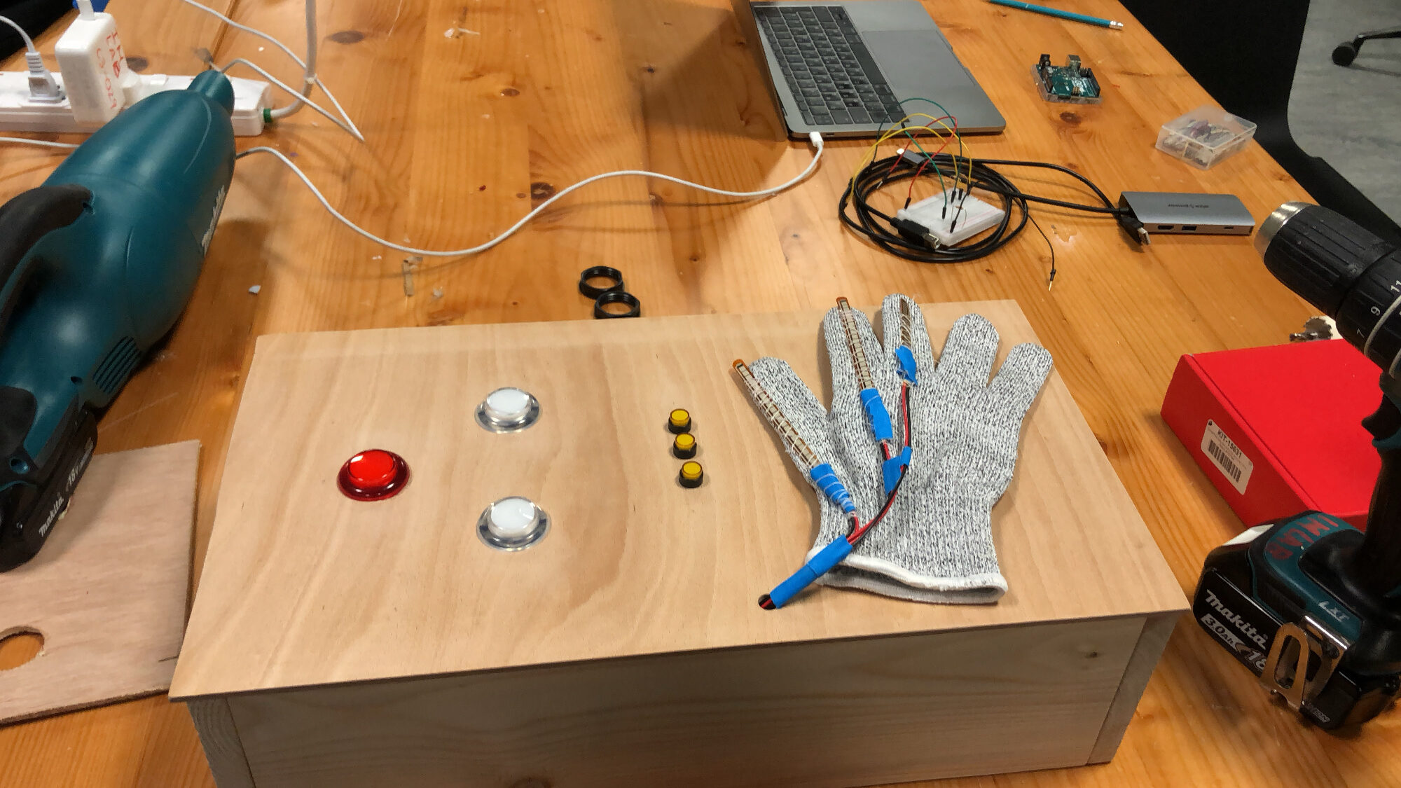
Interaction + Physical Design: My main intention with the design of this project was to make it reminiscent of the old-school arcade-style games, from the big light-up buttons, LEDs, and switches to the pixelated game characters and animations. I wanted to create a satisfying and nostalgic experience for the players of the game of a time when they had been to an arcade as a child. As I later found out, many people in the community here have not had these experiences before; therefore, it was also a new experience for them. However, the implementation of the glove provided a futuristic and high-tech twist to the old-school-styled project. This also interested many because who wouldn’t want to try playing a simple game with controls that are so different than what we are used to? Overall, I spent many hours designing, painting, and ensuring the physical structure of the box was well-thought-out and intuitive. A few images of the construction can be seen below.
Arduino
Surprisingly, the Arduino implementation of my project was much simpler than I had expected. The entire Arduino code is shown below:
//flex sensors and their respective fingers/input pins
int thumb = A2;
int index = A1;
int middle = A0;

//thersholds for the flex sensors
int bend = 800;
int thumb_bend = 730;


//inputs for digital switches
int mode_switch = 2; /// left side is 1 right is 0
int health_led1 = 3;
int health_led2 = 4;
int health_led3 = 5;
int white_switch1 = 6;
int white_switch1_led = 7;
int white_switch2 = 8;
int white_switch2_led = 9;
int red_switch = 10;
int red_switch_led = 11;


//variables to send to p5
int move_up = 0;
int move_down = 0;
int shoot = 0;
int still = 0;
int mode = 0;
int white_up = 0;
int white_down = 0;
int red = 0;

// variable from p5
int health = 3;

void get_gesture() {
  int thumb_value = analogRead(thumb);
  int index_value = analogRead(index);
  int middle_value = analogRead(middle);
  if (thumb_value < thumb_bend && index_value > bend && middle_value > bend) { // condition for move up -- every finger bent except thumb
    move_up = 1;
    move_down = 0;
    shoot = 0;
    still = 0;
  } else if (thumb_value > thumb_bend && index_value > bend && middle_value > bend) { // condition for move down -- every finger bent
    move_up = 0;
    move_down = 1;
    shoot = 0;
    still = 0;
  } else if (thumb_value < thumb_bend && index_value < bend && middle_value > bend) { // condition for shooting -- only middle finger bent
    move_up = 0;
    move_down = 0;
    shoot = 1;
    still = 0;
  } else if (thumb_value < thumb_bend && index_value < bend && middle_value < bend) { // condition for no movement -- no fingers bent
    move_up = 0;
    move_down = 0;
    shoot = 0;
    still = 1;
  }
}

void get_switch_values() {  /// this function gets the buttons/switches values (1 or 0), to send to P5
  mode = digitalRead(mode_switch);
  white_up = digitalRead(white_switch1);
  white_down = digitalRead(white_switch2);
  red = digitalRead(red_switch);

  //make the leds with switches turn on with toggle and if pressed.
  if (mode == 1 && health != 0) {
    digitalWrite(white_switch1_led, HIGH);
    digitalWrite(white_switch2_led, HIGH);
    digitalWrite(red_switch_led, HIGH);
  } else if (mode == 0) {
    digitalWrite(white_switch1_led, LOW);
    digitalWrite(white_switch2_led, LOW);
    digitalWrite(red_switch_led, LOW);
    if (white_up == 1) {
      digitalWrite(white_switch1_led, HIGH);
    } else if (white_up == 0) {
      digitalWrite(white_switch1_led, LOW);
    }
    if (white_down == 1) {
      digitalWrite(white_switch2_led, HIGH);
    } else if (white_down == 0) {
      digitalWrite(white_switch2_led, LOW);
    }
    if (red == 1) {
      digitalWrite(red_switch_led, HIGH);
    } else if (red == 0) {
      digitalWrite(red_switch_led, LOW);
    }
  }
}
const long interval = 700;
unsigned long previousMillis = 0;
int ledState = LOW;

void show_health() {  // TURN ON LEDS DEPENDING ON HEALTH, BLINK UP AND DOWN BUTTONS IF DEAD
  if (health == 3) {
    digitalWrite(health_led1, HIGH);
    digitalWrite(health_led2, HIGH);
    digitalWrite(health_led3, HIGH);
  } else if (health == 2) {
    digitalWrite(health_led1, LOW);
    digitalWrite(health_led2, HIGH);
    digitalWrite(health_led3, HIGH);
  } else if (health == 1) {
    digitalWrite(health_led1, LOW);
    digitalWrite(health_led2, LOW);
    digitalWrite(health_led3, HIGH);
  } else if (health <= 0 && mode == 1 || mode == 0) {
    digitalWrite(health_led1, LOW);
    digitalWrite(health_led2, LOW);
    digitalWrite(health_led3, LOW);
    digitalWrite(red_switch_led, LOW);
    unsigned long currentMillis = millis();

    if (currentMillis - previousMillis >= interval) {
    // save the last time you blinked the LED
    previousMillis = currentMillis;

    // if the LED is off turn it on and vice-versa:
    if (ledState == LOW) {
      ledState = HIGH;
    } else {
      ledState = LOW;
    }

    // set the LED with the ledState of the variable:
    digitalWrite(white_switch1_led, ledState);
    digitalWrite(white_switch2_led, ledState);
  }
  }
}

void setup() {
  // Start serial communication so we can send data over the USB connection to our p5js sketch
  Serial.begin(9600);

  //defining the pins
  pinMode(LED_BUILTIN, OUTPUT);
  pinMode(health_led1, OUTPUT);
  pinMode(health_led2, OUTPUT);
  pinMode(health_led3, OUTPUT);
  pinMode(white_switch1, INPUT);
  pinMode(white_switch1_led, OUTPUT);
  pinMode(white_switch2, INPUT);
  pinMode(white_switch2_led, OUTPUT);
  pinMode(red_switch, INPUT);
  pinMode(red_switch_led, OUTPUT);
  pinMode(mode_switch, INPUT);

  //start the handshake
  while (Serial.available() <= 0) { // everything blinks while waiting for serial data from p5
    Serial.println("0"); // send a starting message
    digitalWrite(health_led1, HIGH);
    digitalWrite(health_led2, HIGH);
    digitalWrite(health_led3, HIGH);
    digitalWrite(white_switch1_led, HIGH);
    digitalWrite(white_switch2_led, HIGH);
    digitalWrite(red_switch_led, HIGH);
    delay(300);
    digitalWrite(health_led1, LOW);
    digitalWrite(health_led2, LOW);
    digitalWrite(health_led3, LOW);
    digitalWrite(white_switch1_led, LOW);
    digitalWrite(white_switch2_led, LOW);
    digitalWrite(red_switch_led, LOW);
    delay(300);
  }
}

void loop() {

  // wait for data from p5 before doing something
  while (Serial.available()) {
    digitalWrite(LED_BUILTIN, HIGH); // led on while receiving data
    health = Serial.parseInt();

    if (Serial.read() == '\n') {
        get_gesture();
        get_switch_values();
        show_health();
        delay(1);

        Serial.print(move_up);
        Serial.print(",");
        Serial.print(move_down);
        Serial.print(",");
        Serial.print(shoot);
        Serial.print(",");
        Serial.print(still);
        Serial.print(",");
        Serial.print(mode);
        Serial.print(",");
        Serial.print(white_up);
        Serial.print(",");
        Serial.print(white_down);
        Serial.print(",");
        Serial.print(red);
        Serial.println();
    }
  }
  digitalWrite(LED_BUILTIN, LOW);
}
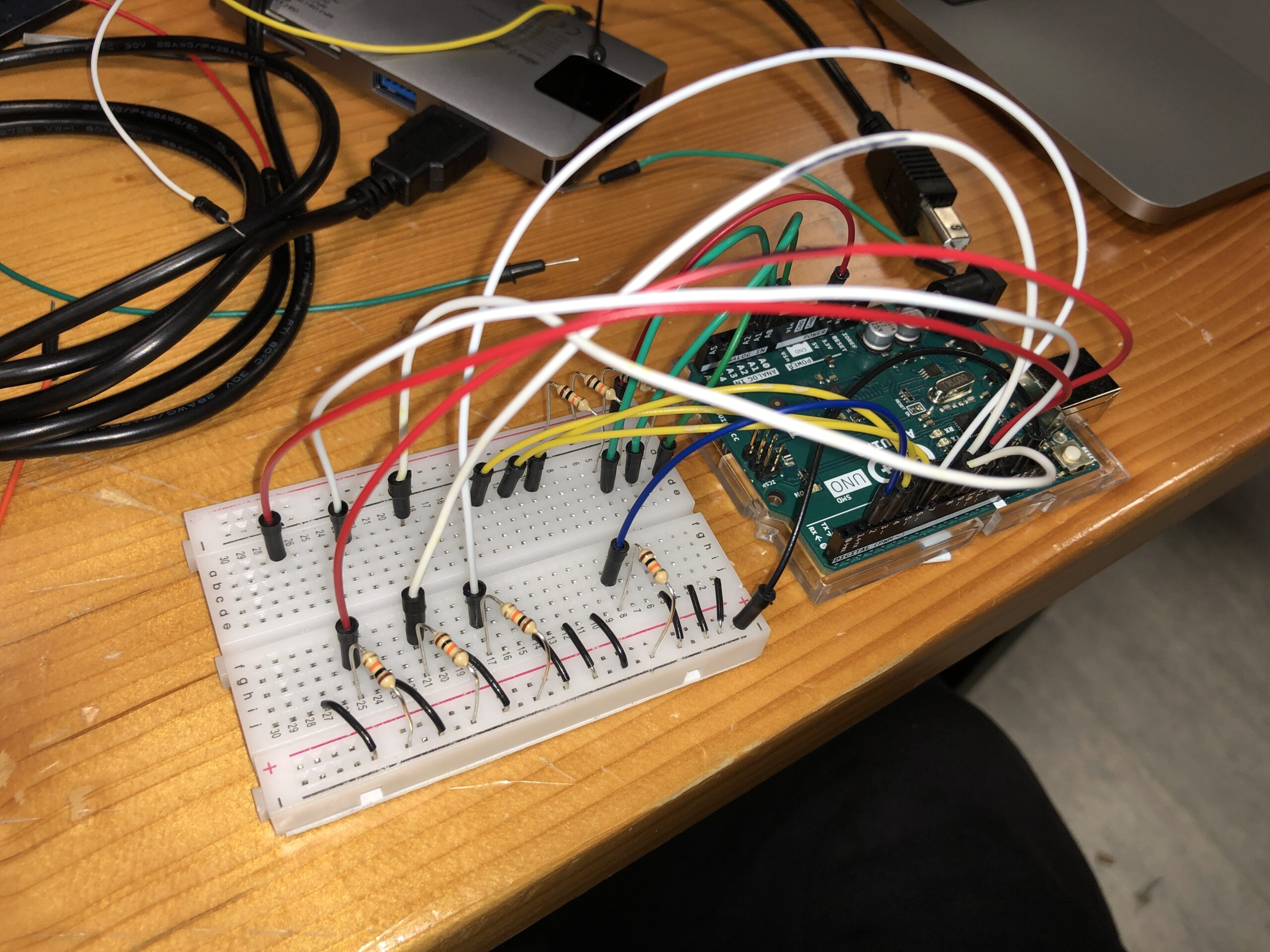
I decided to create functions for each of the actions needed for Arduino to keep the serial communication loop a lot cleaner. Additionally, the gestures are recognized within the Arduino, and then the according values for move_up, down, and so on are sent to P5. Additionally, the circuit design and connections can be seen below:
P5JS
The P5JS code is too long to post here and can be found by following the embedded sketch. The segment below is the one I struggled most with:
check_collision() {
  // check for collisions between bullets and enemies
  for (let b = this.bullets.length - 1; b >= 0; b--) {
    if (this.bullets[b].active) {
      for (let enemy = game.enemies.length - 1; enemy >= 0; enemy--) {
        if (game.enemies[enemy].alive) {
          let enemy_x = game.enemies[enemy].x;
          let enemy_y = game.enemies[enemy].y;
          let bullet_x = this.bullets[b].x;
          let bullet_y = this.bullets[b].y;

          if (dist(bullet_x, bullet_y, enemy_x, enemy_y) < 150) {
            // Bullet hits the enemy
            game.enemies[enemy].explode();
            this.score += 1;
            this.bullets[b].inactive();
          }
        }
      }
    }
  }

  // remove inactive bullets that go beyond the right edge
  this.bullets = this.bullets.filter(
    (bullet) => bullet.active && bullet.x < width
  );

  // check for collisions between enemies and the player
  for (let enemy = game.enemies.length - 1; enemy >= 0; enemy--) {
    if (game.enemies[enemy].alive) {
      let enemy_x = game.enemies[enemy].x;
      let enemy_y = game.enemies[enemy].y;
      let player_x = this.x;
      let player_y = this.y;
      let player_r = this.w / 2;
      let enemy_r = game.enemies[enemy].img_w / 2;

      if (!game.enemies[enemy].collided_with_player) {
        if (dist(player_x, player_y, enemy_x, enemy_y) < player_r + enemy_r) {
          // enemy hits the player
          game.enemies[enemy].explode();
          game.enemies[enemy].collided_with_player = true;
          this.health -= 1;
        }
      }

      // check for enemies reaching the left side of the screen
      if (enemy_x <= 0 && !game.enemies[enemy].collided_with_player) {
        game.enemies[enemy].explode();
        game.enemies[enemy].collided_with_player = true;
        this.health -= 1;
      }
    }
  }
  // remove exploded enemies
  game.enemies = game.enemies.filter((enemy) => enemy.alive);
}
In order to implement functional collision detection between the enemies, bullets, player, and “earth” (left side of the screen), I had to iterate through many lists and add many additional attributes to every class. This method is called in the game class when the game is played. I had to research a new way of removing elements from a list since I ran into MANY issues with the objects being deleted and then another loop trying to access their attributes. Therefore, I decided to look into the “.filter” method in JavaScript to remove certain objects AFTER the loops had finished. The resource I used is linked below. Apart from this, it was also challenging to manage the input of buttons since the Arduino would send 1s and 0s hundreds of times a second. This was resolved by adding a few flags and conditions, which can be found in one of the methods in the game class in the p5 sketch.
Communication – Arduino <-> P5JS
I found the communication between Arduino and P5JS to be very simple and understandable. From the Arduino, I sent 8 values to P5, which can be seen in the Arduino code. I then used these values (1s or 0s) in P5JS to control the character and everything else. Therefore the input from the mouse or keyboard was unnecessary, apart from initially connecting the Arduino to the serial port. P5 sends Arduino the health value of the player, which is then displayed by the LEDs on the mainframe of the box. Unfortunately, the LEDs I used were not as bright as I wanted them to be. However, the function worked well. Overall, I found the communication process quite intuitive and easy to understand.
Challenges & Reflection
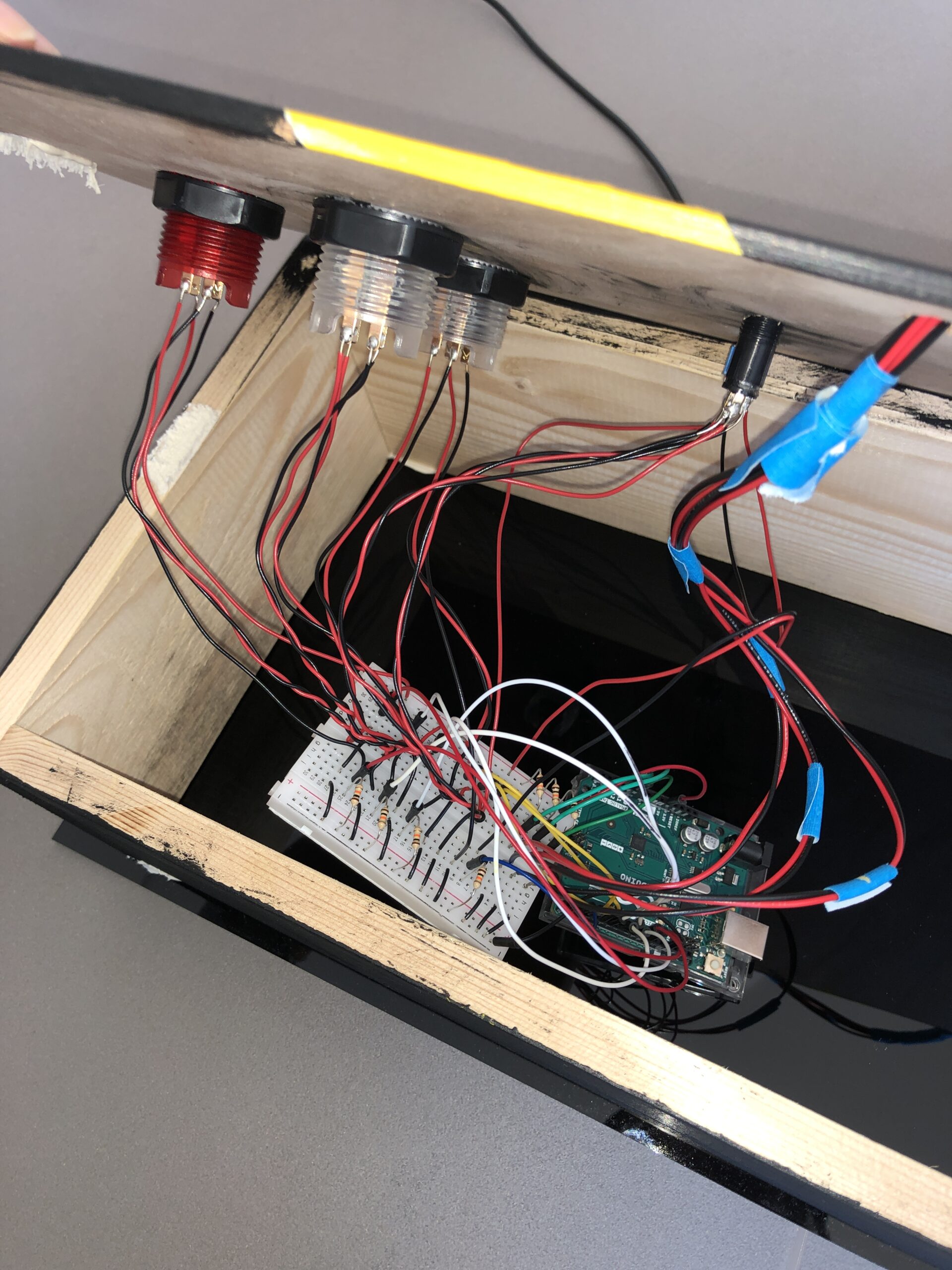
Overall, I found this experience extremely enjoyable since I have never before had a chance to create something that is so advanced (at least for me as a starting interactive media and computer science student). However, there have been many challenges and long nights spent trying to figure out how to make things work. I faced my first challenge when constructing the glove and the enclosure. The flex sensors needed to be able to move and bend; therefore, I had to hand-sow each sensor to the glove instead of gluing them down, which took a lengthy amount of time. Additionally, once I had all the buttons, switches, and LEDs attached to the box, it was highly challenging to insert the wires into the breadboard since there was little space and everything was very tight-knit. Once the box had been constructed, even more challenges arose in P5. The code I had written previously was not working well. Specifically, the collision detection between the bullets and the enemies was not working. It took me over 5 hours of trying to debug the code and test various ways to fix the issue. However, yet again, another issue arose. As I was trying to use one button to change between the screens (states of the game), since the input of the button was read continuously, it was extremely difficult to try to find a way to use one button for different actions on different screens as the readings would be changed right as the state changed. I am sure there is a solution to this; however, as I was running out of time, I had to use an alternative and different buttons for switching between screens. Ultimately, despite the many challenges and difficulties that I have faced, I enjoyed the process and am particularly proud of making the game fully functional and using the glove as an input for controls. I am excited to pursue similar projects in the future. On a side note, I wish I had more time to implement some extra features to my project. For instance, I would have liked to add extra buttons for other features, such as power-ups or a separate restart/start button, and so on. The possibilities are wide, but I am content with my final result.
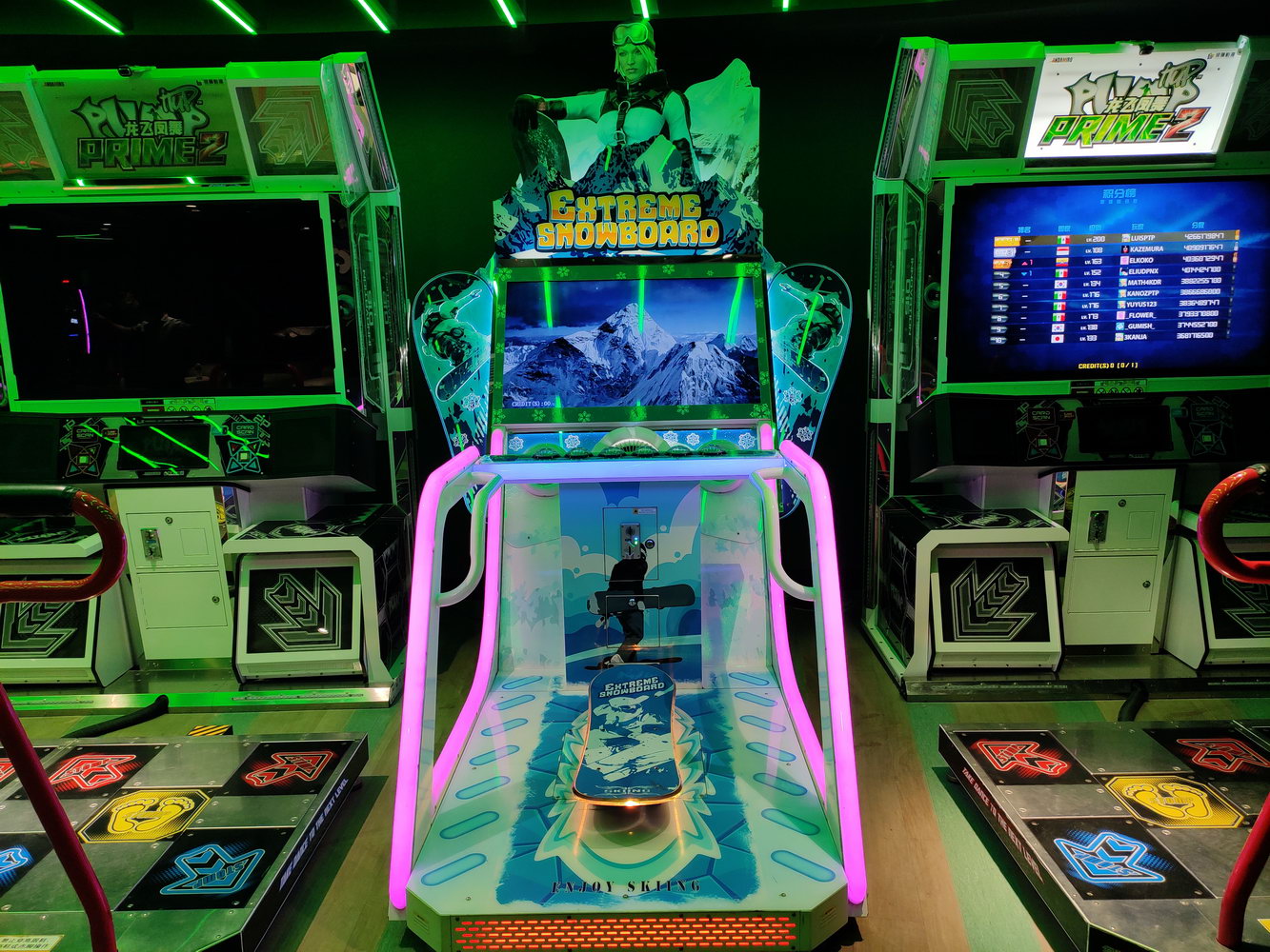
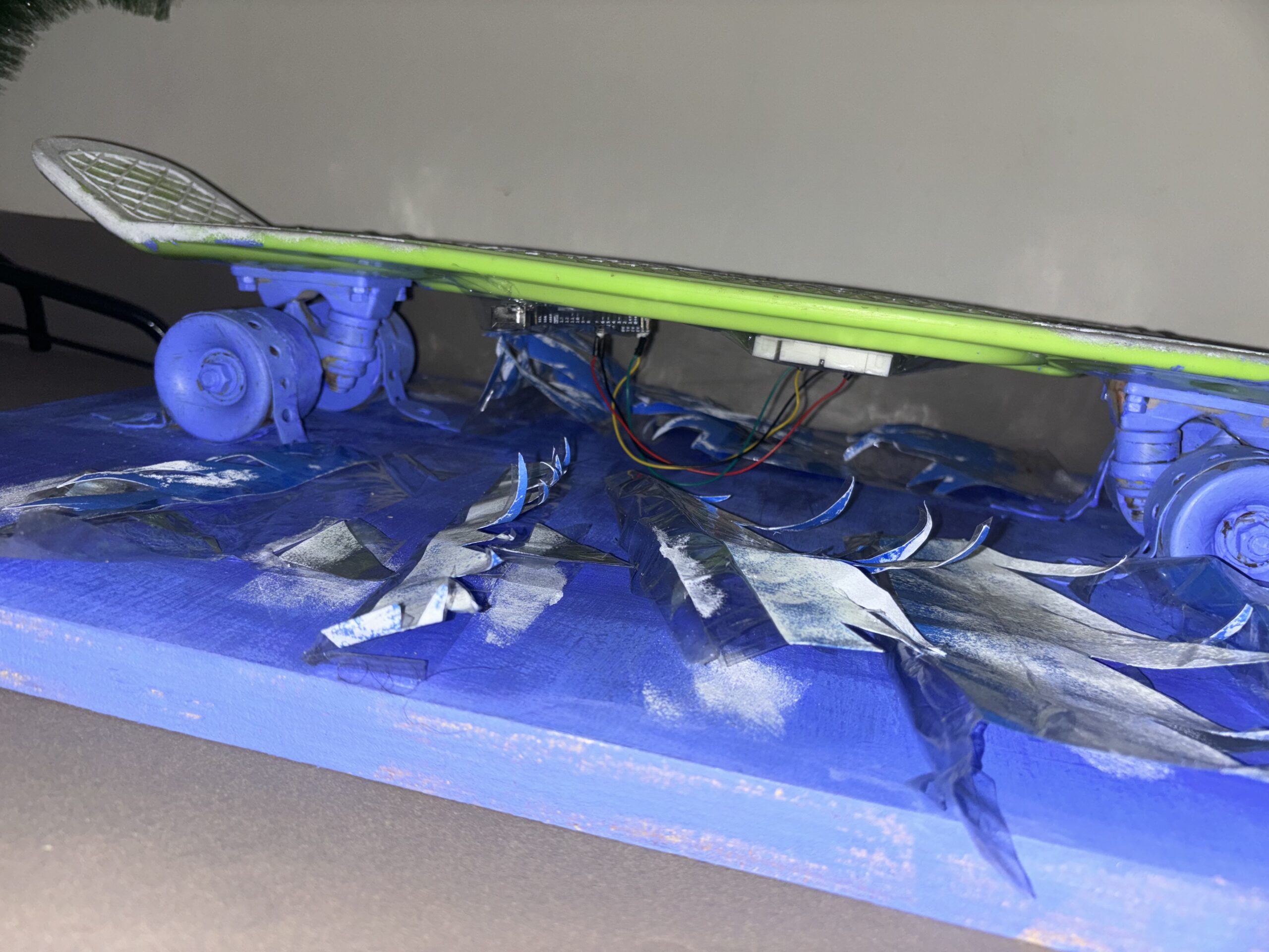
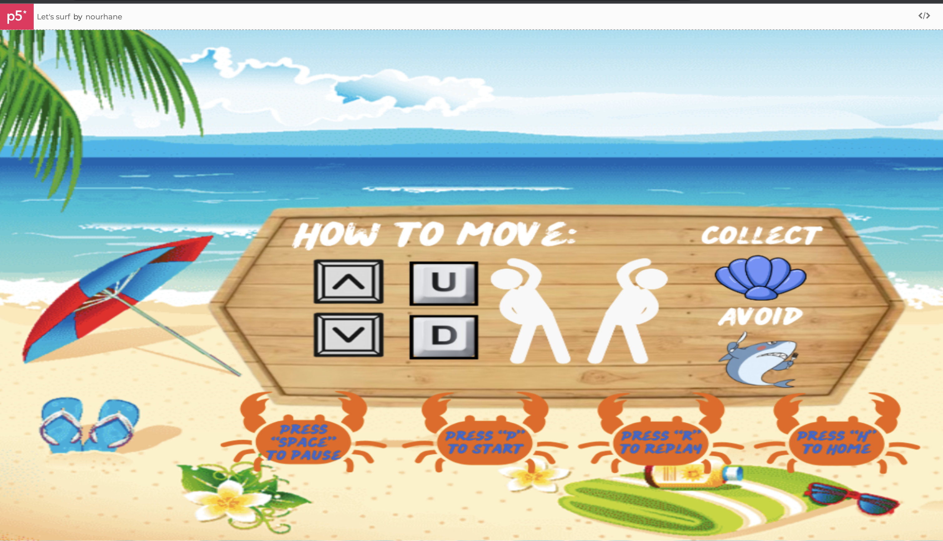
The end of an era! I’m proud to say that my game was a huge success and came out exactly how I envisioned it which was an immersive and interactive surfing simulator game. The idea came to me when I went to the arcade and saw a snowboarding game and it sparked my interest to know how it was made and if I could replicate it with something I enjoyed and miss which is surfing. The game uses a physical skateboard found in the IM lab equipped with an accelerometer to capture the player’s movements and mimics the snowboarding game actions, and a P5.js-based game that simulates surfing and where the user collects shells and avoids sharks (3 bites gets them killed) and the speed increases as the game goes on.
Inspiration:
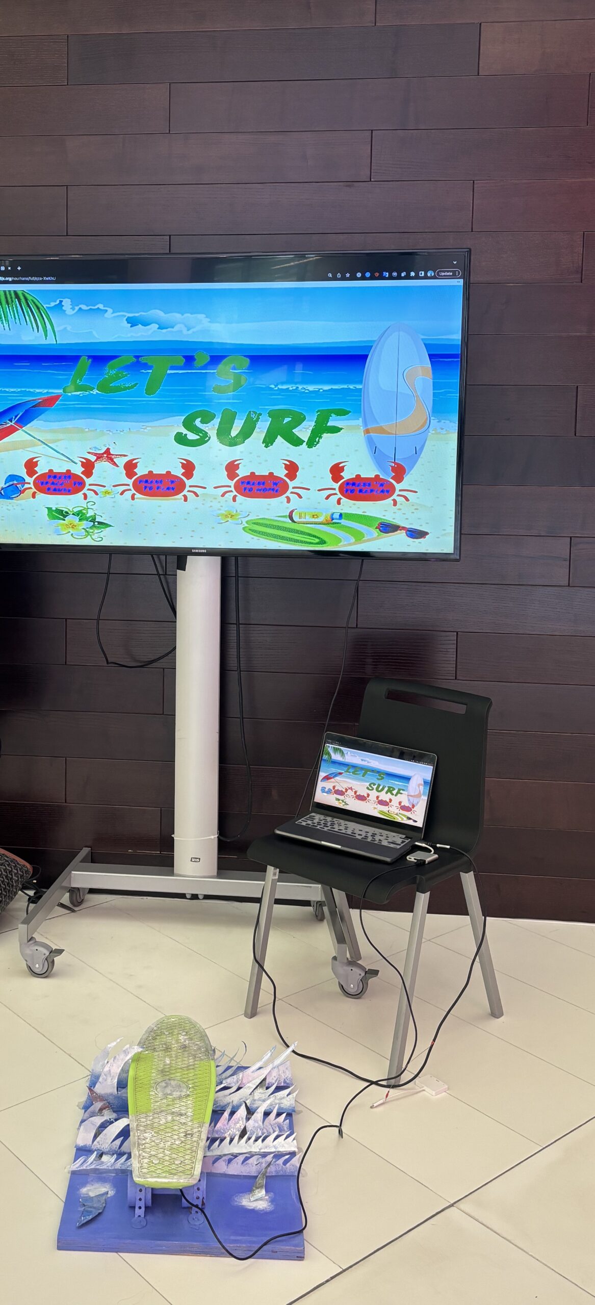
Results:
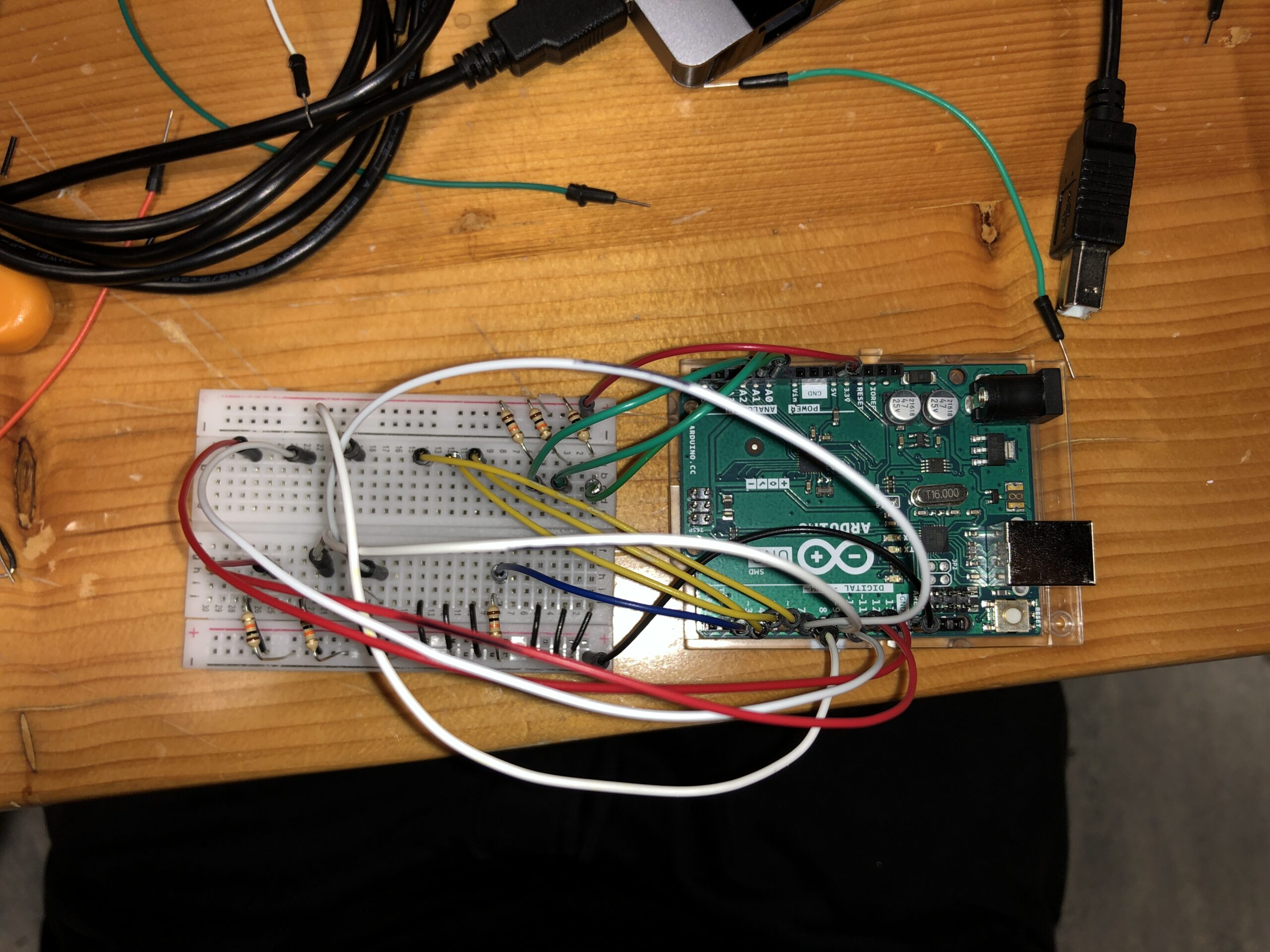
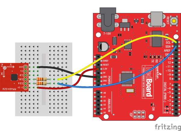
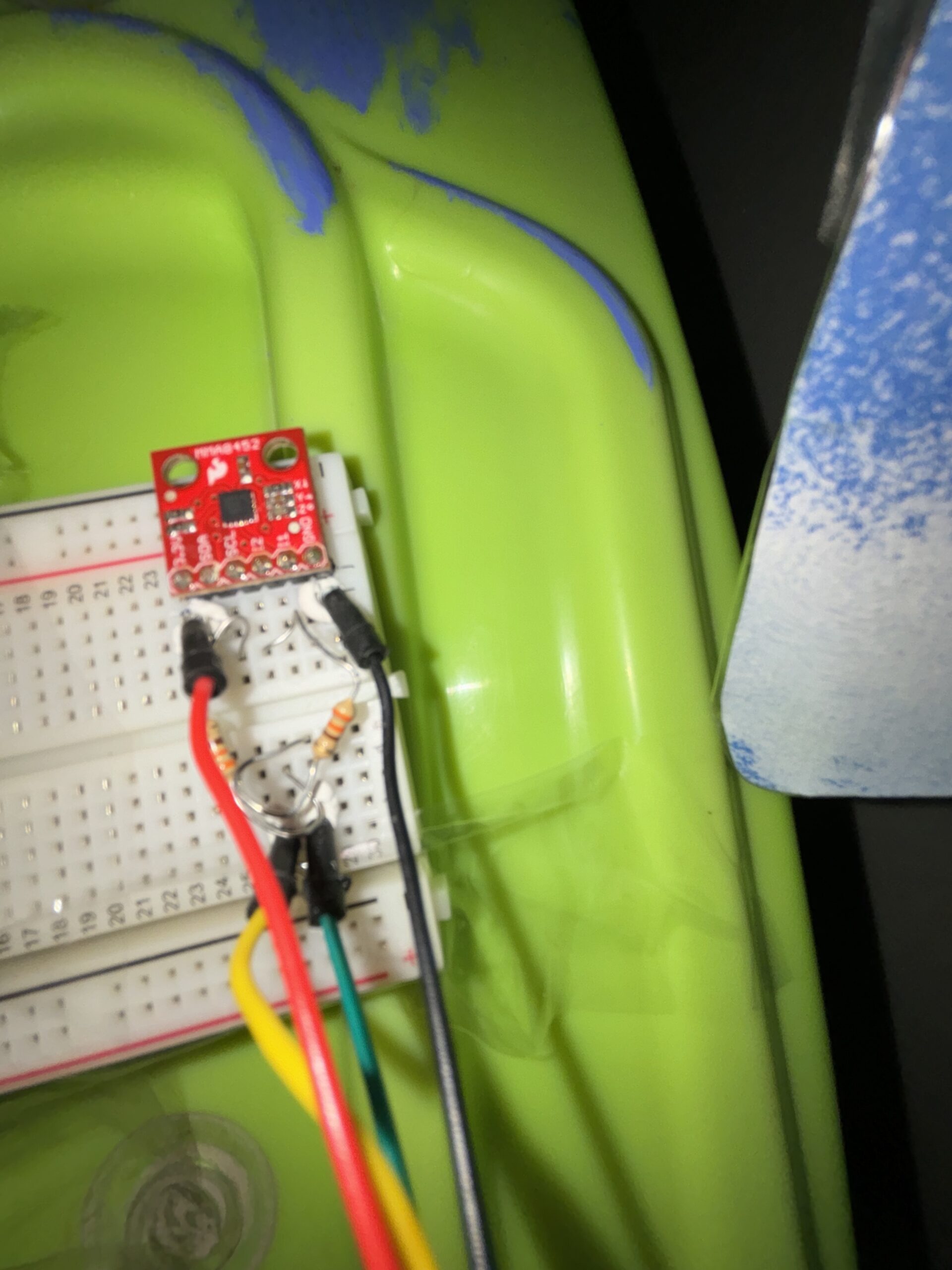
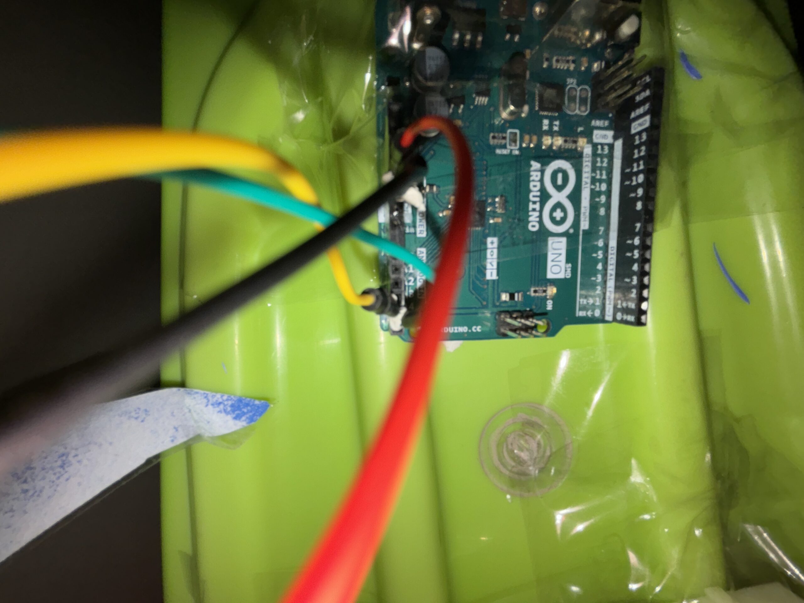
Circuit:
Schematic:
Real-life:
In Action:
Arduino Setup
Hardware: The core of the physical interaction is an accelerometer (like the MMA8452Q) mounted on a skateboard. This sensor detects the angle and intensity of the skateboard’s tilt.
Arduino Sketch:
Setup(): Initializes serial communication at a specific baud rate and sets up the accelerometer.
Loop(): Continuously reads the X and Y-axis data from the accelerometer. This data is formatted into a string (e.g., “X,Y”) and sent over serial communication to the P5.js sketch. Additionally, the sketch listens for incoming data from P5.js, which could be used for future features like haptic feedback based on game events.
Code:
// Define variables for images, screens, sounds, buttons, game state, and other parameters
let bgImage, bgImage2, catImage, sharkImage, shellImage; // Images for background, cat, shark, and shell
let welcomeScreen, instructionScreen, countdownScreen, gameOverScreen; // Images for different game screens
let bgSound, collectedSound, sharkBiteSound; // Sound effects for background, collecting items, and shark bite

let replayButton, homeButton, pauseButton; // Buttons for replay, home, and pause (not implemented in the code)
let catY, sharks = [], shells = []; // Y position of the cat, arrays for sharks and shells
let bgX1 = 0, bgX2, speed = 4, hits = 0, score = 0; // Background positions, game speed, hit count, and score
let waterLevel; // Level of the water in the game
let gameState = 'welcome'; // Current state of the game (e.g., welcome, play, paused)
let countdownValue = 3; // Countdown value before the game starts
let accelerometerX, accelerometerY; // Variables to store accelerometer values (for physical device interaction)

let left = 50; // Value to be sent to Arduino

let right = -50; // Value to be sent to Arduino

// Preload function to load images and sounds before the game starts
function preload() {
  // Load images
  bgImage = loadImage('background.png');
  bgImage2 = loadImage('background2.png');
  catImage = loadImage('cat.png');
  sharkImage = loadImage('shark.png');
  shellImage = loadImage('seashell.png');
  welcomeScreen = loadImage('welcome screen.png');
  instructionScreen = loadImage('instruction screen.png');
  countdownScreen = loadImage('countdown screen.png');
  gameOverScreen = loadImage('game over screen.png');

  // Setup sound formats and load sound files
  soundFormats('wav');
  bgSound = loadSound('background sound.wav');
  collectedSound = loadSound('collected.wav');
  sharkBiteSound = loadSound('shark bite.wav');
}

// Function to read data from a serial connection (presumably from an Arduino)
function readSerial(data) {
  // Check if the data is not null
  if (data != null) {
    let fromArduino = split(trim(data), ",");
    if (fromArduino.length == 2) { // Ensure the data has two parts (X and Y)
      accelerometerX = int(fromArduino[0]); // Parse X value
      console.log(accelerometerX); // Log X value (for debugging)
      accelerometerY = int(fromArduino[1]); // Parse Y value
      console.log(accelerometerY); // Log Y value (for debugging)
    }
  }
  let sendToArduino = left + "," + right + "\n"; // Prepare data to send back to Arduino
  console.log('writing'); // Log writing action (for debugging)
  writeSerial(sendToArduino); // Send data to Arduino (writeSerial function not provided in the code)
}

// Setup function runs once when the program starts
function setup() {
  createCanvas(windowWidth, windowHeight); // Create a canvas that fills the window
  catY = height / 2; // Set initial Y position of the cat
  waterLevel = height / 2.5; // Set water level position
  bgX2 = width; // Set initial position of the second background image
  bgSound.loop(); // Play background sound in a loop
}

// Draw function continuously executes the lines of code contained inside its block
function draw() {
  clear(); // Clear the canvas
  displayScreenBasedOnState(); // Call function to display the appropriate screen based on the game state
}

// Function to display the current screen based on the game's state
function displayScreenBasedOnState() {
  // Use a switch statement to handle different game states
  switch (gameState) {
    case 'welcome':
      image(welcomeScreen, 0, 0, width, height); // Display welcome screen
      break;
    case 'instructions':
      image(instructionScreen, 0, 0, width, height); // Display instructions screen
      break;
    case 'countdown':
      image(countdownScreen, 0, 0, width, height); // Display countdown screen
      displayCountdown(); // Call function to display countdown
      break;
    case 'play':
      playGame(); // Call function to play the game
      break;
    case 'paused':
      fill(173, 216, 230, 130); // Set color for pause screen overlay
      rect(0, 0, width, height); // Draw rectangle overlay
      fill(255); // Set color for text (white)
      textSize(48); // Set text size
      textAlign(CENTER, CENTER); // Set text alignment
      text("Game Paused", width / 2, height / 2); // Display pause text
      break;
    case 'gameOver':
      image(gameOverScreen, 0, 0, width, height); // Display game over screen
      noLoop(); // Stop the draw loop, effectively pausing the game
      break;
  }
}

// Function to display the countdown before the game starts
function displayCountdown() {
  fill(255); // Set color for text (white)
  textSize(70); // Set text size
  textAlign(CENTER, CENTER); // Set text alignment
  text(countdownValue, width / 2, height / 2); // Display countdown number

  // Decrease countdown value every second
  if (frameCount % 60 === 0 && countdownValue > 0) {
    countdownValue--;
  } else if (countdownValue === 0) {
    gameState = 'play'; // Change game state to play when countdown reaches 0
    countdownValue = 3; // Reset countdown value for next time
  }
}

// Function to handle the gameplay
function playGame() {
  backgroundScrolling(); // Call function to scroll the background
  displayCat(); // Call function to display the cat
  handleSharks(); // Call function to handle sharks
  handleSeashells(); // Call function to handle seashells
  displayScore(); // Call function to display the score
  increaseDifficulty(); // Call function to increase game difficulty over time
}

// Function to handle background scrolling
function backgroundScrolling() {
  image(bgImage, bgX1, 0, width, height); // Draw the first background image
  image(bgImage2, bgX2, 0, width, height); // Draw the second background image
  bgX1 -= speed; // Move the first background image leftward
  bgX2 -= speed; // Move the second background image leftward

  // Reset background positions for continuous scrolling effect
  if (bgX1 <= -width) bgX1 = bgX2 + width;
  if (bgX2 <= -width) bgX2 = bgX1 + width;
}

// Function to display the cat character
function displayCat() {
  // Move the cat up or down based on key presses or accelerometer data
  if (keyIsDown(UP_ARROW) || keyIsDown(85)) catY -= 5; // Move up with UP_ARROW or 'U' key
  if (keyIsDown(DOWN_ARROW) || keyIsDown(68)) catY += 5; // Move down with DOWN_ARROW or 'D' key
  catY = accelerometerY + 500; // Position cat based on accelerometer data
  catY = constrain(catY, waterLevel, height - 100); // Constrain cat's movement within the canvas
  image(catImage, 50, catY, 125, 125); // Draw the cat image at the calculated position
}

// Function to handle sharks in the game
function handleSharks() {
  // Generate new sharks at regular intervals
  if (frameCount % 150 === 0) {
    let sharkY = random(waterLevel - 1, height - 90); // Random Y position for sharks
    sharks.push({ x: width, y: sharkY }); // Add new shark to the sharks array
  }

  // Loop through all sharks and update their positions
  for (let i = sharks.length - 1; i >= 0; i--) {
    let shark = sharks[i];
    shark.x -= speed; // Move shark leftward
    image(sharkImage, shark.x, shark.y, 300, 300); // Draw shark image

    // Check for collision between cat and shark
    if (dist(30, catY, shark.x, shark.y) < 84) {
      hits++; // Increase hits count
      sharkBiteSound.play(); // Play shark bite sound
      sharks.splice(i, 1); // Remove the collided shark from the array
      if (hits >= 3) {
        gameState = 'gameOver'; // End the game after 3 hits
      }
    }
  }
}

// Function to handle seashells in the game
function handleSeashells() {
  // Generate new seashells at regular intervals
  if (frameCount % 300 === 0) {
    let shellY = random(waterLevel + 100, height - 70); // Random Y position for seashells
    shells.push({ x: width, y: shellY }); }// Add new shell to the shells array
   // Loop through all seashells and update their positions
  for (let i = shells.length - 1; i >= 0; i--) {
    let shell = shells[i];
    shell.x -= speed; // Move shell leftward
    image(shellImage, shell.x, shell.y, 50, 50); // Draw shell image

    // Check for collision between cat and shell
    if (dist(50, catY + 62.5, shell.x, shell.y) < 100) {
      score++; // Increase score
      shells.splice(i, 1); // Remove the collected shell from the array
      collectedSound.play(); // Play sound upon collecting a shell
    }
  }
}

// Function to display the game score
function displayScore() {
  fill(255); // Set text color to white
  textSize(27); // Set text size
  text('Score: ', 70, 30); // Display "Score: "
  text(score, 150, 30); // Display the current score
  image(shellImage, 110, 11, 30, 30); // Display shell icon next to score

  text('Bitten: ', 70, 68); // Display "Bitten: "
  text(hits, 150, 70); // Display the number of times the cat has been bitten
  image(sharkImage, 73, 17, 100, 100); // Display shark icon next to hits
}

// Function to gradually increase the difficulty of the game
function increaseDifficulty() {
  if (frameCount % 500 === 0) speed += 0.5; // Increase the speed of the game every 500 frames
}

// Function to toggle the game's pause state
function togglePause() {
  if (gameState === 'play') {
    gameState = 'paused'; // Change game state to paused
    noLoop(); // Stop the draw loop, effectively pausing the game
  } else if (gameState === 'paused') {
    gameState = 'play'; // Resume playing the game
    loop(); // Restart the draw loop
  }
}

// Function that handles key press events
function keyPressed() {
  if (key === 'u') { // If 'u' is pressed, set up serial communication
    setUpSerial(); // Function to set up serial communication (not provided in the code)
    console.log('u clicked'); // Log action for debugging
  }
  else if (keyCode === 32) { // If space bar is pressed, toggle pause
    togglePause();
  } else if (keyCode === 82) { // If 'R' is pressed, reset the game
    resetGame();
  } else if (keyCode === 72) { // If 'H' is pressed, go to home screen
    homeGame();
  } else if (key === 'p' || key === 'P') { // If 'P' is pressed, proceed to the next game state
    if (gameState === 'welcome') {
      gameState = 'instructions';
    } else if (gameState === 'instructions') {
      gameState = 'countdown';
    }
  }
}

// Function to reset the game to its initial state
function resetGame() {
  sharks = []; // Clear the sharks array
  shells = []; // Clear the shells array
  score = 0; // Reset score to 0
  hits = 0; // Reset hits to 0
  catY = height / 2; // Reset the cat's position to the middle
  gameState = 'countdown'; // Change the game state to countdown
  countdownValue = 3; // Reset the countdown value
  loop(); // Restart the draw loop
}

// Function to return to the game's home screen
function homeGame() {
  sharks = []; // Clear the sharks array
  shells = []; // Clear the shells array
  score = 0; // Reset score to 0
  hits = 0; // Reset hits to 0
  catY = height / 2; // Reset the cat's position to the middle
  gameState = 'welcome'; // Change the game state to welcome
  countdownValue = 3; // Reset the countdown value
  loop(); // Restart the draw loop
}

// Function to handle window resizing
function windowResized() {
  resizeCanvas(windowWidth, windowHeight); // Resize the canvas to the new window size
}

//ARDUINO CODE
// #include <Wire.h>
// #include <SparkFun_MMA8452Q.h>  // Include the SparkFun MMA8452Q accelerometer library

// MMA8452Q accel;  // Create an instance of the MMA8452Q class

// void setup() {
//   Serial.begin(9600);
//   Wire.begin();  // Initialize I2C communication


//   if (accel.begin() == false) {  // Initialize the accelerometer
//     Serial.println("Not Connected. Please check connections and restart the sketch.");
//     while (1);
//   }

//   // Start the handshake
//   while (Serial.available() <= 0) {

//     Serial.println("0,0");           // Send a starting message to p5.js
//     delay(300);                      // Wait for a bit
//   }
// }

// void loop() {
//   // If there is data from p5.js, read it and blink the LED
//   if (Serial.available()) {

//     // Read the incoming data from p5.js
//     int left = Serial.parseInt();
//     int right = Serial.parseInt();


//   }

//   // Read data from the accelerometer
//   if (accel.available()) {
//     accel.read();  // Read the accelerometer data
//     int x = accel.getX();  // Get the X-axis data
//     int y = accel.getY();  // Get the Y-axis data
//     int z = accel.getZ();  // Get the Z-axis data

//     // Send the accelerometer data to p5.js
//     Serial.print(x);
//     Serial.print(",");
//     Serial.println(y);
//   }

//   delay(100);  // Delay before the next loop iteration
// }
P5.js:
Game Environment: The game features various interactive elements – a cat character, shark obstacles, collectible seashells, and a scrolling background to simulate underwater movement.
Control Mechanism: The game interprets the serial data received from the Arduino as control commands for the cat character. The X and Y values from the accelerometer dictate the cat’s vertical position on the screen.
Game States: Includes multiple states like ‘welcome’, ‘instruction’, ‘play’, ‘pause’, and ‘game over’, each managed by different functions and displaying appropriate screens.
Game Dynamics:
Sharks appear at random intervals and positions. Collisions between the cat and sharks result in a ‘hit’.
Seashells also appear randomly and can be collected for points.
The game’s difficulty increases over time by gradually speeding up the background scroll and the frequency of obstacles.
Interaction Design:
Physical Interaction: The player stands on the skateboard. By tilting the board, they control the cat’s vertical position. The degree of tilt corresponds to the direction of the cat’s movement.
Visual and Auditory Feedback: The game provides immediate visual responses to the player’s actions. Collecting shells and colliding with sharks triggers distinct sound effects.
Communication Between Arduino and P5.js:
Serial Communication: Utilizes the P5.serialport library. The Arduino sends accelerometer data, which P5.js receives, parses, and uses for gameplay control.
Data Format and Handling: The data is sent as a comma-separated string of X and Y values (e.g., “45,-10”). P5.js parses this string and maps these values to the cat’s movement.
Highlights:
Innovative Control Mechanism: The use of a skateboard with an accelerometer as a game controller stands out as a unique feature. This approach not only adds a physical dimension to the gaming experience but also encourages physical activity.
Responsive and Intuitive Gameplay: One of the key successes of the project is the fluid responsiveness of the game to the skateboard’s movements. The calibration of the accelerometer was fine-tuned to ensure that even subtle tilts are accurately reflected in the game, providing an intuitive control system that players can easily adapt to.
Engaging Game Environment: The theme complete with sharks, seashells, and a dynamic background, creates a visually appealing and engaging world. This immersive setting, combined with sound effects for different interactions (like collecting shells and shark encounters), enriches the gaming experience.
Challenges:
Calibrating the Accelerometer: One of the main challenges was calibrating the accelerometer to accurately reflect the skateboard’s movements in the game. This required extensive testing and adjustments to ensure that the data from the accelerometer translated into appropriate movements of the cat character without being overly sensitive or unresponsive.
Understanding Accelerometer Usage: Learning to effectively use the accelerometer was a considerable challenge. It involved understanding the principles of motion and tilt detection, and then implementing this understanding in code that could accurately interpret and utilize the data.
Serial Communication Issues: Ensuring consistent and error-free serial communication between the Arduino and P5.js was a significant challenge. This involved not only setting up the communication channel but also ensuring that the data was sent, received, and parsed correctly, without any loss or corruption.
Future Ideas:
Multiplayer Capability: Adding a multiplayer option could transform the game into a more social and competitive experience, possibly even allowing for collaborative play.
Enhanced Physical Design: Improving the skateboard’s design for increased stability, comfort, and safety would make the game more accessible to a wider range of players.
Adding Levels: Implementing difficulty levels based on the player’s performance could make the game more engaging and challenging for players of all skill levels.
Haptic Feedback Integration: Incorporating haptic feedback on the skateboard based on game events could significantly enhance the immersive quality of the game.
High Score: Adding a high score in the end in order to keep track of everyone’s score so that they can keep trying to beat it.
Following the showcase, I am just extremely satisfied and proud of my entire game and how it turned out because a lot of people really loved and enjoyed it a lot and kept returning to try to beat their score again and even if it drove me crazy several times I’m so glad that I persevered and made something that I’m proud of.
Initially, users couldn’t believe that the skateboard controls the game since for them it was impossible to make that as a student and so they try to use the keyboard keys to control the game and when they see that it doesn’t work they get up on the skateboard with still a lot of reluctancy and asking me several times if it’s safe and if it works and if that’s what they should do (even though I have the exact instructions of what they should do in the screen but I think having using keys on the screen instructions is also what caused this confusion since the reason I added it was in order to make the game usable even without the Arduino but once the Arduino is connected it stops the keys from working). Once they start playing they are impressed and start asking all kinds of questions about how I did it especially because I hid the circuit so well so they didn’t realize that was how it worked until I explain it. I think for the future I could add more specific instructions telling users to check whether the game is physical or online or maybe even a how to video. The game once explained is very self explanatory since I give them time to get used to the board and how to use it before the sharks start appearing. What i feel like I have to explain the most tho is just the direction to tilt to go to what direction but i don’t think there’s a way to make it better since it depends on what side people choose to stand which makes their instructions specific for them.
My final project idea is to develop an immersive and interactive surfing simulator game. The idea came to me when I went to the arcade and saw a snowboarding game and it sparked my interest to know how it was made and if I could replicate it with something I enjoyed and miss which is surfing. This game will use a physical skateboard found in the IM lab equipped with an accelerometer to capture the player’s movements, and a P5.js-based game that simulates a surfing and will have the concept of collecting and avoiding.
Inspo:
Components
1. Arduino Setup: Hardware: A skateboard with an accelerometer attached to its bottom. The accelerometer will detect tilt and motion, translating the player’s physical movements into digital inputs.
Functionality: The Arduino will continuously read the accelerometer data to determine the orientation and motion of the skateboard. This data will be sent to the P5.js game to control the virtual surfer’s movements.
2. P5.js Game Development: Visual Interface: A surfing game created in P5.js, displaying a cat surfer surfing through the ocean. The game will have an avoiding and collecting concept.
Game Mechanics: The game will respond to the skateboard’s movements, controlling the surfer’s actions like speeding up, slowing down, turning, and performing tricks.
Feedback and Scoring: Visual and auditory feedback will be provided based on the player’s performance, along with a scoring system and life left.
3.Interaction Flow:
– The player stands on the skateboard and starts the game through a simple interface.
– As the player tilts and moves the skateboard, the accelerometer sends this data to the Arduino.
– The Arduino processes these movements and sends corresponding commands to the P5.js game.
– The game responds in real-time, translating these movements into the surfer’s actions on the screen.
– The player receives visual and audio feedback from the game, creating an engaging loop of action and response.
4.Design Considerations: Responsiveness: Ensuring that it doesn’t feel or look shaky between physical movements and digital responses for a seamless experience. User Safety: Designing the physical setup to be safe and stable for users of different skill levels. Game Challenge: Balancing the game difficulty to be both fun and challenging, encouraging players to improve their skills. Aesthetic Appeal: Creating an attractive and immersive game environment that enhances the overall experience.
5.Potential Challenges:
– Ensuring accurate and consistent data transmission from the accelerometer to the game.
– Balancing the physical skateboard movements with the digital game mechanics for a realistic surfing experience.
– Optimizing the game’s performance to prevent lag or glitches that could disrupt the immersive experience.
Conclusion
This project aims to create a novel gaming experience that blends physical activity with digital interaction, using Arduino and P5.js. It not only introduces a new way to play and enjoy a surfing game but also encourages physical movement, making gaming a more active experience.


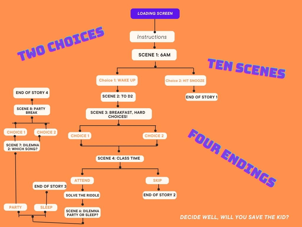 As you can see, the story is pretty short since it’s a mashup (but also because of time constraints!). I counted 10 scenes with 4 endings.
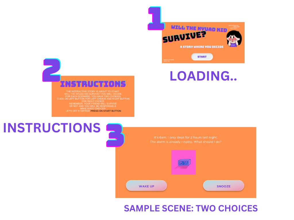
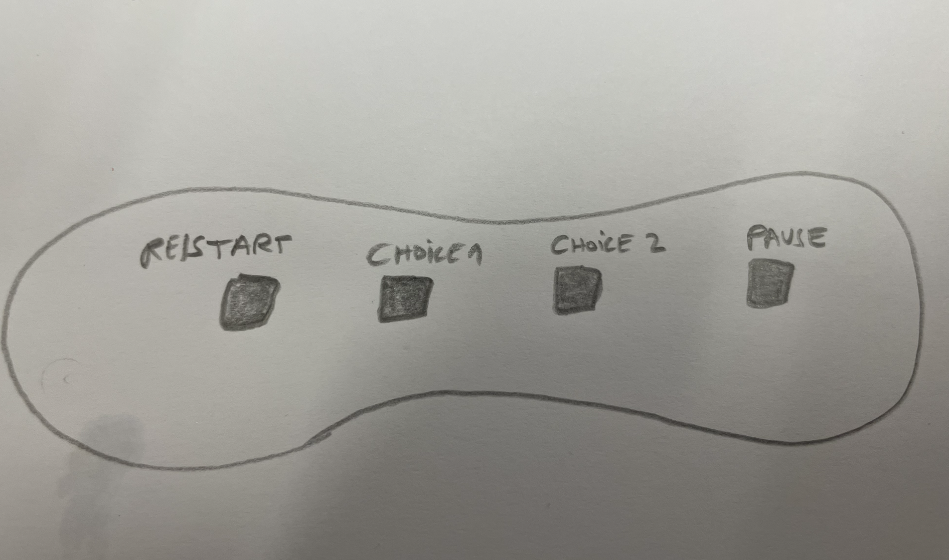

 And this is how users interact with it: