Final Project – PixelPals

Concept:

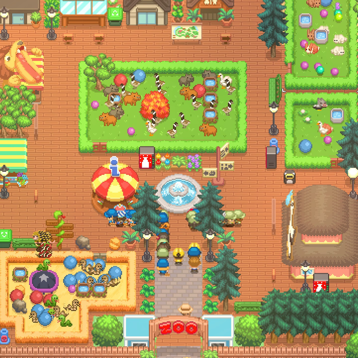
This project follows my initial idea of making a digital petting zoo. The name of this zoo is PixelPals. In this petting zoo, you are able to approach different animals and make different interactions with them based on their needs and personalities. The theme and design is quite adorable, aiming to create an atmosphere of comfort and fun. The soundtrack of the background music is from the Nintendo Game, Animal Crossing, something very similar to this project. This project also includes a dedicated control box.

https://editor.p5js.org/Yupuuu/full/2L2O-pC8e

Challenges and Highlights:

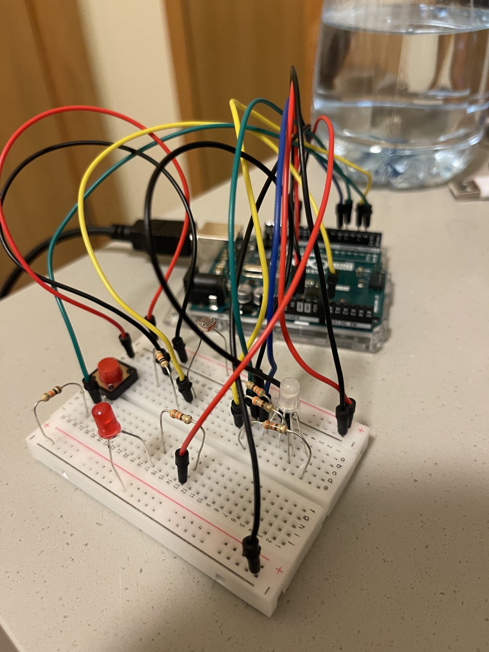
The most difficult challenge I had was the serial communication. It took me sometime understand how the serial communication truly works so that I could send more complicated codes. Designing levels of the experience is also hard: it’s important to decide which levels one animal uses, and how to differentiate among all these animals, etc. This is especially difficult because I had to deal with two ends of the communication at the same time. Therefore, it took me a lot of time to figure these things out. And also, sometimes the circuit itself did not work and I had to try some methods such as resetting the Arduino or rewiring things to make it work.

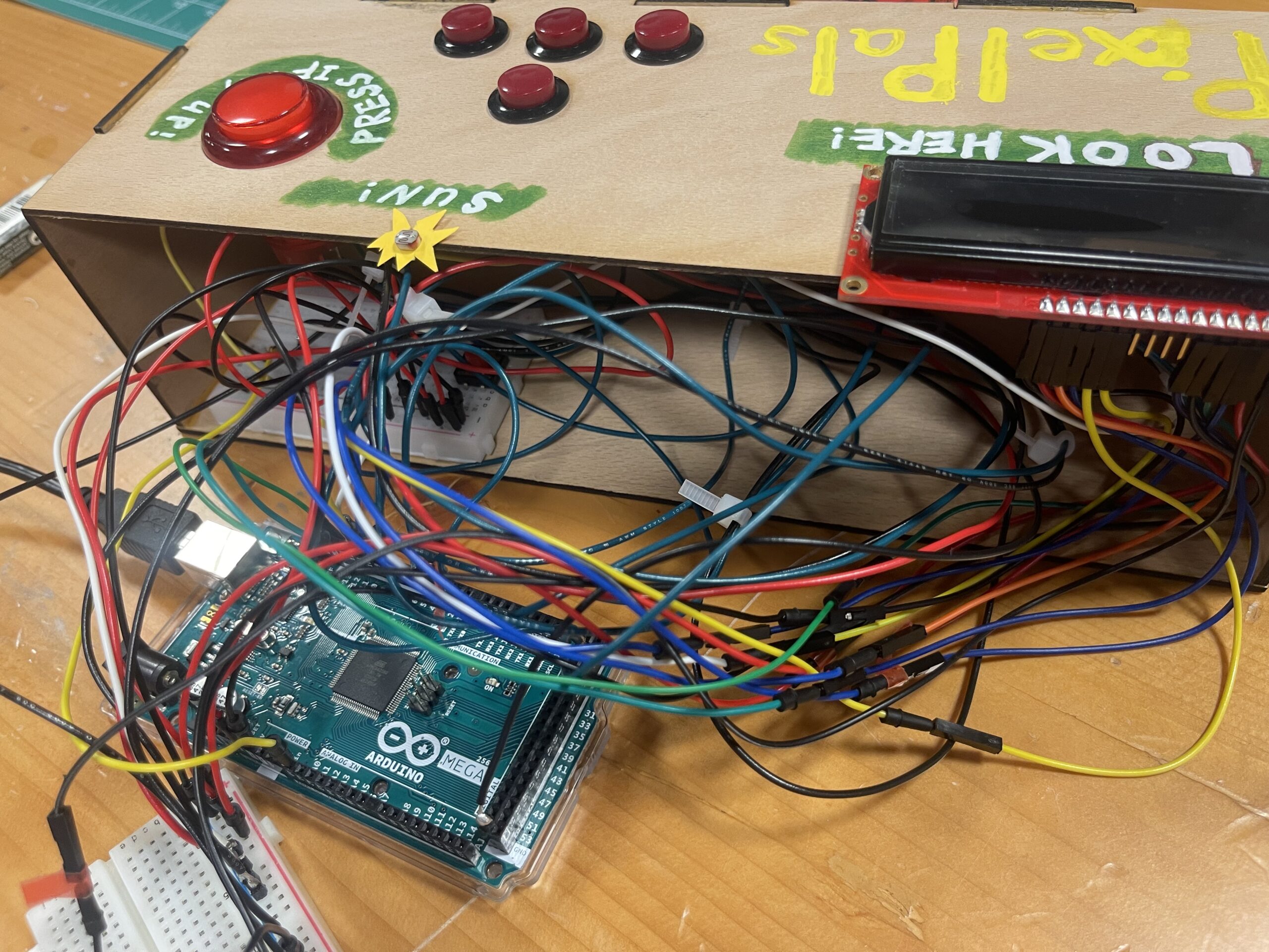
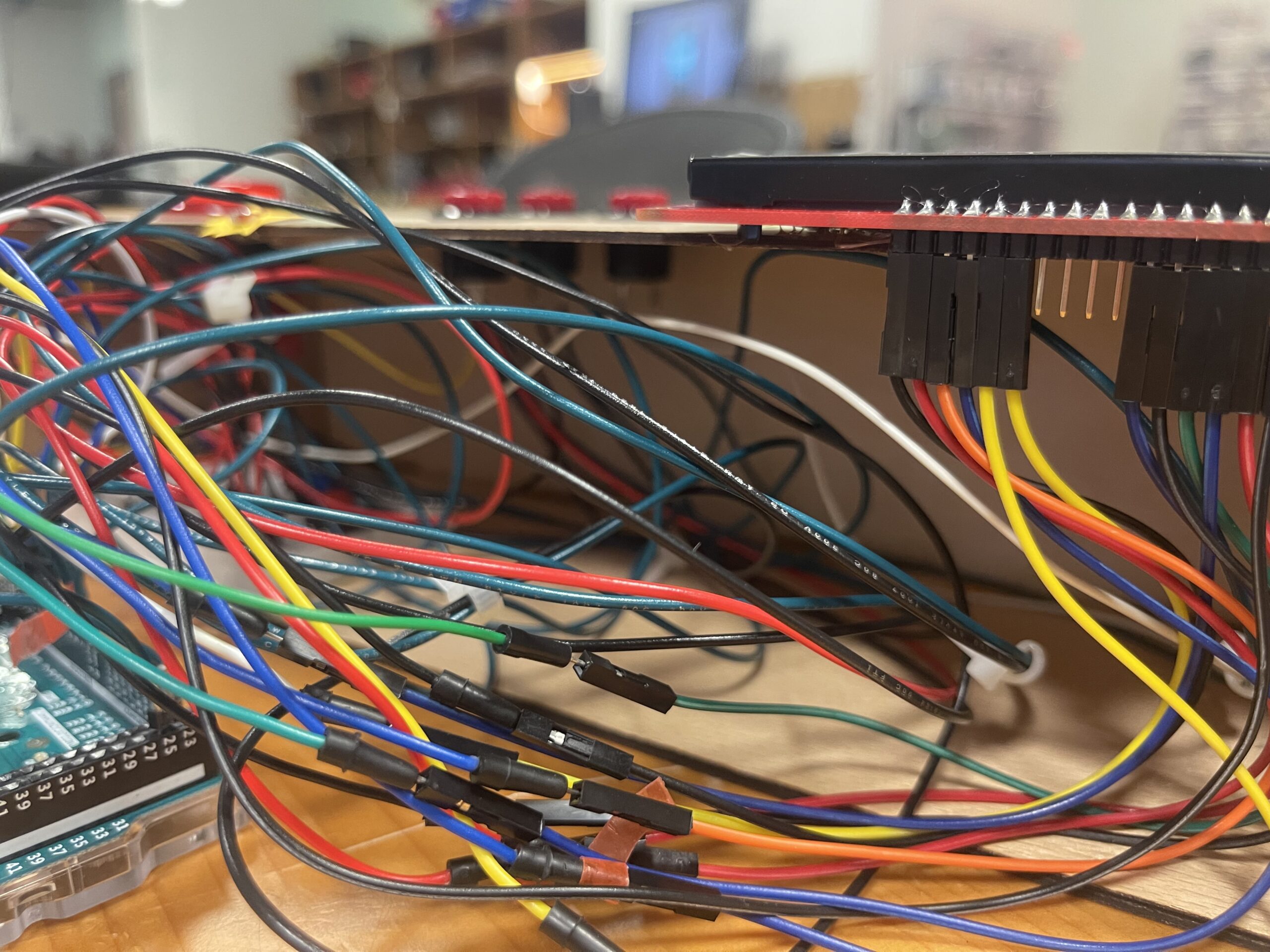
Another problem I ran into the wiring the wires and making the control panel. The control panel is smaller than I thought when I was using the laser cutter to make it. This gave me a hard time putting everything into this enclosed box. In fact, I am still not able to put all wires into it. But one advantage of keeping things outside is that I can easily spot the problem if anything happens. However, this is still a lesson learnt: always make the box bigger than I think.

I am especially proud of using many different features in this single project, including state machine, spritesheet, colliders, etc. All these parts work smoothly with each other to make this project possible. And I am also glad how I used fours buttons to complete several different tasks. Allocating these buttons is also important for the implementation of this project.

Arduino code: https://drive.google.com/drive/folders/1tKOEiyYHFteIk_WYt9-tBES8K4-c9bhL?usp=sharing

VIDEO: IMG_1755

Control Panel: Arduino  Mega,  LCD  Display,  Buttons,  Light  Sensor
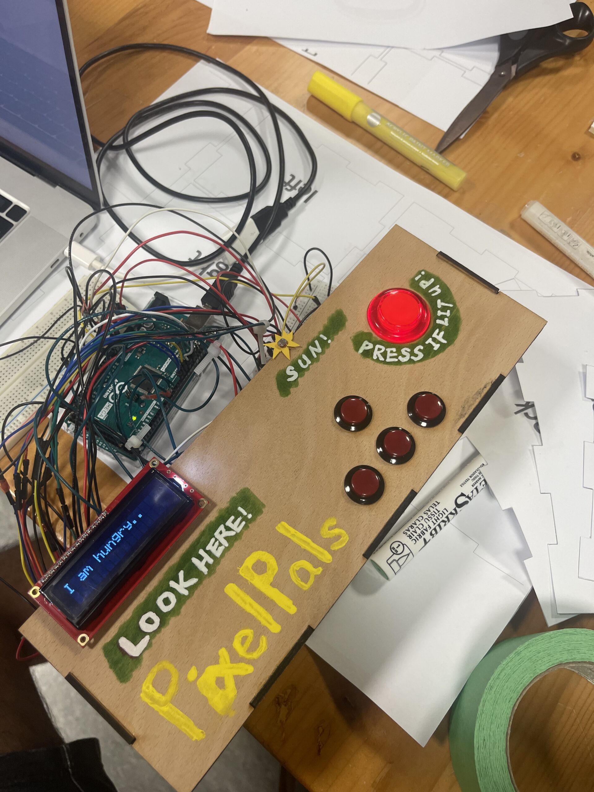
User Testing

The current control panel is a result of user testing. Originally, there were no instructions at all. Especially when it came to the light sensor, people who did not know what it was had no idea what it could do and how it could relate to the owl. Therefore, I decided to add a shape of the sun to indicate that this can represent a sun and you need to cover this sun for the owl to sleep. Following this, I added instructions to the control panel. However, as a relaxing experience, I do not want the player to spend a lot of time reading the instructions. Therefore, I ended up using some simple illustrations and words to guide the player.

(After the showcase) It was interesting that almost nobody followed the instructions before I told them to. They liked pushing the button even when it was not lit up. And they never read what was on the LCD screen. The only persons who read them were kids. Probably this game was meant for kids. This really shows me the gap between the designed experience and the actual experience people have. It actually reflects on one of our readings that the interactive media artists should let the audience explore on themselves. Obviously, my project is not such a good example in which audience should be allowed to freely explore it as it might break my project… However, overall, people could understand what my project was about and made a laugh when they actually read the texts on the LCD screen!

Reflection & Improvements

This project is very interesting. It prompted me to utilize all the skills I learnt in this class with fabrication skills make this project. It is very satisfactory to see the final product. Reflecting on this project, I realized the power of physical computing and how the hardware and softwire can work together to create unique experiences. However, one of my initial ideas was to create an animal like controller that can act like an animal. However, that would require much more physical constructions, which I did not have enough time for this time. In this future improvement, this could be added, and more interactions could be added to more animals in this zoo. Maybe some customization functions could also be added to make this experience more interesting and personal.

Week 12 – Final Project Proposal and Design Documentation

Concept

For the final project, I have committed to the digital petting zoo idea, in which the user can interact with different animals on screen with one physical model and other props.

Design Documentation

p5: In this project, p5js will primarily be the user interface of the petting zoo. It will show the mapping of the zoo, the animals, instructions, and the need of different animals.

The general appearance should represent something like this (but surely a simplistic version):

Let's Build A Zoo review: an absorbing tycoon game that relishes chaos | Rock Paper Shotgun

This interface will be composed of several colliders and the user can walk around and trigger different interactions. A wireframe of this idea is live on p5js now: The big blocks are animal areas and the small one is the player. The player now can walk around with the arrow keys on the keyboard and different messages will be displayed on the LCD screen connected to the Arduino (will explained below) when the player collides with different blocks, showing that they are entering different animal areas.

Arduino: The Arduino will be the controller of the player and the place will physical interactions with the animals on the screen could happen. I plan to craft a model that represents the animal that will be in the zoo with a LCD display that will tell the player which animal it is based on the location of the player in the zoo. There might be other parts connected to this model, such as servo motors and other sensors, which make the interactions possible. There will also be a control panel with four buttons, allowing the player to walk in the zoo, just like the arrow buttons on the keyboard.

Week 11 – Final Project Idea

Concept: A Digital Petting Zoo

For the final project, as we are required to combine both Arduino and p5js, I decided to do a digital petting zoo. I take the inspiration from an actual petting zoo, which looks like this:

Petting zoos under threat following health inquiry

In this digital petting zoo, the p5js will act like a map of the zoo and shows the information about the animals. The visitor will be able to navigate the zoo using controllers connected to Arduino. In this zoo, I plan to have three to four animals. For these animals, I plan to make physical prototypes using cardboards and other materials. These physical prototypes will be equipped with different sensors according to different animals so that the visitor can interact with them. For example, some shy animal may have a distance sensor while outgoing one might have a light sensor so that it can sense the petting of the visitor.

Additionally, to add some fun to the experience, there will be some tasks for the visitor to complete, such as feeding them, petting them, etc. This sort of imitates the famous old device, a Tamagotchi:

The user interface should represent something like this:

MatchyGotchy Z on Steam

Therefore, this project aims at making the visitor feel like walking around a petting zoo as well taking care of the animals there using Arduino and p5js.

Week 11 – Serial Communication

For this assignment, I collaborated with Shahd. We based our project on the example codes and made changes as we see appropriate. Shahd did the second exercise and I did the first exercise. We worked together to complete the third exercise.

Video:

Exercise 1:

p5 sketch:

int leftLedPin = 7;
int rightLedPin = 4;


void setup() {
 // Start serial communication so we can send data
 // over the USB connection to our p5js sketch
 Serial.begin(9600);


 // We'll use the builtin LED as a status output.
 // We can't use the serial monitor since the serial connection is
 // used to communicate to p5js and only one application on the computer
 // can use a serial port at once.
 pinMode(LED_BUILTIN, OUTPUT);


 // Outputs on these pins
 pinMode(leftLedPin, OUTPUT);
 pinMode(rightLedPin, OUTPUT);


 // Blink them so we can check the wiring
 digitalWrite(leftLedPin, HIGH);
 digitalWrite(rightLedPin, HIGH);
 delay(200);
 digitalWrite(leftLedPin, LOW);
 digitalWrite(rightLedPin, LOW);


 // start the handshake
  while (Serial.available() <= 0) {
    digitalWrite(LED_BUILTIN, HIGH);  // on/blink while waiting for serial data
    Serial.println("0,0");            // send a starting message
    delay(300);                       // wait 1/3 second
    digitalWrite(LED_BUILTIN, LOW);
    delay(50);
  }
}


void loop() {
 // wait for data from p5 before doing something
 while (Serial.available()) {
   digitalWrite(LED_BUILTIN, HIGH);  // led on while receiving data


   if (Serial.read() == '\n') {


     int sensor = analogRead(A1);  //potentiometer
     Serial.println(sensor);
   }
 }
 digitalWrite(LED_BUILTIN, LOW);
}

Exercise 2:

int leftLedPin = 6;


void setup() {
 // Start serial communication so we can send data
 // over the USB connection to our p5js sketch
 Serial.begin(9600);


 // We'll use the builtin LED as a status output.
 // We can't use the serial monitor since the serial connection is
 // used to communicate to p5js and only one application on the computer
 // can use a serial port at once.
 pinMode(LED_BUILTIN, OUTPUT);


 // Outputs on these pins
 pinMode(leftLedPin, OUTPUT);


 // start the handshake
 while (Serial.available() <= 0) {
   digitalWrite(LED_BUILTIN, HIGH);  // on/blink while waiting for serial data
   Serial.println("0,0");            // send a starting message
   delay(200);                       // wait 1/3 second
   digitalWrite(LED_BUILTIN, LOW);
   delay(200);
 }
}


void loop() {
 // wait for data from p5 before doing something
 while (Serial.available()) {
   digitalWrite(LED_BUILTIN, HIGH);  // led on while receiving data


   int brightness = Serial.parseInt();
   analogWrite(leftLedPin, brightness);
   if (Serial.read() == '\n') {
     Serial.println("0,0");
   }
 }
 digitalWrite(LED_BUILTIN, LOW);
}


Exercise 3:

int leftLedPin = 7;
int rightLedPin = 4;


void setup() {
 // Start serial communication so we can send data
 // over the USB connection to our p5js sketch
 Serial.begin(9600);


 // We'll use the builtin LED as a status output.
 // We can't use the serial monitor since the serial connection is
 // used to communicate to p5js and only one application on the computer
 // can use a serial port at once.
 pinMode(LED_BUILTIN, OUTPUT);


 // Outputs on these pins
 pinMode(leftLedPin, OUTPUT);
 pinMode(rightLedPin, OUTPUT);


 // Blink them so we can check the wiring
 digitalWrite(leftLedPin, HIGH);
 digitalWrite(rightLedPin, HIGH);
 delay(200);
 digitalWrite(leftLedPin, LOW);
 digitalWrite(rightLedPin, LOW);


 // start the handshake
  while (Serial.available() <= 0) {
    digitalWrite(LED_BUILTIN, HIGH);  // on/blink while waiting for serial data
    Serial.println("0,0");            // send a starting message
    delay(300);                       // wait 1/3 second
    digitalWrite(LED_BUILTIN, LOW);
    delay(50);
  }
}


void loop() {
 // wait for data from p5 before doing something
 while (Serial.available()) {
   digitalWrite(LED_BUILTIN, HIGH);  // led on while receiving data


   int LED_STATE = Serial.parseInt();
   //int right = Serial.parseInt();
   if (Serial.read() == '\n') {
     digitalWrite(rightLedPin, LED_STATE);
     int sensor2 = analogRead(A1);
     delay(5);
     Serial.print(sensor2);
     Serial.print(',');
     Serial.println('Y');
   }
 }
 digitalWrite(LED_BUILTIN, LOW);
}


Week 11 – Reading Response

Graham Pullin discusses the assistive technology with the respect of aesthetic designs as well as the functionality in the book Design Meets Disability. She talks about the intersection of design and disability, examining how design can be inclusive and accessible to individuals with disabilities.  Importantly, Graham gives a retrospect to how some assistive devices such as glasses have transformed from a mere medical devices to fashionable items and other tensions that exist between design and accessibility. With this, Graham challenges traditional notions of assistive devices and explores the idea that disability should not be viewed solely as a medical problem to be solved but rather as a social and cultural issue that design can address.

For me, this reading is thought-provoking and eye opening. It not only showed me many design examples of daily item, but also inspired me to think about them in the topic of disability. What is so special about disability? How should our designs be adapted to disability? Do they need to look good? Do they need to be simplistic? All these tensions are more complicated when considering the context of disability. Even not in the case of accessibility an disability, the tensions introduced by Graham are worth thinking when concerning good designs. This also reminds me of the previous reading “Do Attractive Things Work Better
. This reading also talks about the relation between aesthetics and functionality. And Graham’s piece seems like an extension to the scope discussed in this reading.  And more significantly, Graham’s discussion reveals an important but usually neglected goal of designs, which is advocating for a more inclusive and accessible world.

Week 10 – Slapping Music

Concept:

For this assignment of designing an unusual musical instrument, instead of making an instrument that can be actually played by people, we decided to make something that produces music on its own. Among all the electronic components we have, we think that the servo motor will be the perfect choice to show the mechanical movement of the music. And we decide to use the ultrasonic distance sensor as the main part that produces music. While the servo motor moves, the pad attached to it will move as well, leading to the changes in the distance measured by the ultrasonic sensor. According to different distances, the speaker plays sounds of different frequencies.

IMG_4401

Highlight of the code

For coding this self-playing musical instrument, we used the functions like map() that match the distance to the frequencies. We used the distance sensor code from the documentation example. While manipulating the servo motor’s position, the simple codes can produce surprising music. More over, we have the button that changes the frequency range. Whenever the button is pressed, the whole melody will be played at a higher frequency.

// assign the variables for distance and button 
#define trigPin 13
#define echoPin 12
#define buttonPin 2

// include library for Servo motor 
#include <Servo.h>

Servo myservo;  // create servo object to control a servo
// twelve servo objects can be created on most boards

// assign the first position
  // variable to store the servo position
int pos = 0;


void setup() {
  Serial.begin(9600);
  pinMode(trigPin, OUTPUT);  //distance
  pinMode(echoPin, INPUT);
  myservo.attach(9);  // attaches the servo on pin 9 to the servo object
  
  pinMode(buttonPin, INPUT); // switch
}

int frequency; // assign the frequency variable

void loop() {
  // from distance sensor example
  long duration, distance; 
  digitalWrite(trigPin, LOW);  // Added this line
  delayMicroseconds(2);        // Added this line
  digitalWrite(trigPin, HIGH);
  //  delayMicroseconds(1000); - Removed this line
  delayMicroseconds(10);  // Added this line
  digitalWrite(trigPin, LOW);
  duration = pulseIn(echoPin, HIGH);
  distance = (duration / 2) / 29.1;


  if (distance >= 200 || distance <= 0) {
    Serial.println("Out of range");
  } else {
    Serial.print(distance);
    Serial.println(" cm");
  }


// we contrain the distance to be from 0 to 50 and map the distance values to the frequency values 
// if the button is not pushed then the melody plays in low frequencies
// if the button is pushed, then the frequency  is higher 


  if (digitalRead(buttonPin) == LOW) {
    frequency = map(constrain(distance, 0, 50), 0, 50, 100, 1000);
  } else {
    frequency = map(constrain(distance, 0, 50), 0, 50, 500, 2000);
  }


  //code for SERVO position 
  myservo.write(90);  
  delay(50);
  myservo.write(45);
  delay(50);
  myservo.write(25);
  delay(50);
  myservo.write(70);
  delay(50);
  myservo.write(100);
  delay(50);
  myservo.write(60);
  delay(50);
  // waits 50ms for the servo to reach the position
 

// play the sound from pin 6

  tone(6, frequency);


}

Reflections and Improvement

As for improvements, the appearance of the instrument could definitely be improved. For example, the entire device could be enclosed into a box that’s called music box. That will make the project more interesting and appealing. Moreover, we could include the function that allows the user to change melodies as they want. They can, for instance, manipulate the movement of the arm and the hand with a potentiometer. This gives more interactivity to the project.

Week 10 – Reading Response

In this reading, Bret Victor gives a problem that widely exists in the current visionary design for future interactions. He believes that all these visionary designs for the future have ignored the human capabilities and specifically omit millions of possible things our hands can do. The future interaction vision of the Picture Under Glass is, according to Bret, a retrograde of technology and interactions.

I think that Bret indeed makes a valid point in pointing out that future interaction designs do not make the use of the full potential capabilities of human bodies. And I can imagine that once we have the designs that enable us to interact with daily objects with our full capabilities, there will be so much more things that currently are not even imaginable becoming possible and accessible. However, as the question goes in the follow-up article, Bret does not provide a solution and he just can’t give a solution.  Even when reading this article, I actually nodded in agreement with Bret’s argument, but I couldn’t personally imagine what the ideal world for Bret would be. Will we be interacting with physical objects then? But it’s obviously not a progress in terms of interactions and technology. But again, I am in line with Bret and truly look forward to the day when our fully capabilities could be achieved in interaction designs.

This article makes me think of a recent invention I saw online. It was like a physical embodiment of Siri. This physical virtual assistant can be interacted with different modes and is capable of dealing daily affairs for its users. This virtual assistant could be activated via voice control or tapping and is powered by AI. Will this be the future given the fact that it does make our life easier?

Link to this machine introduction: https://www.youtube.com/watch?v=5fQHAZWOUuY

Week 9 – Light Chameleon

Concept

For this assignment, I imagined to simulate a kind of animals using just LEDs. It took me some time to decide on which animal to imitate because the information communicated by LEDs can be very limited. Then, suddenly an idea came to my mind: a chameleon that is sensitive to light! To do this, I used a light sensor and a RGB LED as the analog input and output. The RGB LED will change color as the sensor detects different amount of light, just like chameleon changing color with its environment. Besides this, I used a button and a normal LED as the digital input and out. This simulates the situation where the chameleon is found out by its predator and got eaten. So, if the button is pressed, the red normal LED will be on and the RGB LED will become white, regardless of the light sensor.

(Due to the quality of the video, the color change might not be so obvious in the video. But it works really well in reality.)


IMG_0922

Highlight of the code

The code is relatively easy. It essentially uses map() to take different ranges of RBG values and pass them to the RGB LED respectively.

#define RED_PIN 3
#define GREEN_PIN 5
#define BLUE_PIN 6
#define LED_PIN 12

void setup() {
  Serial.begin(9600);
  pinMode(RED_PIN, OUTPUT);
  pinMode(GREEN_PIN, OUTPUT);
  pinMode(BLUE_PIN, OUTPUT);
  pinMode(A0, INPUT);  //light sensor input
  pinMode(2, INPUT);   //button input
  pinMode(LED_PIN, OUTPUT);
}
int value = 0;
int buttonState = 0;
int lastButtonState = 0;
int LEDState = LOW;
void loop() {
  value = analogRead(A0);
  lastButtonState = buttonState;
  buttonState = digitalRead(2);

  // the LED is on when button is pressed, and off when button is pressed again
  if (lastButtonState == 1 && buttonState == 0) {
    LEDState = !LEDState;

    digitalWrite(LED_PIN, LEDState);
  }


  if (LEDState == HIGH) { // if the red LED is on, RGB LED is always white
    setColor(255, 255, 255);
  } else { // make the range of R, G, B different from each other
    int R = map(value, 100, 1000, 0, 255);
    int G = map(value, 100, 1000, 255, 0);
    int B = map(value, 0, 1000, 0, 100);

    setColor(R, G, B);

    Serial.println(R); // for debug
  }
}

void setColor(int R, int G, int B) {
  analogWrite(RED_PIN, R);
  analogWrite(GREEN_PIN, G);
  analogWrite(BLUE_PIN, B);

Reflection and Improvement

I think the challenge of this assignment for me is to convey meaningful messages through LEDs and their own inputs, which are relatively limited. However, the use of RGB LED gives me more flexibility and makes the project a little more interesting. If I were to improve it, I would make an actual chameleon using some materials like cardboards. This might make the concept of the assignment more visually concrete.

Week 9 – Reading Response

For the first reading, I think it is very interesting and resonates with another talk I watched for another class. In the talk, the speaker talks about that everything is a remix. He believes that there are hardly completely original works in creativity; they are somewhat based on previous works. The creativity in these works is the way different elements are interpreted, arranged, and connected. I think Tigoe refers to something similar in the field of physical computation. All the examples Tigoe gives are common things with some computational (unusual) features. Indeed, it will be perfect if we all can developed something brand-new. However, it is a more common case that we are unable to do so. So, I think Tigoe is right in pointing out that the challenge of physical computation (or the most innovative, fun part of this field) is how we can turn old, common, or non-interactive things into interactive ones, with the features that are meaningful and intuitive for users. Therefore, I think Tigoe’s writing has two takeaways for me: 1. Creativity is not equal to complete novelty. Interesting arrangements or adds-ons of old things can spark great fun and creativity; 2. These new features added to common things should have meaningful and intuitive interactions.

For the second reading, I generally with Tigoe. For interactive media work, as we discussed in previous weeks about what interaction means, the entire artwork or performance should not only include the artist, but also the audience. The audience input (interaction with the work) is what makes each interactive work interesting and unique to each experiencer. In other words, a good interactive experience should be distinct to each individual as a result of their different behavioral and emotional inputs and experiences. The openness is a significant defining feature of interactive artwork. However, I think Tigoe only touches a bit on the issue of the extent of this kind of openness. He only mentions that ” If they’re not supposed to touch something, don’t make it approachable.” But essentially, where should the expression of the artist stand? Is it always a good practice to make audience explore on their own and make their own sense of the artwork? Maybe, reflecting on my own experiences of visiting interactive exhibition/experiences, for some of the works, which are particularly difficult to comprehend on my own, I would prefer to have the artist’s narration beforehand so that at least I would get lost and think “this doesn’t make sense at all!” Therefore, I think it’s also a good question to ask: in what kind of projects should the artist reveal their own expression before the audience experiences it.

Week 8 – Let’s Blink

Concept

This project is inspired by the moustache switch example. In the example, the creator used conductive materials to mimic moustache and made them into a switch. Then, I think of the very first Arduino program everybody learns: Blink of the LED. A idea comes into my mind: why don’t we actually blink when the LED blinks? Therefore, I decide to follow the same manner of the moustache switch to make a blink switch.

video_blink

Highlight

I think the highlight of this little project is the attachment of the wires to the conductive materials and to the eye muscles. It is critical to decide which part of the eyes to attach the conductive pieces to so that they are sensitive enough to close the circuit when blinking.

Whenever the user blinks, the movements of the muscles will make the to conductors touch each other, making it a closed circuit. 

Reflections and Improvements

I think generally the project is interesting and can be expanded if more coding is added and more complicated sensors are used. It explores the possibilities of other parts of the body and movements as switches other than just hands. The project can be further improved by using better conductive materials that can be attached better to the skins with more compatible sizes to make the interaction more smooth and create better user experience.