“Make something that uses only one sensor on arduino and makes the ellipse in p5 move on the horizontal axis, in the middle of the screen, and nothing on arduino is controlled by p5”
“take the gravity wind example and make it so every time the ball bounces one led lights up and then turns off, and you can control the wind from one analog sensor”
We created a music instrument which plays beats. Our instrument is very versatile:
The distance sensor allows you to easily control the frequency of the tone, without having to touch anything. Therefore you can play both very low tones and very high ones.
The potentiometer allows you control the duration of the beats, from 20 milliseconds to half a second. Therefore you can play both a rapidfire almost continual beat, or a slow jazzy beat.
The button allows you to shift the frequency of the tone to a higher range while the button is pressed. Therefore you can quickly surprise the listener with your melodies.
Video demo
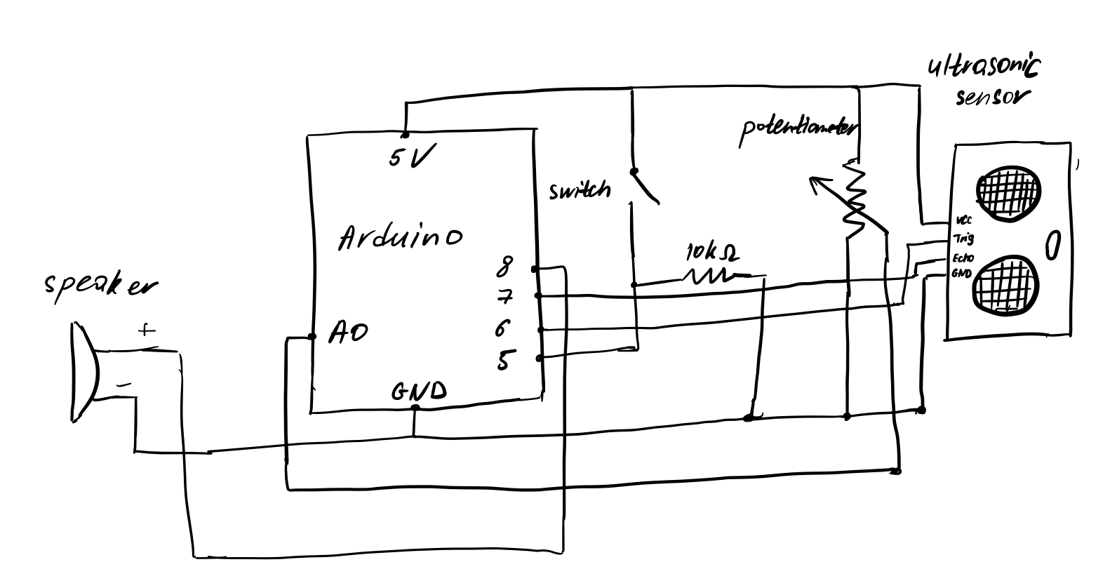
Circuit diagram
Circuit for the music instrument.
Code
// Pin positions.
const int potPin = A0;
const int buttonPin = 5;
const int trigPin = 6;
const int echoPin = 7;
const int speakerPin = 8;

// Other constants.
const int minDistance = 0;
const int maxDistance = 20;

const int toneDurationMin = 30;
const int toneDurationMax = 500;

const float toneDelayFactor = 1.3f;

void setup() {
  pinMode(potPin, INPUT);
  pinMode(buttonPin, INPUT);
  pinMode(trigPin, OUTPUT);
  pinMode(echoPin, INPUT);
  pinMode(speakerPin, OUTPUT);
}

long getSensorDistance() {
  // Send pulse.
  digitalWrite(trigPin, LOW);
  delayMicroseconds(2);
  digitalWrite(trigPin, HIGH);
  delayMicroseconds(10);
  digitalWrite(trigPin, LOW);
  // Read pulse duration.
  long duration = pulseIn(echoPin, HIGH);
  // Calculate distance from duration.
  long distance = (double)duration * 0.034 / 2.0;

  return distance;
}

void loop() {
  // Get distance and constrain it.
  long distance = getSensorDistance();
  distance = constrain(distance, minDistance, maxDistance);

  // Map distance to tone frequency.
  int toneFreqMin, toneFreqMax;
  int buttonState = digitalRead(buttonPin);

  if (buttonState == LOW) {
    toneFreqMin = 20;
    toneFreqMax = 400;
  } else {
    toneFreqMin = 300;
    toneFreqMax = 1500;
  }

  int toneFrequency = map(distance, minDistance, maxDistance, toneFreqMin, toneFreqMax);

  // Calculate time to play the tone based on the potentiometer position.
  int potPosition = analogRead(potPin);
  int toneDuration = map(potPosition, 0, 1023, toneDurationMin, toneDurationMax);

  // Play the tone, then wait some time.
  int waitTime = toneDuration * toneDelayFactor;
  tone(speakerPin, toneFrequency, toneDuration);
  delay(waitTime);
}
Reflection
It was challenging to figure out how the ultrasonic distance sensor worked, because it has 4 pins to set up. We also had to do some math, using the speed of sound, to convert the duration produced by the sensor into a proper distance.
Also, it took a lot of work to figure out the proper ranges for the minimum and maximum frequency for the instrument to play. Too high frequencies were irritating.
One way to improve the instrument is to think about ways to make it easier to use (more accessible). Right now it is a bit awkward to control the potentiometer and button with one hand, while using the other hand with the sensor. Also, it would be convenient to have a way to mute the speaker, or even control its volume.
This project is a simulation of human thirst. We have two LED lights:
– A blue light, which indicates how ‘full’ of water we are. In the code, our ‘fullness’ is represented by the variable ‘capacity’. The lower the capacity, the thirstier we are. The blue light’s brightness indicates our capacity.
– A red light, which is a warning light. When our capacity goes below a threshold, the red light blinks, as a warning that we’re thirsty.
Moreover, we have two inputs:
– A push button. Clicking it refills our capacity to maximum.
– A photosensor. When we cover the photosensor with our hand, the capacity goes down faster, which is similar to how physical activity (e.g. exercise) makes us thirstier faster.
Video demonstration
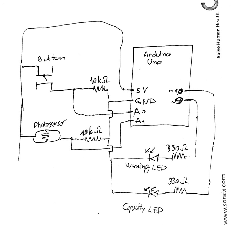
Circuit
The circuit.
Code
Because the code is pretty long, you can find the whole thing here.
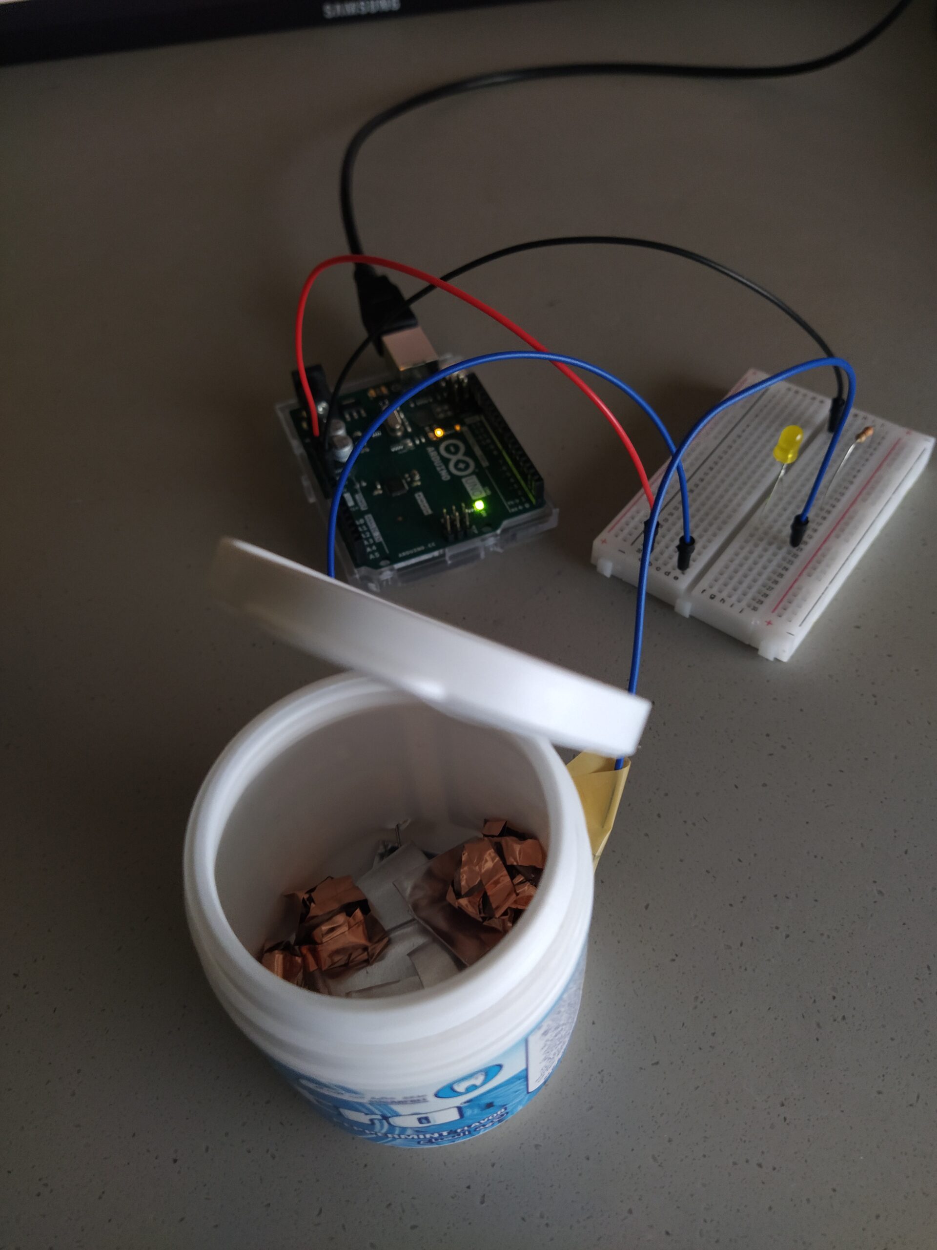
I decided to create a ‘black-box’ type switch. The switch consists of two jumper cables which are connected to the insides of a small box. The box is filled with a few metal sheets and balls of copper tape — essentially a few separate pieces of conductive material.
The switch is initially open. It can be closed by shaking or moving around the box. This causes the contents of the box to move around chaotically. With enough movement, they will connect in such a way that the current from one jumper cable can move to the other one, closing the switch and completing the circuit.
However, by deliberate design, the switch is difficult to control. It isn’t easy to close it immediately, or open it afterwards. Also, often, while moving around the box, it closes for only a brief moment, sending a short signal but then stopping. This creates a kind of controlled chaos and I can imagine using it to create interesting effects using Arduino in the future.
Finally, although the switch can be used most easily with hands, it works with any parts of your limbs, as long as you can move the box.
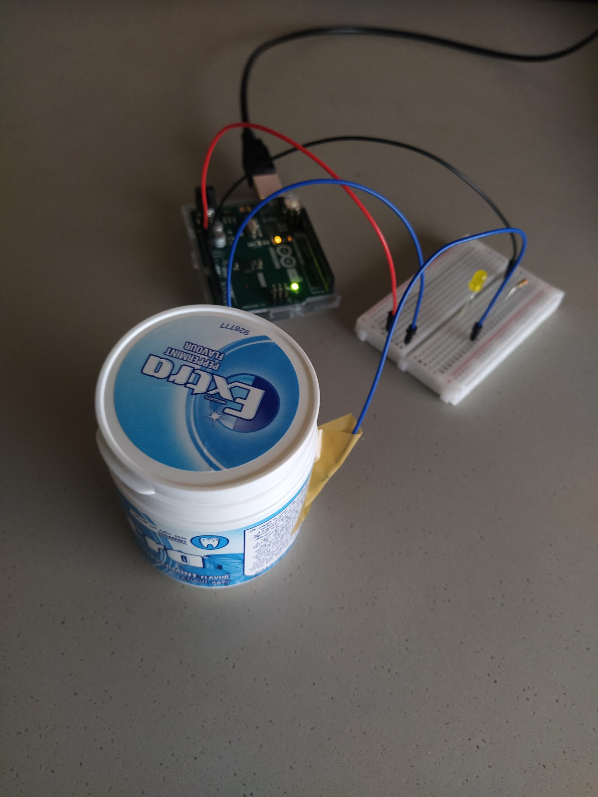
Pictures and video demo
I created a simple circuit to test that the switch works. It looks like this: Arduino 5 Volts -> first jumper cable -> box -> second jumper cable -> LED light -> 300 Ohm resistor -> Arduino ground. The LED light turns on when the switch is closed.
How the switch looks like from the outside.The contents of the box.
It’s highly recommended to play it through once or twice before reading onwards.
Concept
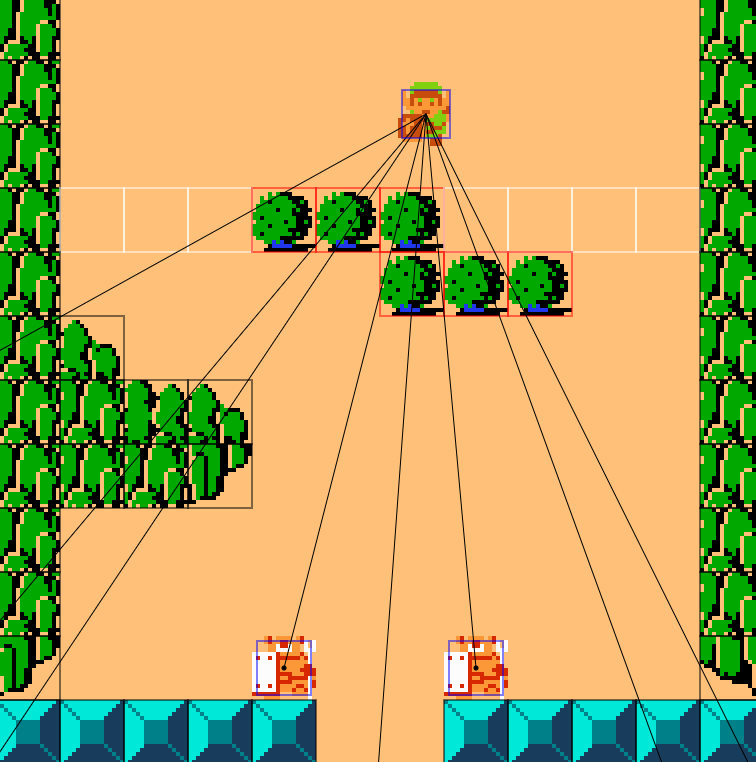
I wanted to create a short retro game inspired by the original The Legend of Zelda game. Simultaneously I wanted to make the player question what it means to attack and kill digital characters in a game. In the majority of games, the player has to or can choose to kill other characters or enemies in the game, and these deaths are very simple, in that the killed character disappears or stops moving, after which the player can completely forget about them forever. My game is a subversion of that.
The game is intended to be played through in two main ways: without killing anyone, or by killing everyone. In order to not kill anyone, the player can try to lure the enemies and run around them. Also, the dash mechanic (activated by pressing E) should make this easier. In order to kill everyone, the player has to attack them with their sword. After the death, a few things happen which can be described as unsettling: the screen flashes in black and white for a second, the music tones down in pitch, a pool of blood appears where the enemy died, and a ghost of the enemy starts following the player. These things are meant to encourage the player to continue playing in one of two ways: either avoiding to kill any future enemies, or killing everything, pushed by their curiosity of what would happen next.
Also, the ending screen changes depending on how many kills the player has, and subtly encourages the player to do another play-through.
High-level project overview
The project uses the Entity-Component system to structure things in a way that allows easily adding new features and content. My GameEngine class manages several “scenes”, with one currently active scene at any moment. At game start, the Menu scene is active, which just shows the title screen and waits for user input to start the game. Afterwards there is a Play scene which loads the level and plays it. Finally, once the level is completed, an End scene shows the end screen and allows going back to the menu.
At each frame, the GameEngines’s update function is called, which calls the currently active scene’s update function, and then draws things to the screen.
Here we can see the main concepts of the Entity-Component system. The logic of the game is divided into several “systems”, which are just functions that do all the work.
What does Entity mean? I do not create separate classes for each different “thing” in the game. In other words, there is no Player class, Enemy class, Tile class, etc. Instead, I have a generic Entity class:
class ComponentList {
  // A list of components that every entity can have, although they can be null.
  constructor() {
    this.animation = null;
    this.transform = null;
    this.bbox = null;
    this.input = null;
    this.state = null;
    this.lifespan = null;
    this.followPlayer = null;
    this.patrol = null;
    this.health = null;
    this.damage = null;
    this.invincibility = null;
    this.keys = null;
    this.owner = null;
    this.message = null;
    this.trigger = null;
  }
}
To each entity, I add components as I see fit, and the systems above handle things based on which components an entity has. For example: everything that I plan to draw to the screen (the player, enemies, tiles) has an Animation component, which is explained in my Midterm progress blog post. Everything that will have a position, velocity, etc., will have a transform component. Everything that will interact with other things (i.e. collision) will have a bounding box component. Everything that is supposed to have health has a Health component. Everything that is supposed to do damage has a Damage component. And so on.
I’m really happy with my decision to structure things in this way, because after I set things up, it was very straightforward to make changes and add new content. However, this was one of the biggest challenges of the project, and it took a long time to implement.
Another big challenging part for me included figuring out how to create, save, and load the level, which led to me to creating a python script which probably saved me several hours of menial work.
Another thing I’m happy about are the effects that happen when an enemy is killed. I experimented with various ways to manipulate the pixels on the screen. I turn the screen to black and white immediately after an enemy’s death. I also wanted to add a greyscale/desaturation effect which increases in intensity as more enemies are killed, and it looked really good, but unfortunately Javascript is very slow and the game became unplayable, even by just scanning the pixels array from p5 once a frame. In terms of sound, after a kill, the pitch goes up for a second, and then goes down to lower than before.
Bonus screenshots
Room 2, normal view.Room 2, debug view. Collision boxes and enemy line of sight are visible.
To enable debug view, uncomment the line:
else if (key == "c") this.drawCollision = !this.drawCollision;
And press “c” while in-game.
Reflection
Areas of improvement include the content of the level and the unsettling/horror effects. Details of the level can be improved, such as adding more rooms, more enemy types, more decorations, and so on. The more this looks like a real game, the better the delivery of the second, hidden part of it. Also, many more horror effects can be added. Although outside of the scope of this project, one could add a hidden final boss or obstacle that only appears if the player has chosen to kill all enemies they encounter. This could further distinguish and solidify the two routes the game is intended to be played through.
For my midterm project, I want to create a philosophical experience disguised as a dungeon crawler game. I am taking inspiration from The Legend of Zelda, to the point that I plan to use their assets. The experience will consist of two parts:
Start of the game, which looks like something you’d find in old retro games from the 90s. You’re shown that you can move around and attack, and there are monsters aroud, so you conclude that you should attack and kill them.
Eventually, you have to be killed by the monsters (a scripted death). Then the tone (and possibly artwork, art style) completely changes. You’re presented with a ‘path’ to the afterlive and by walking the path you have to confront all the lives you took. I essentially want to subvert the expectations of what it means to be a character in a retro video game killing other live in the game.
From the start, I realized that one of the most difficult parts would be creating a good and efficient animation system, where I would be able to animate entities in the game using sprites/spritesheets. Therefore this is the first major thing I implemented. This actually consisted of two major things: 1) a mechanism for loading assets (images, sounds, etc.), and 2) a way to animate game entities.
Loading assets
I wanted to make my mechanism for loading assets easily configurable, so that I could easily change and configure images, spritesheets, and animations without going through several places in the code. I came up with the concept of having a file, such as assets.txt, which contains all my assets. Each line in the file would look like one of the following:
(Note: I plan to add a way to define sounds too. And I will explain how animations work in a bit.)
I am essentially giving a name to all assets so I can reuse and easily find them later when creating the game entities. At the same place I am configuring them.
In practice, the concept of having a file that tells you which other files to load (i.e. images) seems difficult to implement in p5, even using the preload function. Therefore I had to define the ‘assets’ file as a list of strings, which is functionally the same, although looks a bit uglier. Still, it accomplished what I wanted.
Moving on. I created an Assets class which handles the loading of all asset files and creating all animations, and I do these things in the preload function of p5. In the assets class, I have two maps, which I populate using information from the file:
textureName (a string) –> p5.Image (the thing created when using loadImage)
animationName (a string) –> Animation (a class I created and will describe soon)
When loading assets, I had to make sure that all textures are loaded before all animations, because every animation object has a texture which is passed to its constructor and whose properties are used immediately. To accomplish this order of loading, I had to use callback functions, but everything turned out alright in the end.
Animations
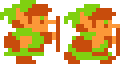
I created an Animation class which contains its name, its spritesheet (texture, i.e. a p5.Image), how many frames the animation should have before ending or repeating, and its speed (how often it should update). For example, a texture I used is the following:
run_right.png
Then I create an animation that uses this texture (i.e. this texture is the animation’s spritesheet). The animation has a frameCount of 2 and a speed of 15, which means that it should change its state every 15 frames.
To draw animations I used p5’s feature to only draw sections of its spritesheet. I also store at which ‘cell’ I currently am in the animation in order to speed things up a bit.
Switching between animations based on state
I wanted my player character to use a different animation depending on whether they are standing, running, attacking, etc. To implement this I also store a state component in the player, which is just a string with one of these values: “stand”, “run”, or “attack”. I also store the direction the player is facing along each axis, which changes when they move. For example, if they are currently facing down, the facing would be a vector (0, 1). Facing up: (0, -1). Facing right: (1, 0). Facing left: (-1, 0). Using this, every frame, I update the animation to display.
The sketch
Future plans
With the asset and animation systems done, it is now very easy to add and use new textures and animations. I can now focus on creating the level, adding sounds/music, and most importantly creating the second component of the game.
I wanted to do a data visualisation that would show the world in an interesting way. Since I’ve been working on a project which created a dataset of two million notable people in history, I decided to use that dataset. Since this dataset is huge (the whole .csv file is 1 GB), I decided to filter it so that I only look at people in Europe with a notability index as defined in the paper of 23.5 or more. This led to a dataset with 52000 observations and a file size of 4.3 MB.
Each observation (row) in the dataset, after filtering and selecting only the columns I wanted to use, has the birth year, birth location and death location (latitude and longitude) of a notable person in history, as defined by the paper. Therefore I decided to make my visualisation a timeline, from 3500 BC to 2020 AD, where for every year I draw the birth and death locations of all people born at that year. Moreover, the more notable the person as defined by their notability index, the bigger their circle would be. I draw the people as translucent circles, so that if many people were born near the same location, the colors will add up. I picked the color green to represent a birth location, and red to represent a death location.
Code highlight
I’m particularly proud of the part of my code that converts a person’s latitude and longitude into (x, y) coordinates which I use to draw the person later. Latitude and longitude are coordinates on a sphere, while x and y are coordinates on a two-dimensional plane. I essentially needed to figure out a map projection. There are many of these, such as the Mercator projection, Robinson projection, etc. However, I managed to find a projection for which the code is incredibly simple: the Equirectangular projection. This formula is very simple: we map latitudeto x and longitude to y. However, this produces a map rotated 90 degrees clockwise, so we also rotate it by using a bit of linear algebra.
function getCoordsFromLatLon(lat, lon) {
  // Equi-rectangular projection.
  // Formula from:
  // https://www.marksmath.org/classes/common/MapProjection.pdf
  // (lat, lon) -> (x, y)
  // But we also rotate 90 degrees:
  // (x, y) -> (y, -x)
  return {x: lat, y: -lon};
}
Note that changing this mapping function will result in different interesting visualizations.
Reflection
The final visualization looks good, especially after tuning a few of the parameters, such as the colors, radii, and transparency of the circles. The dataset I used is huge and has many parameters besides the ones I used. For example, instead of coloring circles based on the person’s birth and death, we can instead use data such as a person’s occupation (discovery/science, culture, leadership, sports/games, other), which might show interesting effects over different locations. Finally, we can can even create a 3D visualization where we place the points on an actual sphere that we might move around. However, the slow performance of p5.js might make this difficult with more than a few thousand data points.
“The Satanic Donut” is a donut that tries to, but can never completely finish creating itself. One way to interpret it is as a display of never-ending conflict, due to its rapidly-moving and constantly-at-odds components of red and black colour.
As classes allow us to create objects where each object can have its own unique behaviour, I got the idea to create an art piece where the entities inside the art piece are the ones creating the art. Therefore, I conceptualised two groups of entities inside my art: ‘leaders’ and ‘followers’. The leaders move around, while the followers follow the leaders. All entities leave a trail of colour as they move around, as if there are many small brushes simultaneously creating the art piece.
The catch is, the leaders never stop moving towards their cryptic destination, while the followers never stop going after them. Thus, the art piece can never truly finish drawing itself.
Code highlight
A particularly interesting part of the code is the logic that enables each follower to ‘steer’ towards a leader. The followers don’t instantly turn in the direction of their target, but instead perform a smooth turn.
steerTowardsTarget() {
  // Update velocity to point towards the target.
  // However, use a 'steering' effect so the follower does not instantly turn
  // towards the target, but instead gradually turns.
  if (this.target == null) {
    return;
  }

  // v here is a vector pointing towards the target, with its magnitude being
  // how far we have to move.
  let v = this.target.pos.copy();
  v.sub(this.pos);

  if (v.mag() <= this.speed) {
    // We have reached the target.
    this.velocity = v.copy();
  } else {
    // Make v have a magnitude of our speed.
    // It is still pointing towards the target.
    v.normalize();
    v.mult(this.speed);
    // Make v be the vector from the tip of our current velocity
    // to the tip of the vector pointing towards the target.
    v.sub(this.velocity);
    // Multiply v by a constant to make its effect less pronounced.
    v.mult(STEERING_CONSTANT);
    // Add v to our velocity, to partially change velocity towards our target.
    this.velocity.add(v);
  }
}
The explanation for how this works requires a bit of math knowledge, but this video explains it very well, starting from 50:27. This is where I found out about this concept.
Reflection
The concept of an art piece drawing itself using several small brushes is very interesting and is worth exploring more deeply. Namely, one could devise many different classes of entities, each of which moves in its own unique way or pattern. With every small modification, just running the simulation could create something you never expect.
My art piece is a collection of white lines and squares on a black background. The lines and squares move around erratically. It was inspired by the movement of molecules in real life: quick, erratic, random.
Code highlight
I’d like to highlight my draw function.
function draw() {
  background(0, 0, 0, 130);

  // Update movers and draw them.
  for (let mover of movers) {
    // Add a line to the end of the mover.
    addLine(mover);

    // If the mover has more lines than allowed, remove the first line.
    if (mover.length > MOVER_LINE_COUNT) {
      removeLine(mover);
    }

    // Draw all lines.
    for (let l of mover) {
      line(l[0], l[1], l[2], l[3]);
    }
  }

  // Update squares and draw them.
  for (let square of squares) {
    moveSquare(square);
    rect(square[0], square[1], square[2], square[2]);
  }
}
Although the overall logic of my code is the most complex thing I’ve written so far in this course, the draw function, where everything actually happens, is very simple and straightforward. This is because I used functions (e.g. addLine, removeLine, moveSquare) to isolate unrelated, functional pieces of code.
The sketch
Reflection
I’m fairly happy with the final sketch. I went for minimalism and an old school digital style, so I only used black and white colors. Potential additions can be more shapes, for example circles or triangles. Another interesting addition could be to implement a simple physics system, with collision detection. This way, one could make the shapes bounce off each other.
My self-portrait is a sort of digital avatar of myself. It is not overly realistic, but not overly abstract either. For example, my head is oval-shaped, and my eyes, eyebrows, nose, and mouth are in the approximately correct positions. However, going with a simplistic style, I opted to make the my torso triangular, and decided to not add ears. Moreover, I did not add my hair, but instead put on my favourite beanie-shaped hat. The colours black and grey are prominent, as they are some of my favourite.
As I was creating the self-portrait, I realised that there was an opportunity to make everything more interesting by making myself a kind of android, with laser eyes. Therefore I made my eyes a red colour which changes intensity over time, and I also added green lasers which follow the user’s mouse. Therefore my portrait can be said to represent the slightly grumpy and almost penetrating stare of someone who really needs their coffee in the morning, or a college student who is in their fourth class of the day.
Code highlight
I am particularly proud of the part of the code that creates the lasers, as well as their fading effect. At the start of each frame, instead of setting the background to a solid black colour, I set it to black with an alpha of 10 (out of total 255). This means that with every frame, the previously drawn lasers are not completely erased, but slowly fade out.
background(0, 0, 0, 10);
To make the code cleaner and more principled, I store the coordinates of my eyes in two arrays, where the first two numbers represent the (x, y) coordinates of the top left corner of the eye, and the next two represent the coordinates of the top right corner of the eye.
Note that, in my code, each coordinate is a number between 0 and 1, and is multiplied by the height or width of the canvas when drawing.
Then, I draw the eye, before finally drawing the lasers. The width of the lasers follows a sine curve that moves between 0 and 2.
strokeWeight(sin(frameCount * 0.01) + 2);
Again, to make the code cleaner and more principled, I define a function that, given the coordinates of an eye, returns its center, but slightly moved in the x and/or y direction, to create a ‘fuzz’ effect. I then use the function to get the center of each eye.
Finally, I draw the lasers. Each laser is a line from an eye to the mouse; however, the mouse coordinates are also slightly shifted in the x and/or y direction, to emphasize the ‘fuzz’ effect.
I am fairly happy with my final sketch. Many more visual details may be added to increase the realism and/or the digital-like effect. For example, if I decided to lean more into the android aesthetic, I could make my skin a metal-like texture instead of just grey, and add robotic details to my hat and/or clothes. In terms of interaction, to emphasize that the person in the sketch is ‘watching’ you, I can make them ‘lean’ towards the mouse as well, in addition to the lasers.