Final Project: A Work Accompaniment

In summary, my final project was a series of failed experiments.

My original goal was to use the p5.speech library to create something for Zoom classes. The user would be alerted every few minutes if they ended up falling asleep on their pillow using a capacitative touch sensor. I also hoped to record the transcript of the meeting/class in session and play some sort of alarm if the user’s name was said, urging them to get up.

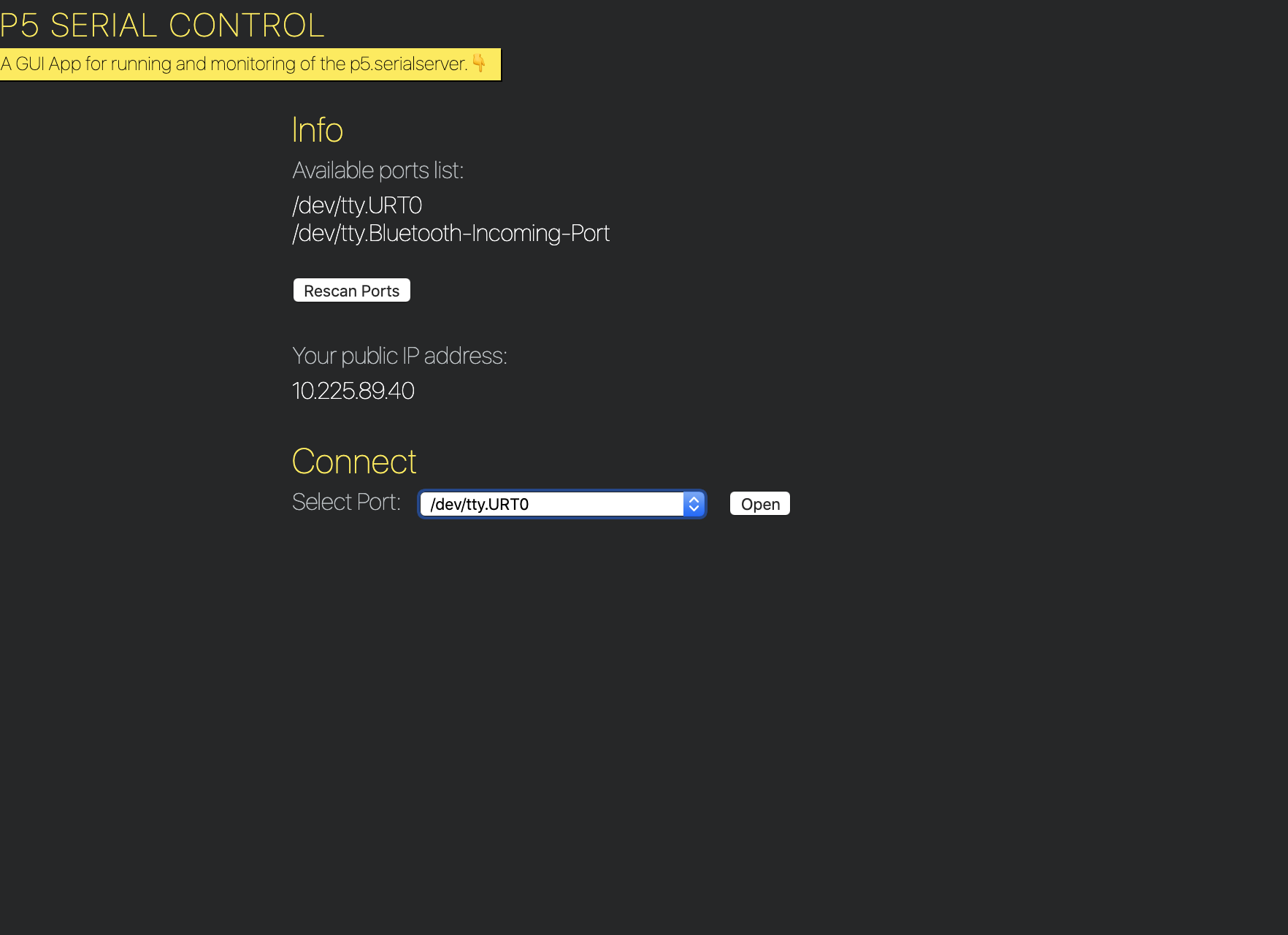
I ended up playing around with this idea, using the p5.serialcontrol program to communicate between p5.js and Arduino. While it is cool that this exists, it was a bit clunky in terms of workflow in terms of connecting ports, etc. Additionally, I wasn’t fully comfortable using the p5.speech library to record transcripts. Other than the technical problem of pipes breaking, I didn’t think it was okay to record the transcripts due to user privacy. Additionally, the speech recognition was a bit better than expected but probably still only a 65% recognition of the names of friends I tried, so I thought it would still make microaggressions in its failure to understand certain friends’ names, etc.

p5.serialcontrol gui app screenshot
Screenshot of p5.serialcontrol app

Thus, I needed to repivot my idea. I really wanted to keep the capacitative touch element of the project because this was something I had never been exposed to. I decided to maintain the original spirit of the project as well…something that could help me personally. I have lots of low energy periods due to insomnia and perpetual migraines, but I still have to do my best to complete my work. However, amidst the low energy, I need to make sure I don’t completely fall asleep. It’s not very predictable so setting an alarm ahead of time is not something I would know to do. Thus, I thought the capacitative touch sensor could be useful to see if I do end up falling asleep–having a sensor in my pillow could detect this and set into motion a way to wake me up.

From there I imagined having a combination of vibrations and sound to wake me up. I originally considered using an LED to show whether the sensor was working, but thought bright lights and migraines aren’t the greatest of combinations. In our class check-in, Aaron suggested using motors to create the vibrations.

sketch of program
Sketch of Program

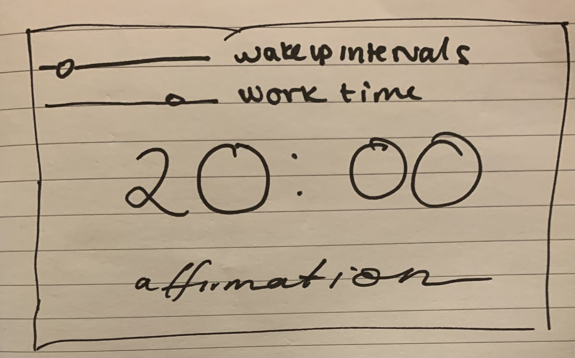
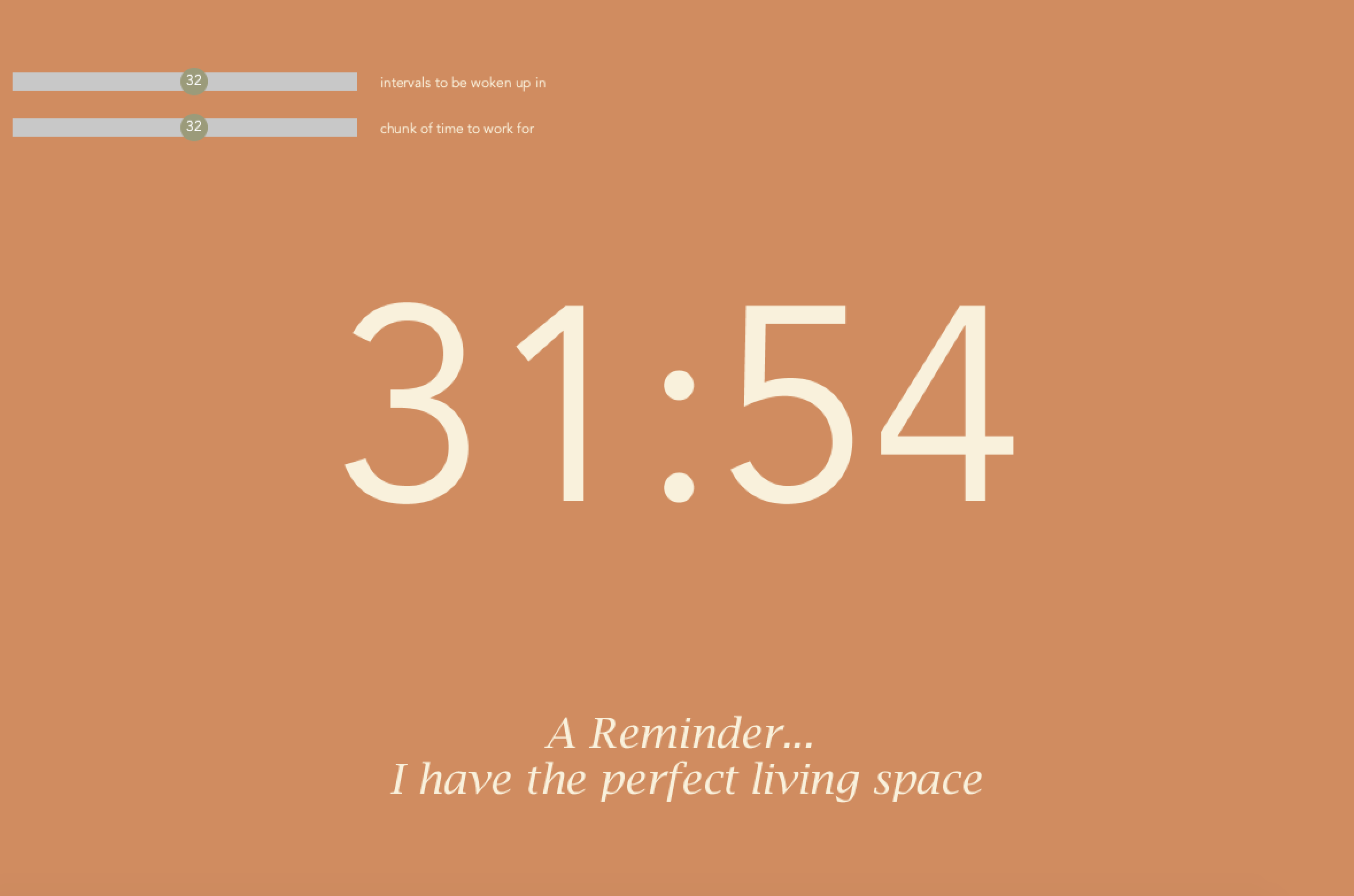
I was also trying to brainstorm what the Processing program could look like.  Having structured work time and making sure I take breaks is important to make sure I don’t get too fatigued. Thus, I thought it could be interesting to make my own version of the Pomodoro method. Additionally, doing work tends to bring out a lot of negative thought patterns, so I wanted to integrate some positive energy into the program. I found this affirmation API that I could pull a random message from.

Creating the scrollbars was a bit manual, but I had help from the Scrollbar Processing documentation example. I modified it to make more simple and more to the aesthetic of the program and used a map function instead of calculating the ratio of the slider’s position to the slider’s width. I also added text to know what the current value of the slider is.

I designed a color palette using Coolors and tested it for accessibility for various visual abilities using their tool.

Creating the stopwatch display was a bit tricky because I wanted the new time to appear any time the scrollbar was moved. I ended up creating a helper function to calculate the new timer value. This would be used in the calculateTime function. Another issue I had was displaying the time in a way easy for the reader to understand. For instance, simply using the numerical value of minutes and seconds wouldn’t work for the 60 second mark (the user would expect to see 00 instead of 60) and for the second ticks less than 10 (the user would expect to see :01 instead of :1). I ended up just using an if statement to check for these edge cases, but I’m sure there is a smarter way to do this.

The final aspect of the front page of the program was the affirmations. Using the http.requests library was pretty straightforward, but the response was not in a form conducive for using JSON. I ended up just creating a substring of what was returned to include only the actual message part.

prototype of home screen of program with stopwatch, scrollbars, and affirmation at the bottom
I kind of don’t vibe with some of the affirmations in the API but here’s a home screen of the program

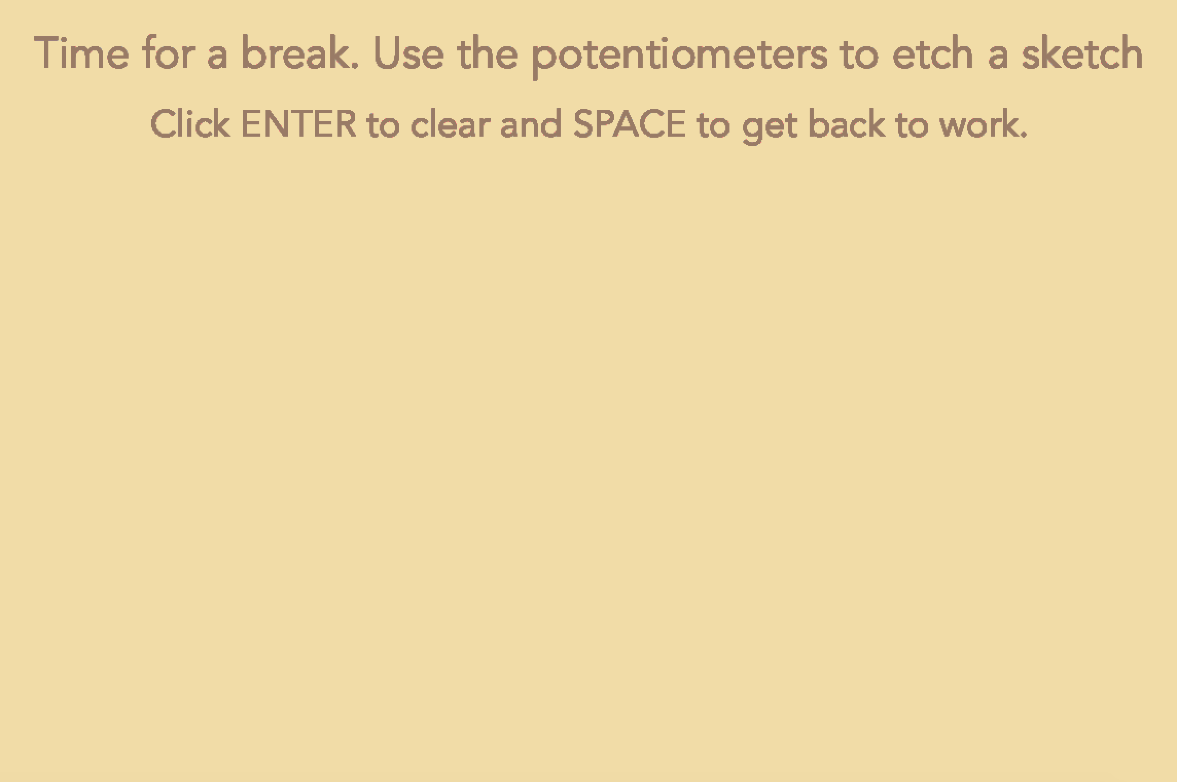
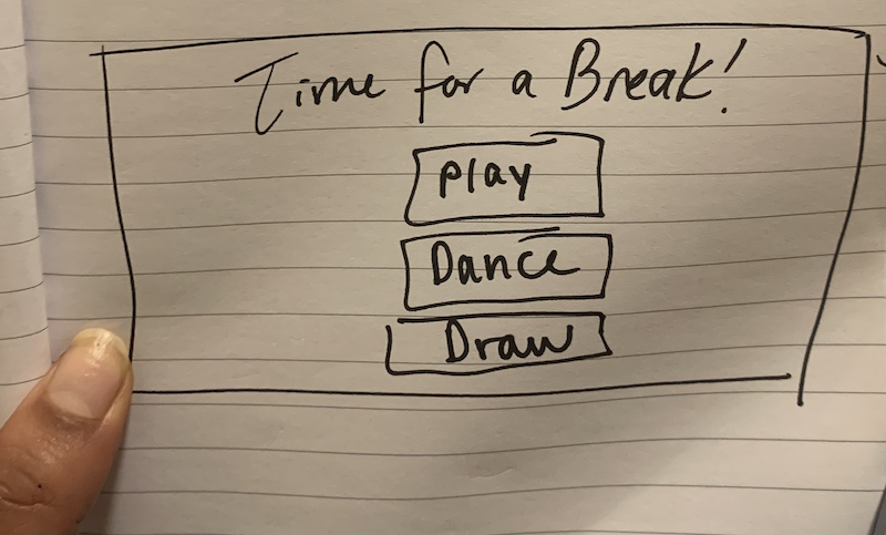
I also wanted to include another element of interaction with the Arduino. Thus, I thought I could create something for the break period of the program that involved using a hardware component. I considered doing a dance break–playing music with dancing LEDs, but had done something similar for one of the weekly projects and wanted to learn something new. I also thought it could be interesting to do a small mini game using the buttons on Arduino as controls, but I’m a bit tired of making games in all honesty. Thus, I decided to do something involving drawing. From the moment we starting working with potentiometers, they reminded me of the little knobs on those toys Etch-a-Sketch–I decided to build a mini Etch-a-sketch for the break part of the program!

prototype of drawing game
Screen to etch a sketch for break part of program

In terms of my hardware, I used the capacitative touch sensor. I was inspired by the Love You Pillow project on the Arduino Hub to use foil for the sensor. I had to experiment a bit with finding the right threshold, but overall, it worked pretty smoothly and consistently.  I used the motor shield to connect two motors to create the vibrations…the code and wiring was heavily remixed from the class we spent on motors. I also used a piezo buzzer and two potentiometers.

Component Setup: breadboards with foil in pillow as sensor
Overview of Component Setup
Closeup of Wiring
Closeup of Wiring

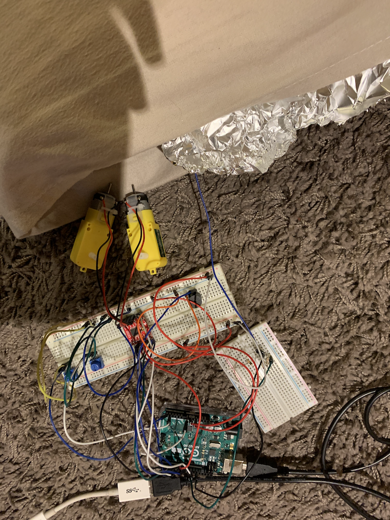
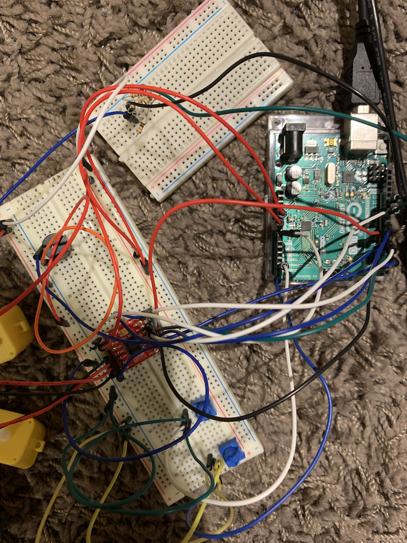
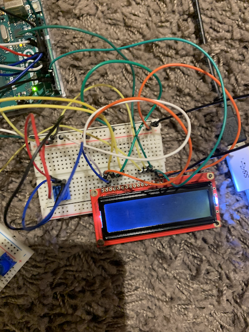
I also experimented a bit with the LED display–I was thinking of randomly sending messages like “Hydrate” and “Stretch,” but I ran out of pins to include it in the final setup, already using some of the analog pins as digital pins.

LCD Display setup
LCD Display Setup

Overall, I’m not very content with the project. I know I’m capable of better work, but for where I’m at in terms of energy, I think I did my best. There’s definitely a lot of room for improvement. It could be cool to include the LCD Display with user choice of messages on the Processing screen (hydrate, eye break, stretch, breathe deeply). It could be cool to have more options for what to do on the break. I realize I don’t really like drawing with the etch a sketch, so it could be more useful to explore other potential activities like making a mini piano or game, etc. I think the user interface of the etch a sketch could be made more interesting by having more user input in choosing a color etc.

sketch of potential choice of break

Here’s a walkthrough of my project:

CODE:

Arduino:

#include <CapacitiveSensor.h>
#include <SparkFun_TB6612.h>
//#include <LiquidCrystal.h>      

#define AIN1 2
#define BIN1 7
#define AIN2 4
#define BIN2 8
#define PWMA 5
#define PWMB 6
#define STBY 9

 
//LiquidCrystal lcd(19, 18, 17, 16,11, 3);   
// these constants are used to allow you to make your motor configuration 
// line up with function names like forward.  Value can be 1 or -1
//from motor library example code
const int offsetA = 1;
const int offsetB = 1;
int duration = 2000;
Motor motor1 = Motor(AIN1, AIN2, PWMA, offsetA, STBY);
Motor motor2 = Motor(BIN1, BIN2, PWMB, offsetB, STBY);
//pressed boolean indicates whether the pillow sensor senses touch
int pressed = 0;
long timer;
//threshold for pillow sensor; if greater than threshold, there is touch
int threshold = 30;
//timeLength variable from first scrollbar in Processing program
int timeLength;

CapacitiveSensor   cs_4_2 = CapacitiveSensor(10,12);        //12 is sensor pin
//count indicates what level of intensity to be woken up
int count = 0;
int piezoPin = 3;

int pot1 = A4;
int pot2 = A5;

void setup()                    
{
   cs_4_2.set_CS_AutocaL_Millis(0xFFFFFFFF);     //from capacitive sensor library
   Serial.begin(9600);
   Serial.println(0,0);

//   lcd.begin(16, 2);                 //tell the lcd library that we are using a display that is 16 characters wide and 2 characters high
//  lcd.clear();                      //clear the display
}

void loop()  {
 while (Serial.available()) {
  //read from Processing
  timeLength = Serial.parseInt();
  //turns into minutes, change this value if you want the interval in seconds
  timeLength *= 60000;

   if (Serial.read() == '\n') {
    //sends potentiometer values to processing
  int val1 = analogRead(pot1);
  Serial.print(val1);
  Serial.print(",");
  int val2 = analogRead(pot2);
 
  Serial.println(val2);
   }  
  }

//   lcd.setCursor(0, 1);              
//  lcd.print(timeLength);
//  
    long start = millis();
    long cap =  cs_4_2.capacitiveSensor(30);
    //if the sensor value is greater than the threshold and has not yet been activated
    //starts sensor and level count
    if (cap > threshold && pressed != 1){
      pressed = 1;
      timer = millis();
      count = 0;

    } else if (cap > threshold && pressed == 1) {
      pressed = 1;
      //if sensor value is less than threshold, turn pressed off
    } else if (cap < threshold && pressed == 1) {
      pressed = 0;
    }
  if (pressed == 1) {
//   lcd.setCursor(0, 0);              
//  lcd.print("sensor on");
//  lcd.setCursor(0, 1);              
//  lcd.print(timeLength);

//after every X minutes
  if (millis() - timer >= timeLength) {
    timer = millis();
   level(count);
   count += 1;
  }
  }  
}
//function creates intensity of response to wake up depending on level
void level(int count) {
  switch(count){
  case 0:
    vibrate(0);
    break;
  case 1:
    vibrate(1);
    break;
  case 2:
    vibrate(2);
    break;
  case 3:
    vibrate(2);
    tone(piezoPin, 200, duration);
    break;
  default:
    vibrate(3);
    tone(piezoPin, 500, duration);
    break;
  }
}
//vibrate function to determine speed based on level
void vibrate(int level) {
  int sp = 0;
  if (level == 0) {
    sp = 75;
  } else if (level == 1) {
    sp = 120;
  } else if (level == 2) {
    sp = 180;
  } else {
  
    sp = 255;
  }
  //moves the motors
  motor1.drive(sp,duration);
  motor2.drive(sp,duration);
  //stops motors
  motor1.brake();
  motor2.brake();
}

Processing:

import http.requests.*;
import processing.serial.*;

Serial myPort;

Scrollbar bar1;
Scrollbar bar2;

int first = 0;
int second = 0;
float lastX = 0;
float lastY = 0;
//Button play;
//Button dance;
//Button draw;

int seconds;
int minutes;

int timer;
int startTime;

PFont lucida;
PFont avenir;
int state = 0;
String response;
void setup() {
    size(1200, 800);
    lucida = createFont("Lucida Bright Italic", 36);
    avenir = createFont("Avenir", 12);
    textAlign(CENTER);
    background(#D08C60);
    //requests affirmation from api
    GetRequest affirm = new GetRequest("https://dulce-affirmations-api.herokuapp.com/affirmation");
    affirm.send();
    response = affirm.getContent();
    //finds string of affirmation
    response = response.substring(12, response.length() - 3);
    
    //Scrollbar(x, y, width, height, min val, max val)
    bar1 = new Scrollbar(20, height/10, 300, 16, 1, 60);
    bar2 = new Scrollbar(20, height/10 + 40, 300, 16, 1, 60);
    //finds initial time of scrollbars
    adjustTime();
    
     //play = new Button("PLAY", width/2 - 150, height/3, 300, 80, 2);
     //dance = new Button("DANCE", width/2 - 150, height/3 + 120, 300, 80, 3);
     //draw = new Button("DRAW", width/2 - 150, height/3 + 240, 300, 80, 4);
     
     //sets up serial communication
     String portname=Serial.list()[2];
      myPort = new Serial(this,portname,9600);
      myPort.clear();
      myPort.bufferUntil('\n');
      delay(1000);

}

void draw(){
//if home screen
  if (state == 0) {
    background(#D08C60);
    //scrollbars - draw and update if user input
    bar1.update();
    bar2.update();
    bar1.display();
    bar2.display();
    fill(#F9F1DC);
    //displays affirmation
    textFont(lucida);
      text("A Reminder...", width/2, height - 140);
      text(response, width/2, height - 100);
    textAlign(LEFT);  
    textFont(avenir);
    text("intervals to be woken up in", 340, height/10 + 5);
    text("chunk of time to work for", 340, height/10 + 45);
    //calculates and displays time
    calculateTime();
  //} else if (state == 1) {
  //    background(#F1DCA7);
  //    textFont(avenir);
  //    textSize(72);
  //    fill(#997B66);
  //    text("Time for a break!", width/2, height/8);
  //    play.display();
  //    dance.display();
  //    draw.display();
  //    play.update();
  //    dance.update();
  //    draw.update();
  } else if (state == 2) {
    //drawing screen game
      textFont(avenir);
      textSize(42);
      fill(#997B66);
      text("Time for a break. Use the potentiometers to etch a sketch", width/2, height/8);
      textSize(36);
      text("Click ENTER to clear and SPACE to get back to work.", width/2, height/8 + 65);
      //maps potentiometer value to some coordinate on the screen
      float x = map(first, 0, 1023, 0, width);
      float y = map(second, 0, 1023, height/4, height);
      //finds random color for the line
      stroke(random(0,255), random(0,255), random(0,255));
      //idea for saving last coordinate from this project: http://graysonearle.com/edu/physcom/etch-a-sketch-arduino-processing/
      line(x, y, lastX, lastY);
      lastX = x;
      lastY = y;
  } 
}
//scrollbar class for user input on first screen
class Scrollbar {
  //slider width and height
  int sw;
  int sh;
  float xpos;
  float ypos;
  //the slider position (ellipse)
  float slider_pos;
  float newpos;
  float sliderMin;
  float sliderMax;
  boolean mouseOnTop;
  boolean moved;
  boolean posChanged;
  //min and max values of slider
  int sValMin;
  int sValMax;
  
  Scrollbar(float x, float y, int w, int h, int minVal, int maxVal) {
    sw = w;
    sh = h;
    xpos = x;
    ypos = y - sh/2;
    slider_pos = xpos + sw/2 + sh/2;
    newpos = slider_pos;
    sliderMin = xpos;
    sliderMax = xpos + sw;
    sValMin = minVal;
    sValMax = maxVal;
    posChanged = false;
  }
  
  void update() {
    //if user mouseX, mouseY is on top of the scrollbar
    if (overEvent()) {
      mouseOnTop = true;
    } else {
      mouseOnTop = false;
    }
    //if mouse held and on top, then the scrollbar is being moved
    if (mousePressed && mouseOnTop) {
      moved = true;
    }
    
    if (!mousePressed) {
      moved = false;
    }
    //keep within the range of the slider
    //code remixed from https://processing.org/examples/scrollbar.html
    if (moved) {
      newpos = constrain(mouseX - sh/2, sliderMin, sliderMax);
    }
    //if slider value has changed
    if (abs(newpos - slider_pos) > 1) {
      slider_pos += (newpos -slider_pos);  
      adjustTime();
    }
  }
  
  float constrain(float val, float smin, float smax) {
    return min(max(val, smin), smax);
  }
  boolean overEvent() {
    if (mouseX > xpos && mouseX < xpos + sw && mouseY > ypos && mouseY < ypos + sh) {
      return true;
    } else {
      return false;
    }
  }
  //creates the scrollbar
  void display() {
    noStroke();
    fill(200);
    rect(xpos, ypos, sw,sh);
    fill(#9B9B7A);
    //ellipse is the slider part of the bar
    ellipse(slider_pos, ypos + sh/2, 1.5 *sh, 1.5*sh);
    fill(255);
   textAlign(CENTER);
    textFont(avenir);
    //label of the actual value
    text(getVal(), slider_pos, ypos + sh/1.5);
  }
  
  int getVal() {
    float mapVal = map(slider_pos, xpos, xpos + sw, sValMin, sValMax);
    return int(mapVal);
  }
 
}
//get value from scrollbar and create a new start time
void adjustTime() {
  timer = bar2.getVal();
  startTime = millis();
}

void calculateTime() {
  seconds = 60 - ((millis() - startTime)/1000) % 60;
  minutes = timer - 1 - ((millis() - startTime) / 60000);
  //displays time in middle of screen
  textFont(avenir);
  textSize(240);
  textAlign(CENTER, BOTTOM);
  if (seconds == 60) {
    text(minutes + 1 + ":00", width/2, 2*height /3);
  } else if (seconds < 10) {
  text(minutes + ":0" + seconds, width/2, 2*height /3);
  } else {
    text(minutes + ":" + seconds, width/2, 2*height /3);
  }
  //when timer runs out, move to next screen
  if (seconds == 60 && minutes <= 0) {
    state = 2;
    background(#F1DCA7);
  }
}
//class Button {
//  String msg;
//  int xpos;
//  int ypos;
//  int w;
//  int h;
//  int cntl;
  
//  Button(String words, int x, int y, int w_, int h_, int st) {
//    msg = words;
//    xpos = x;
//    ypos = y;
//    w = w_;
//    h = h_;
//    cntl = st;
//  }
  
//  void display() {
//    noStroke();
//    if (mouseX > xpos && mouseX < xpos + w && mouseY > ypos && mouseY < ypos + h) {
//      fill(#7A6352);
//    } else {
//      fill(#997B66);
//    }
//    rect(xpos, ypos, w, h);
//    textAlign(CENTER, CENTER);
//    fill(#F1DCA7);
//    text(msg, xpos + w/2, ypos + h/3);
//  }
  
//  void update() {
//    //if button is clicked
//    if (mousePressed && mouseX > xpos && mouseX < xpos + w && mouseY > ypos && mouseY < ypos + h) {
//      state = cntl;
//      background(#F1DCA7);
//    }
//  }
//}

void keyPressed() {
  if (state == 2) {
    //returns to home screen if SPACE is clicked
    if (key == ' ') {
      state = 0;
    }
    //refreshes background if ENTER clicked to allow for new drawing
    else if (key == ENTER) {
    background(#F1DCA7); 
    }
  }
}
void serialEvent(Serial myPort){
 String s=myPort.readStringUntil('\n');
 println(s);
  s=trim(s);
  if (s!=null){ 
    //gets value of potentiometer
    int values[]=int(split(s,','));
    first = values[0];
    second = values[1];
  }
  //writes to arduino the scrollbar value
  myPort.write(bar1.getVal() + "\n");
}


Final Project Progress

For my project, I’m building some sort of contraption to accompany Zoom classes. It’s been a chaotic week and I haven’t made as much progress as I would have liked, but I’ve been playing around with the speech recognition library in P5.js.

Here’s my code thus far:

	var myRec = new p5.SpeechRec('en-US', parseResult); // new P5.SpeechRec object
	myRec.continuous = true; // do continuous recognition
	myRec.interimResults = true; // allow partial recognition (faster, less accurate)
var recordedString = "";

	var x, y;
	var dx, dy;

	function setup()
	{
		// graphics stuff:
		createCanvas(800, 600);
		background(255, 255, 255);
		fill(0, 0, 0, 255);
	

		// instructions:
		textSize(20);
		textAlign(LEFT);
		

		//myRec.onResult = parseResult; // now in the constructor
		myRec.start(); // start engine
	}

	function draw()
	{
		text(recordedString, 20,20);
	}

	function parseResult()
	{
			var mostrecentword = myRec.resultString.split(' ').pop();
			recordedString += mostrecentword;

	}

I still need to add the functionality for wrapping the string and making sure that it removes a word printed if it realizes it’s actually a different word. For instance, when saying the word “happening’, “happy” would print to the screen and then “happening.”

This week, I hope to get started on building a capacitor sensor (foil inside pillow).

Final Project Proposal

For my final project, I’m going to build something for this Zoom era. I get a lot of migraines and sometimes just need to put my head down during classes/meetings…but, I don’t want to fall asleep!

This contraption aims to detect when the user has put their head down and gently remind them to stay present. The user also will have the option to display the text of what is being said.

The Arduino program:

Input: when has the user put their head down. I will use either an ultrasonic sensor or use this Capacitor Sensor library to create a sensor using foil inside the pillow.

Output: gentle sound using piezo buzzer depending on input in Processing program, also sends signal to Processing program that user has put head down

(I would also like to explore creating vibrations as output but am not sure how to do this)


The Processing program (p5.js):

Input: signal from Arduino that user has put head down,  speech of class/meeting, time interval user wants to be reminded at

Output: display text of class/meeting, sends signal to Arduino of when to create sound/vibrations


Considerations:

The p5 program will have an alert: the user should only display the transcript if there is consent from the other participants in the Zoom call (ex: meeting is being recorded). The program will also not save the text anywhere and will be cleared from the screen after a certain time.

The P5 speech library I wanted to use (Thanks Aaron for the rec!) seems to be better than expected at recognizing names that aren’t typically used in English (it recognized a lot of my friends’ names and mine when I experimented), but it will definitely not be perfect, so I’m not sure whether to proceed with the name recognition alarm feature.

Exercises: Serial Comms

Exercise 1: I essentially modified the starter code such that the y position remained fixed in the middle of the screen.

Arduino:

int pot = A0;
 
void setup() {
  Serial.begin(9600);
  Serial.println("0");
  pinMode(pot, INPUT);
}
 
void loop() {
  while (Serial.available()) {
    if (Serial.read() == '\n') {
      int sensor = analogRead(A0);
      Serial.println(sensor);
    }
  }
}

Processing:

import processing.serial.*;
Serial myPort;
int xPos=0;
int yPos=height/2;
 
void setup(){
  size(960,720);
  printArray(Serial.list());
  String portname=Serial.list()[1];
  println(portname);
  myPort = new Serial(this,portname,9600);
  myPort.clear();
  myPort.bufferUntil('\n');
}
 
void draw(){
  background(255);
  ellipse(xPos,yPos,30,30);
}
 
void serialEvent(Serial myPort){
  String s=myPort.readStringUntil('\n');
  s=trim(s);
  if (s!=null){
    println(s);
    int val=int(s);
      xPos=(int)map(val,0,1023,0, width);
  }
  myPort.write("\n");
}


Exercise 2: I used the mouse speed from Processing to determine the brightness of the LED in Arduino.

Arduino code:

int ledPin = 5;
int bright;
 
void setup() {
  Serial.begin(9600);
  Serial.println("0");
  pinMode(ledPin, OUTPUT);
}
 
void loop() {
  while (Serial.available()) {
    bright = Serial.parseInt();
    if (Serial.read() == '\n') {
      analogWrite(ledPin, bright);
      Serial.print("\n");
    }
  }
}

Processing Code:

import processing.serial.*;
Serial myPort;
float mouseSpeed;
float smoothSpeed;
 
void setup(){
  size(960,720);
  printArray(Serial.list());
  String portname=Serial.list()[2];
  println(portname);
  myPort = new Serial(this,portname,9600);
  myPort.clear();
  myPort.bufferUntil('\n');
}
 
void draw(){
  background(255);
  ellipse(mouseX, mouseY, 25, 25);
  mouseSpeed =  5 * dist(mouseX, mouseY, pmouseX, pmouseY);
  smoothSpeed = lerp(smoothSpeed, mouseSpeed, 0.1);
  println(smoothSpeed);
}
 
void serialEvent(Serial myPort){
  float val = map(smoothSpeed, 0, 400, 0, 255);
  myPort.write((int)val + "\n");
}


Exercise 3: The photoresistor affected the wind direction and each time the ball bounced on Processing, I wrote to the serial to communicate to Arudino that the LED should light up. I originally used a photoresistor, but it felt a bit clunky. I still find the response in the wind vector kind of slow but find the movement more intuitive than the potentiometer.

Arduino Code:

int phot = A0;
int led = 2;
int bounce = 0;
int pastVal;
int val;
void setup() {
  Serial.begin(9600);
  Serial.println("0,0");
  pinMode(led, OUTPUT);
  pinMode(phot, INPUT);
  val = analogRead(phot);
  pastVal = val;

}

void loop() {

  while (Serial.available()) {
    bounce = Serial.parseInt();
    if (bounce == 1) {
      digitalWrite(led, HIGH);
    } else {
      digitalWrite(led, LOW);
    }
    if (Serial.read() == '\n') {
      

      val = analogRead(phot);
      if (pastVal != val) {
        if (val >= 34) {
          Serial.println(1);
        } else {
          Serial.println(-1);
        }
        pastVal = val;
      }
      else {
        Serial.println(0);
      }
      }
     
    }
  }


Processing Code:

PVector velocity;
PVector gravity;
import processing.serial.*;
Serial myPort;

PVector position;
PVector acceleration;
PVector wind;
float drag = 0.99;
float mass = 50;
float hDampening;
int bounce = 0;

void setup() {
  size(640,360);
  noFill();
  position = new PVector(width/2, 0);
  velocity = new PVector(0,0);
  acceleration = new PVector(0,0);
  gravity = new PVector(0, 0.5*mass);
  wind = new PVector(0,0);
  hDampening=map(mass,15,80,.98,.96);
  
  String portname=Serial.list()[2];
  myPort = new Serial(this,portname,9600);
  myPort.clear();
  myPort.bufferUntil('\n');
}

void draw() {
  background(255);
    velocity.x*=hDampening;
  applyForce(wind);
  applyForce(gravity);
  velocity.add(acceleration);
  velocity.mult(drag);
  position.add(velocity);
  acceleration.mult(0);
  ellipse(position.x,position.y,mass,mass);
  if (position.y > height-mass/2) {
      velocity.y *= -0.9;  // A little dampening when hitting the bottom
      position.y = height-mass/2;
      bounce = 0;
    }
}
  
void applyForce(PVector force){
  // Newton's 2nd law: F = M * A
  // or A = F / M
  PVector f = PVector.div(force, mass);
  acceleration.add(f);
}

void keyPressed(){

  if (key==' '){
    mass=random(15,80);
    position.y=-mass;
    velocity.mult(0);
  }
}

void serialEvent(Serial myPort){
  
  String s=myPort.readStringUntil('\n');
  s=trim(s);
  
  if (s!=null) {
    int windVal = int(s);
    println(windVal);
    if (wind.x >= -1 || wind.x <= 1) {
      wind.x = windVal;
    }
  }
  
  if (round(velocity.y) < 0) {
    bounce = 1;
  } else {
    bounce = 0;
  }
  myPort.write(bounce + "\n");
}


Final Project Initial Concept

  1. Sometimes you just need to put your head down…

I want to create some sort of contraption fitting for the era of Zoom classes. When the user places their head on a pillow, an Arduino sensor will detect if a certain distance is crossed. At that point, there will be some sort of timer activated on Processing that will allow the user to nap for three minutes and sound an alarm. It would be pretty cool to also use a speech to text library from Processing to also record the transcript of the Zoom class so the user can make sure they didn’t miss anything when they wake up. I’m not sure how technologically feasible this is as it would depend on the accuracy of the speech processing library but it would be nice to have some sort of giant alarm that sounds if the user’s name is said in class.

2. Some sort of drawing game. What you draw on Processing is connected to a grid of LEDs/neopixels that correspond to what you draw.

3. Some sort of data visualization web piece using P5.js and Arduino. The user can filter the visualization on P5.js and see the effects on the analog piece (led output).

Arduino Theremin

An instrument I’ve always admired is the theremin–it reminds me a bit of the smooth movement of the harp. Thus, for my practice this week, I decided to build a very mini version.

I wanted to try to use the ultrasonic sensor in our kits and wanted to be able to control at least one more variable such as volume or pitch. I decided to use the sensor for determining the note played and the potentiometer for controlling the volume.

I must admit I broke the rules of this assignment…I used serial communication between processing and arduino!  In my defense, I broke the piezo buzzer and didn’t have a soldering station to fix it. Thus, my only way to test whether my instrument was working was to play using the output of my computer.

I used this tutorial to understand how the ultrasonic sensor worked and how to connect the four pins. One went to ground, one went to 5V, and the other two went to pins on my arduino (though one pin is input and the other is output).  The code I used to find the distance of an object near the sensor seemed pretty standard between tutorials, but essentially a sound wave is emitted and then bounces back when it hits an object.  We multiply by the speed of sound and then divide by 2 (so its just one way the wave travels).

From there, it was pretty straightforward. I read the value from the potentiometer and wrote the potentiometer value and sensor distance to the serial for Processing to read.

In Processing, I used an array of notes that mapped to the distance of the sensor. I used this documentation to learn more about creating a triangle wave. Essentially, all I did in Processing was read from the Serial and map the values and then play the triangle wave with the frequency depending on the sensor distance value and the amplitude (volume) depending on the potentiometer value.

I think it could be cool to experiment further by changing octaves and seeing if the photoresistor was more smooth than the ultrasonic sensor and adding LEDs that respond.

Here is my instrument!


Here is my Arduino code:

int trigger = 4;
int echo = 3;
int pot = A0;
int distance;
int duration;
int volume;
int c_notes[] = {35, 65, 131, 262, 523,1047, 2093, 4186};


void setup() {
  Serial.begin(9600);
  pinMode(trigger, OUTPUT);
  pinMode(echo, INPUT);
  pinMode(pot, OUTPUT);

}

void loop() {
   digitalWrite(trigger, LOW);
   delayMicroseconds(2);
  digitalWrite(trigger, HIGH);
  delayMicroseconds(10);
  digitalWrite(trigger, LOW);
  duration = pulseIn(echo, HIGH);
  volume = analogRead(pot);
  // Use 343 metres per second as speed of sound
  distance= duration*0.034/2;
  Serial.print(distance);
  Serial.print(",");
  Serial.print(volume);
  Serial.print("\n");

}


Here is my Processing code:

import processing.sound.*;
import processing.serial.*;
Serial myPort;
TriOsc triOsc;

//array of notes
int[] midiSequence = { 60, 61, 62, 63, 64, 65, 66, 67, 68, 69, 70, 71, 72, 73, 74, 75, 76, 77, 78, 79, 80, 81, 82, 83};

float amp;
int note = 0; 

void setup() {
  size(640, 360);

  
  String portname=Serial.list()[2];
  println(portname);
  myPort = new Serial(this,portname,9600);
  myPort.clear();
  myPort.bufferUntil('\n');

  // Create triangle wave and start it
  triOsc = new TriOsc(this);


void draw() { 
  //frequency, amplitude (volume)
    triOsc.play(midiToFreq(midiSequence[note]), amp);
  }


// This helper function calculates the respective frequency of a MIDI note  
// taken from example 2 in processing documentation https://processing.org/tutorials/sound/
float midiToFreq(int note) {
  return (pow(2, ((note-69)/12.0))) * 440;
}


void serialEvent(Serial myPort){
  String s=myPort.readStringUntil('\n');
  s=trim(s);
  if (s!=null){
    int values[]=int(split(s,','));
    if (values.length==2){
      note=(int)map(values[0],-100,350,0, midiSequence.length);
      amp = map(values[1], 0, 1023, 0, 1);
    }
  }
}


LED lightshow!

I love throwing dance parties (in non-COVID times of course). One of the things on my “To build” dream list is an LED cube synchronized to music.

Sort of like this:

But, alas, senior year is not the most compatible with the desire to just build the things I want to build.

Thus, I decided to use this project to get a bit closer to that LED cube. I probably could have just built the LED cube for this project but I lack access to a laser cutter right now which I would want to use to organize the cube.

I first built a simple led sequencer with the speed controlled by the potentiometer and a button to turn it on and off.

Then, I moved to creating the synchronization with music. The potentiometer controls the brightness of the pins with PWM…I would have liked to be able to control the brightness of all of them but was limited by the pin capacity on the arduino uno. The digital write uses the minim processing library to find attributes of the song playing and turn on certain LEDs accordingly.


EDIT:

I realize it is difficult to see the effects of the potentiometer so I adjusted my circuit and code so that there are only 6 LEDs that are ALL connected to PWM pins.

My code is based on this instructable. I also relied on the method documentation in the Arduino for Processing library here. 

One difficult thing I encountered was differing datatypes for inputs/outputs of functions in the Arduino library in processing versus what I did when coding in the Arduino IDE.

Part 1 code:

int led[] = {2,3,4,5,6,7,8,9};
int buttonPin = 12;
int analogPin = A0;
bool onOff = false;
bool prevState = false;
int val = 0;

void setup() {
  for (int i = 0; i < sizeof(led); i++) {
    pinMode(led[i], OUTPUT);
  }
  pinMode(analogPin, INPUT);

  Serial.begin(9600);

}

void loop() {
  bool buttonState = digitalRead(buttonPin);
  Serial.println(buttonState);
  int pot = analogRead(analogPin);
  val = map(pot, 0, 1023, 0, 500);

  if (buttonState == HIGH && prevState == LOW) {
    onOff = !onOff;
  }
  for (int i = 0; i < sizeof(led); i++) {
    digitalWrite(led[i], onOff);
    delay(val);  
  }
  if (onOff) {
    for (int i = 0; i < sizeof(led); i++) {
      digitalWrite(led[i], !onOff);
      delay(val);  
    }
  }

  prevState = buttonState;

}

LED synchronization with music:

import processing.sound.*;
import processing.serial.*;
import ddf.minim.*;
import ddf.minim.analysis.*;
import cc.arduino.*;

Minim minim;
AudioPlayer song;
BeatDetect beat;
BeatListener bl;
Arduino arduino;
//the pin numbers I'm using
int led[] = {2,3,4,5,6,7,8,9};
int buttonPin = 12;
int analogPin = 0;
boolean onOff = false;
int prevState = 0;
float val = 0;

//based on the instructable https://www.instructables.com/How-to-Make-LEDs-Flash-to-Music-with-an-Arduino/
//kick is the bass drum
//snare is the higher pitch component
//hat (hi-hat) is the cymbal-like beat


void setup() {
  size(100,100);
  
  minim = new Minim(this);
  //57600 is the speed of connection -- this appears to be a standard value used
  //[2] is the port that I am using
  arduino = new Arduino(this, Arduino.list()[2], 57600);

  song = minim.loadFile("redbone.mp3", 2048);
  song.play();
 //BeatDetect is a class in the minim library that will allow me to use built-in methods to detect the types of beats
  beat = new BeatDetect(song.bufferSize(), song.sampleRate());
 //the algorithm will wait for 100 milliseconds before detecting another beat
  beat.setSensitivity(100);  
  //used BeatListener class from instructable
  bl = new BeatListener(beat, song);  
 //set up pins for output
   for (int i = 0; i < led.length; i++) {
    arduino.pinMode(led[i], Arduino.OUTPUT);
  }
  //analog pin for potentiometer
  arduino.pinMode(analogPin, Arduino.INPUT);
}

void draw() {
  background(0);
  //this turned out to take an integer value. originally tried to make it take a boolean instead.
  int buttonState = arduino.digitalRead(buttonPin);
  println(buttonState);
  
  if (buttonState == 1 && prevState == 0) {
    onOff = !onOff;
  }
  println(onOff);
  //gets value from potentiometer
  float pot = arduino.analogRead(analogPin);
  println(pot);
  val = map(pot, 0, 1023, 0, 255);

  //if(onOff) {
  //uses beat detect method to detect for bass
  //digitally writes to specific LEDs
  //analog writes brightness of pot to pin 3
  if(beat.isKick()) {
      arduino.digitalWrite(led[0], Arduino.HIGH);   // set the LED on
      arduino.analogWrite(led[1], int(val));   // set the LED on
      arduino.digitalWrite(led[6], Arduino.HIGH);   // set the LED on
      arduino.digitalWrite(led[7], Arduino.HIGH);   // set the LED on

  }
  //uses beat detect method to detect for snare
  //digitally writes to LED pins 4 and 7
  if(beat.isSnare()) {
      arduino.digitalWrite(led[2], Arduino.HIGH);   // set the LED on
            arduino.digitalWrite(led[5], Arduino.HIGH);   // set the LED on
  }
    //uses beat detect method to detect for cymbal
  //analog writes to LED pins 5 and 6 depending on pot brightness
  if(beat.isHat()) {
      arduino.analogWrite(led[3], int(val));   // set the LED on
            arduino.analogWrite(led[4], int(val));   // set the LED on

  }
  //}
for (int i = 0; i < led.length; i++) {
    arduino.digitalWrite(led[i], Arduino.LOW);   // set the LED off
  }
            arduino.analogWrite(led[1], 0);   
            arduino.analogWrite(led[3], 0);   
            arduino.analogWrite(led[4], 0); 
  prevState = buttonState;

}

void stop() {
  song.close();
  minim.stop();
  super.stop();
}


Midterm: Dots and Boxes

I really wanted to use the Network library in Processing as this was something new to me. Thus, I hoped to create some sort of two player game.

As a kid, my siblings and I would make a grid of dots on napkins and play the dots and boxes game where you’d have to form as many boxes as possible by drawing lines between the dots.

I hoped to implement a version of this game with a limitation of what dots you could draw on.

I began by creating the Dot class. I thought about user feedback a lot for this object. When the user hovered over a dot, I wanted it to become lighter. I wanted there to be a beep tone. Upon selection, the dot’s color would change. I originally just kept the posX and posY of each dot object, but later realized it would be useful to be able to have the row and column number as attributes to avoid multiple for loops.

Working with the server and client was easier than I expected because it was quite simple to send data over the socket. Originally, I sent a longer string, also including variables like whether a box was created, etc. I realized this was redundant and I would just need to send the selected row and column dot numbers and have a function to handle the data on each side and see whether a box was created, etc.

Some of the edge cases I identified for error validation:

  • Does the user select exactly two dots?
  • Does the user select “opponent dots?”
  • Does the user select dots that are next to each other (not including diagonals)?

To keep track of the dots selected before they were sent to the other player, I used an ArrayList to hold the dots. When the user clicked the user button, the error validation process would occur. If it was okay, then the data was actually sent.

The most difficult aspect for me was designing how to track boxes. I first created another ArrayList to hold all the pairs of a dot, but that was quite inefficient. I also tried manually checking each potential box position, but that was also unsuccessful. I ended up creating a Box class that matched row and column numbers with the dots. This worked because I could simply refer to the x and y position attributes in the dot class when drawing elements like lines between dots and rectangles for the boxes.

Another challenge was making sure to avoid having an array out of bounds error when checking dots/boxes on the edge of the grid. I solved this by only checking a dot if it was within the boundaries of the grid.

Finally, I did not redraw the background each time. Redrawing the background would remove the lines and boxes. Perhaps, I could have redesigned my architecture to draw lines and boxes each frame depending on certain attributes of the objects. However, my choice to not redraw made things difficult when updating the error message and scores. I ended up cheating a bit and redrawing a rectangle on top of the old messages with the same color as the background.

I relied on the Processing function mouseMoved() to help detect hover state of the dots and make the color slightly lighter. I used mouseReleased to help click the dots and do error validation.

I created a start screen to fulfill the image requirement of the project. I designed the screen image in Figma. When the user clicks, the game state changes.

The end screen comes up when every box has been completed.

Overall, this project was fun to complete and I became a lot more familiar with the Network library.

As always, there is room for improvement. I would make the project better by:

  • having a grid size option so the user could make more or less squares depending on their preference
  • having background music in the beginning
  • having an option to mute sound
  • having an instructions/pause game state
  • having a more beautiful method of filling in the rectangles
  • changing the “end turn” button if it is not the user’s turn.
  • use ngrok to make it more playable

But, I suppose there is always more one can do so here is my game for now. The game takes around 12-20 minutes to play through, so here is my game in about a minute. The audio is quite messed up in the demo video since I am playing it at 20x speed.

Here’s the code:

https://github.com/simranparwani/introtoIM_midtermproject

//be sure to read the README.md to start the server and client correctly!

midterm progress: the dot napkin game

When I was a kid, my siblings and I would play this dot game on the napkins if we were ever in a restaurant waiting for our food. We would draw a grid of dots and draw lines between them, seeing who could form the most “houses”–drawing four lines between the dots to form a box.

For my midterm, I wanted to build a digital version of this game. I will use the Processing Network library to design it for two players.

Here are the requirements and how I play to include them.

    • At least one shape –> will definitely use dots and lines to form the grids and player drawings
    • At least one image –> think I will incorporate this into the start screen
    • At least one sound –> think it would be cool to have a little beep each time a dot is clicked or some sound while the other player is drawing.
    • At least one on-screen text –> I will have room on the bottom of the screen to indicate in text whose turn it is.
    • The game must start with a screen giving instructions, and must wait there until a button or key (your choice) is pressed.
    • After the game is won or lost, there must be a way to restart the game without closing and restarting the program. –> will create a play again button.

Here’s what my grid structure looks like for both the server and client sketches. Not sure if they should have different colored boards.

purple background with grid of blue dots

If I’m being honest, my capstone draft for our community presentation is due the day before this project, so here is what I hope to get out of this project:

  • Use Network library for the first time
  • Create a game that is simple but has sentimental value

In regard to my progress, I’ve created the Dot class and implemented drawing things on both the server and client.

Week 5: Data Viz!

Perhaps it was the fact that we spent last class doing translate and rotate to place objects in a circle or perhaps because I love radar charts, I gravitated towards doing a visualization resembling lines in a circle.

Using data from Google Calendar and my memory, I first logged how I spent my last week in terms of the number of hours spent in class and meetings, working, socializing, and practicing self-care.

Next, I started with the layout of the piece, drawing some dummy rectangles to organize the sketch.

sketch of rectangles drawn with for loop across sketch
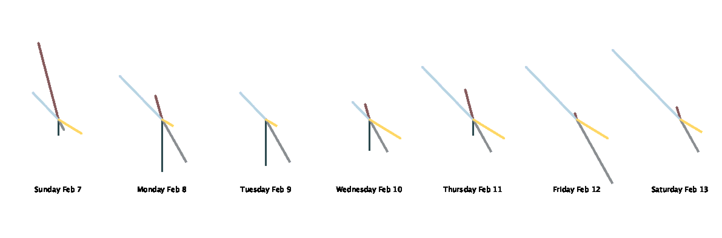
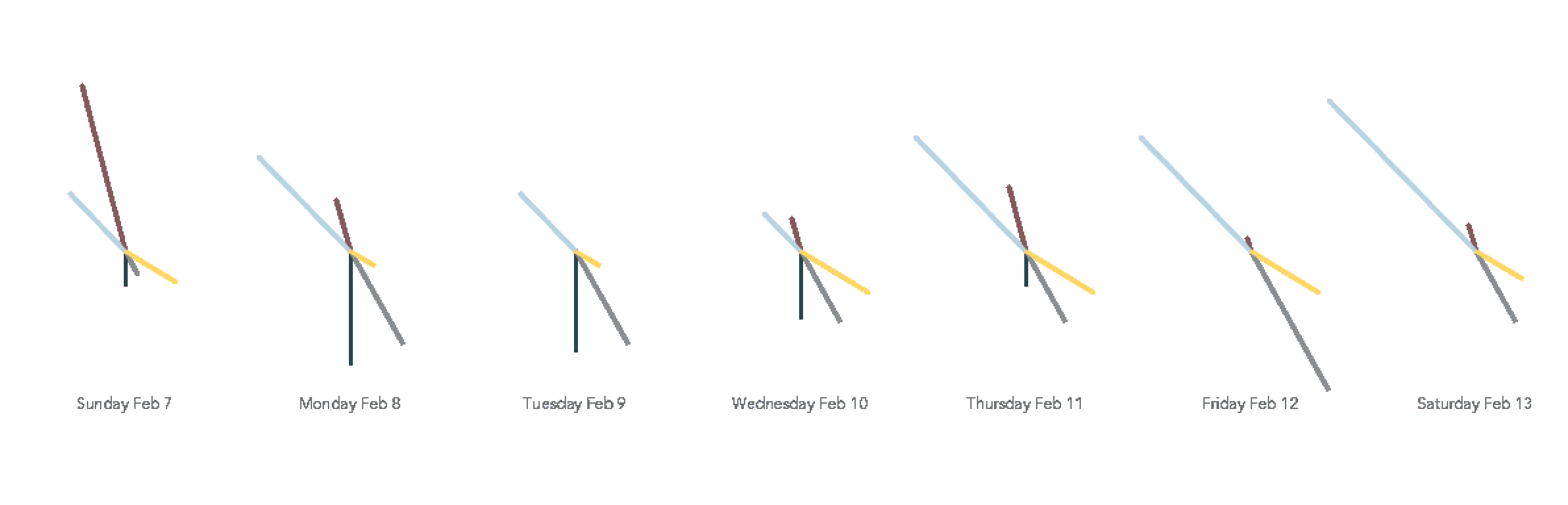
From there, I began experimenting with drawing the strokes in a circle.Second step in process of sketch; blurry text

It was rather unclear how long the lines actually were which was important since the length was supposed to convey the number of hours I spent engaged in a particular activity. I also was not vibing with the font.

I ended up drawing smaller circles for each day to have gridlines to show the number. I also learned how to load a font into Processing and used one of my favorite typefaces: Avenir!

process 3 of sketch; changed font to Avenir and made less blurry

One thing I needed to pay particular attention to was the order of drawing all the elements. Originally, I had my circles in the inner for loop which meant they kept getting drawn on top of so they were thicker than intended, they got drawn on top of the chart lines, and the obvious harm to performance.

Here is my final sketch!

final sketch!

And the code!

//class, meetings, social, work, self-care
float[][] data ={{1.25, 6.5, 1.0, 3.0, 2.25}, {4.25, 2.0, 4.0, 5.0, 1.0}, {3.75, 0.0, 4.0, 3.0, 1.0}, {2.5, 1.25, 3.0, 2.0, 3.0}, 
{1.25, 2.5, 3.0, 6.0, 3.0}, {0.0, 0.5, 6.0, 6.0, 3.0}, {0.0, 1.0, 3.0, 8.0, 2.0}};

PFont av;

String[] days = {"Sunday Feb 7", "Monday Feb 8", "Tuesday Feb 9", 
"Wednesday Feb 10", "Thursday Feb 11", "Friday Feb 12", "Saturday Feb 13"};

color[] palette = {#28464B, #855A5C, #8A8E91, #B8D4E3, #FED766};

String[] legend = {"class", "meetings", "social", "work", "self-care"};

int scale = 20;

void setup(){
  av = loadFont("Avenir-Book-48.vlw");
  hint(ENABLE_STROKE_PURE);
  size(1300, 500);
  background(255);
   fill(#6D7174);
  textAlign(CENTER);
  textFont(av, 36);
  text("How I Spend My Week (and too much time in meetings)", width/2, 50);
  drawKey();
  drawLines();
  textAlign(CENTER);
  textFont(av, 10);
  fill(#6D7174);
  textAlign(LEFT);
  text("Notes: The length of line corresponds to the number of hours spent that day engaging in that activity. The color corresponds to the activity.", 15, height-15);
}

//draws lines at top showing the colors and activities
void drawKey(){
  int x = 800/data[0].length;
  for (int a = 0; a < data[0].length; a++){
    stroke(palette[a]);
    strokeWeight(3);
    line(width/6 * a + x, 100, width/6 *a +x + 50, 100);
    textFont(av, 12);
    textAlign(LEFT);
    text(legend[a], width/6 *a +x + 65, 102);
  }
}

void drawLines() {
  textAlign(CENTER);
  int x = width / days.length;
  float angle = 360/data[0].length;
  for (int i = 0; i < data.length; i++) {
    //draws guiding circle gridlines
    textFont(av, 12);
 noFill();
      strokeWeight(0.5);
      stroke(#D4D8D8);
      circle(x * i + 100, height/2, 2*scale);
      fill(#D4D8D8);
      text("2", x * i + 100 + scale, height/2);
      noFill();
      circle(x * i + 100, height/2, 4*scale);
      fill(#D4D8D8);
      text("4", x * i + 100 + 2* scale, height/2);
      noFill();
      circle(x * i + 100, height/2, 6*scale);
      fill(#D4D8D8);
      text("6", x * i + 100 + 3* scale, height/2);
    fill(#6D7174);
    //draw day labels
    text(days[i], x * i + 100,height- 100);
    for (int j = 0; j < data[i].length; j++){
      //draws the chart lines
      translate(x * i + 100, height/2);
      rotate(angle * j);
      strokeWeight(3);
      stroke(palette[j]);
      line(0,0,0,data[i][j] * scale);
      fill(255);
      strokeWeight(1);
      ellipse(0, data[i][j] * scale, 7, 7);
      rotate(-angle * j);
      translate(-(x * i + 100), -height/2);
    }
  }
}