Final Project – Lime Liner

Concept and Implementation: 

For my final project, I created a digital version of the classic Etch-a-Sketch toy which utilizes both Arduino and P5JS. I personalized the design by using neon green and black colors to give it a modern, sleek look. The goal was to replicate the drawing experience of the original toy while adding new features that enhance the user’s creativity and leaving a personal mark on the concept. Additionally, to better reflect my altered version of the toy, I decided to name it Lime Liner.

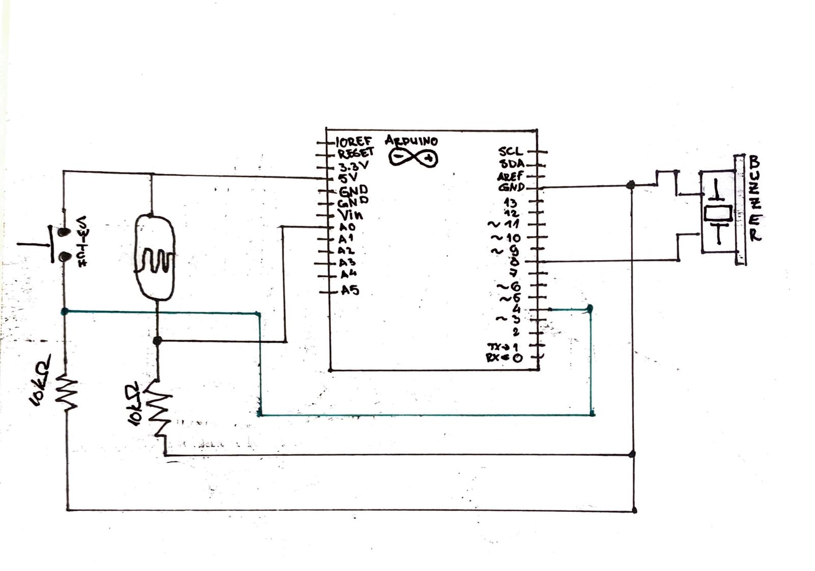
The Lime Liner was created using an Arduino Uno board and two potentiometers connected to analog pins A0 and A1. The potentiometers control the movement of the cursor on the screen. A switch connected to digital pin 2 was also used to clear the screen. The p5.js sketch is used to draw the cursor and lines on the canvas. The user interacts with the Etch-a-Sketch by turning the potentiometers to move the cursor horizontally and vertically, and pressing the switch to clear the screen. The cursor moves smoothly on the screen and leaves a trail as it moves. The user can create different patterns and shapes by changing the direction and speed of the cursor.

Arduino Code: 

The Arduino code initializes the serial communication and reads the values of the potentiometers and switch. It sends the values to the p5.js sketch using the Serial library.

// This code is for an Arduino project that receives data from p5.js and sends sensor data back to p5.js
// The inputs are:
// - A0: first potentiometer
// - A1: second potentiometer
// - 2: switch input

void setup() {
  // Serial communication is started to send the data
  Serial.begin(9600);

  // Set pin 2 as input
  pinMode(2, INPUT);

  // Bidirectional communication starts
  while (Serial.available() <= 0) {
    // Send a starting message to p5.js
    Serial.println("0,0");
  }
}

void loop() {
  // Waits to receive data from p5.js first and then starts executing
  while (Serial.available()) {

    // Parse the incoming data from p5.js
    int left = Serial.parseInt();
    int right = Serial.parseInt();
    
    // If a new line character is received, read the sensors and button and send the data back to p5.js
    if (Serial.read() == '\n') {
      int sensor = analogRead(A0);
      delay(5);
      int sensor2 = analogRead(A1);
      delay(5);
      int button = digitalRead(2);
      delay(5);

      // Send the sensor and button data to p5.js
      Serial.print(sensor);
      Serial.print(',');
      Serial.print(sensor2);
      Serial.print(',');
      Serial.println(button);
    }
  }
} 

P5js Code: 

The p5.js code sets up the canvas and draws the cursor and lines using the values received from the Arduino. It also includes functions to clear the screen and prevent the cursor from going outside the canvas.

// Variables for controlling color, position, and switch state
let xPos = 0; // horizontal position of the ellipse
let yPos = 0; // vertical position of the ellipse
let switchState = 0; // state of the switch that clears the Etch A Sketch

// Setup function, runs once when the sketch is loaded
function setup() {
  createCanvas(600, 400);
  textSize(18);
  background(255);
  frame();
}

// Counter variable for the while loop in draw function
let i = 0;

// Draw function, runs continuously to update the sketch
function draw() {
  // While loop to set the button state to 1 only once
  while (i < 1) {
    switchState = 1;
    i++;
  }

  // Map the xPos and yPos to the canvas size to control ellipse position
  fill("#39FF13");
  // Draw the ellipse at a position determined by the mapped xPos and yPos
  ellipse(
    map(xPos, 0, 1023, 70, width - 90),
    map(yPos, 0, 1023, 70, height - 80),
    3
  );

  // Check if the switchState is 1, and call the frame function to clear the sketch
  if (switchState == 1) {
    frame(); // calls the frame function i.e. restarts the sketch
  }
}

// Function to set up the serial connection when spacebar is pressed
function keyPressed() {
  if (key == " ") {
    setUpSerial();
  }
}

// Function to read data from the Arduino
function readSerial(data) {
  ////////////////////////////////////
  //READ FROM ARDUINO HERE
  ////////////////////////////////////

  // Check if there is any data received
  if (data != null) {
    // Split the message
    let fromArduino = split(trim(data), ",");
    // If the message is of the correct length, store the Arduino values
    if (fromArduino.length == 3) {
      xPos = fromArduino[0]; // Update the xPos value based on input from Arduino
      yPos = fromArduino[1]; // Update the yPos value based on input from Arduino
      switchState = fromArduino[2];
    }
    //////////////////////////////////
    //SEND TO ARDUINO HERE (handshake)
    //////////////////////////////////
    let sendToArduino = xPos + "," + yPos + "\n";
    writeSerial(sendToArduino);
  }
}

// Function to draw the frame of the Etch A Sketch
function frame() {
  // Draw the outer frame
  strokeWeight(120);
  noFill();
  stroke("#2BC20E");
  rect(0, 0, width, height);

  // Draw the inner frame
  fill("#010B12");
  strokeWeight(30);
  stroke("#010B12");
  strokeJoin(ROUND);
  rect(70, 70, width-140, height-140);

  // Draw the title 
  noStroke();
  fill("#1E1F21");
  textAlign(CENTER);
  textSize(30);
  textFont("Brush Script MT");
  text(" ~ Lime Liner ~ ", width/2, 40);

  // Draw the two knobs at the bottom
  noStroke();
  fill("#010B12");
  ellipse(width-570, 365, 50, 50);
  ellipse(570, 365, 50, 50);
}

Serial communication is used to send and receive data between the Arduino and p5.js. The Arduino sends the position of the potentiometers and button to p5.js, which uses this data to draw on the screen. The clear button also uses serial communication to send a signal from p5.js to the Arduino.

Areas I am proud of and future improvments:

I am particularly proud of the clean and modern design of the Etch-a-Sketch, which makes it stand out from other versions. I also spent a lot of time debugging both the physical and code components of the project to ensure that everything was functioning properly.

Since this was a back-up project, I am a bit disappointed that I did not have the skills and time to finish my initial idea of a radar. Regardless, I feel satisfied with the final version of my project. In the future, one area for improvement would be to add more features to the Lime Liner, such as the ability to change the color of the lines or adjust the thickness of the stylus. Another potential improvement would be to make the stylus wireless to allow for more freedom of movement. Additionally, the code could be optimized to reduce latency and improve performance and a game could be implemented in which the user will interact more with the project.


Final Project – User Testing

In order to gather feedback on the usability of my project, I conducted a user interaction test by having people try the project without any prompts or instructions. The purpose of this test was to evaluate how intuitive the design was and how well users were able to understand the mapping between the controls and the resulting experience.

Overall, the results of the test were mixed. Some users were able to figure out the controls quickly and enjoyed the experience, while others struggled to understand how the controls worked and what their effect on the project was. A common area of confusion was the use of the two potentiometers, as some users were unsure of which one controlled the horizontal and vertical movement of the line.

Despite the challenges some users faced, there were several areas of the project that worked well. Many users enjoyed the retro feel of the etch-a-sketch and appreciated the unique green and black design. The feedback on the physical controls was also positive, as users found them easy to use and responsive.

Based on the results of the user interaction test, there are several areas that could be improved in the project. One approach could be to provide more detailed instructions or visual aids to help users understand the controls and how they affect the project. Another potential improvement could be to add a feature that allows users to save and share their creations, adding a new level of engagement and creativity to the project. Also, the knobs of the potentiometers should be made bigger so the users can control them more easily.

Final Project Proposal – Radar

Concept

As someone who is interested in physical computing, I have been inspired by previous DIY radar projects that use ultrasonic sensors and servo motors to detect objects in real-time. However, to make my project more original and challenging, I will use P5.js, a JavaScript library for creative coding, instead of Processing, which is commonly used in similar projects. By incorporating P5.js, I hope to create a unique and interactive radar system that combines hardware and software components. The concept of the project is to build a radar system that can detect objects and display their location and distance in real-time. The system will consist of an ultrasonic sensor, a servo motor, an Arduino board, and a computer running a P5.js program.

Technical aspect

For the Arduino program, I plan to use the ultrasonic sensor to detect the distance of objects in front of it. I will then use a servo motor to rotate the sensor and sweep it across a 180-degree arc. At each angle, the program will read the distance measurement and send this data to the P5.js program over the serial port. Additionally, I plan to control an LED to indicate the presence of an object within a certain distance threshold.

The P5.js program will receive the data from the Arduino program and use it to display the location of the detected object on a radar screen. Using polar coordinates, the program will map the distance and angle of each object and display them as a dot on the radar screen. The program will also include a graphical user interface (GUI) that allows me to adjust the distance threshold and other parameters.

To communicate between the Arduino and P5.js programs, I will send data over the serial port. The Arduino program will send the angle and distance of each detected object, as well as the state of the LED. The P5.js program will use this data to update the radar screen and the GUI.

Week 11 – Exercises

Exercise 1: Control p5js through Arduino 

For this exercise we had to establish serial communication between p5js and Arduino. Then we had to use an analog sensor to control some values in p5js. I used a photoresistor to control the movement of a circle in p5js.

p5js Code: 

// This program reads data from an Arduino board via serial connection and uses the data to control the position of an ellipse drawn on a P5JS canvas.

// Declare a variable to hold the x-coordinate of the ellipse.
let xValue = 0;  
// Set up the canvas.
function setup() {
  createCanvas(400, 400);
}
// Draw the ellipse on the canvas and display a message indicating whether or not the serial connection is active.
function draw() {
  background(0);
    // If the serial connection is not active, display a message telling the user to press the space bar to select a serial port.
  if (!serialActive) {
    fill(255);
    text("Press Space Bar to select Serial Port", width/4, 30);
  } 
   // If the serial connection is active, display a message indicating that it is connected and draw an ellipse at the current x-coordinate.
  else {
    fill(255);
    noStroke();
    text("Connected", 170, 30);
    stroke(255);
    fill("#39FF14")
    ellipse(xValue, height/2, 50, 50);
  }
}

// Set up the serial connection when the space bar is pressed.
function keyPressed() {
  if (key == " ") {
    setUpSerial();
  }
}

// Read the incoming data from the serial port and map it to the range of the canvas. 
function readSerial(data) {
  if (data != null) {
// Map the incoming data from the range of 0 to 1023 to the range of 0 to the width of the canvas.
    xValue = map(data, 840, 0, width, 0);
  }
}

Arduino Code: 

// This program reads data from a light sensor connected to analog pin A0 of an Arduino board and sends the data to a serial port (p5js).

// Define the analog pin to which the light sensor is connected.
const int lightSensor = A0;

// Set up the serial connection.
void setup() {
  Serial.begin(9600);
  
  // Set the light sensor pin as an input.
  pinMode(lightSensor, INPUT);
}

// Read the value from the light sensor and print it to the serial port.
void loop() {
  // Read the value from the light sensor.
  int lightValue = analogRead(lightSensor);
  
  // Print the light value to the serial port.
  Serial.println(lightValue);
}

Video:

Exercise 2: Control Arduino through p5js

For the second exercise we had to control Arduino through p5js. I designed a circuit with an LED whose brightness was controlled by clicking the mouse in different positions.

P5js Code: 

//Declare and intialize the duty variable to 0
let duty = 0;
//Create canvas and set text size to 18
  function setup() {
    createCanvas(640, 480);
    textSize(18);
  }

  function draw() {
  background(0);
    // Check if the serial port is not active
    if (!serialActive) {
      // Display a message to prompt the user to press the space bar to select a serial port
      fill(255);
      text("Press Space Bar to select Serial Port", 20, 30);
    } else {
      fill(255);
      // Display a message indicating that the serial port is connected
      text("Connected", 20, 30);
      // Log the duty value to the console
      console.log(duty);
      // Create a string to send to the Arduino over serial with the duty value and a newline character
      let sendToArduino = duty + "\n";
      // Send the string to the Arduino over serial
      writeSerial(sendToArduino);
    }  
   }
  function keyPressed() {
    // Check if the space bar is pressed
    if (key == " ") {
      setUpSerial();
    }
  }
  function mousePressed() {
    // Map the mouseY value to a duty value between 0 and 1023
    duty = int(map(mouseY, 0, height, 0, 1023));
  }
  function readSerial(data) {
  }

Arduino Code:

Unfortunately I lost the Arduino code as I over wrote it with the code from the 3rd exercise without previously saving.

Video: 

Exercise 3: Two-way communication between p5js and Arduino

For this exercise we had to establish a two-way communication. I used a photo receptor to control the direction of movement of a circle in p5js, and used p5js to turn on an LED every time that circle hit the ground.

P5js Code: 

// Ball simulation variables
let ballVelocity;
let ballGravity;
let ballPosition;
let ballAcceleration;
let ballWind;
let ballDrag = 0.99;
let ballMass = 50;

// Arduino communication variables
let arduinoWindSensorValue = 0;
let arduinoLedOn = 0;

function setup() {
createCanvas(400, 400);
ballPosition = createVector(width/2, 0);
ballVelocity = createVector(0,0);
ballAcceleration = createVector(0,0);
ballGravity = createVector(0, 0.5*ballMass);
ballWind = createVector(0,0);
}

function draw() {
background(0);
fill(255);
if (!serialActive) {text("Press Space Bar to select Serial Port", width/4, 30); }
else {text("Connected!", 165, 30); }

fill("#39FF14");
applyForce(ballWind);
applyForce(ballGravity);
ballVelocity.add(ballAcceleration);
ballVelocity.mult(ballDrag);
ballPosition.add(ballVelocity);
ballAcceleration.mult(0);
ellipse(ballPosition.x,ballPosition.y,ballMass,ballMass);

if (ballPosition.y > height-ballMass/2) {
ballVelocity.y *= -0.9; // A little dampening when hitting the bottom
ballPosition.y = height-ballMass/2;
arduinoLedOn = 1; //If the ball makes contact with the ground, the LED will be ON
}
else {arduinoLedOn = 0;} //Else the LED will be OFF

//If the arduinoWindSensorValue value from the Arduino that was mapped is greater than 0, then it will move the ball to the right
if(arduinoWindSensorValue > 0) {
ballWind.x = 0.5;
}

//Else if the arduinoWindSensorValue value from the Arduino is less than 0, it will move the ball to the left
else if(arduinoWindSensorValue < 0) {
ballWind.x = -0.5;
}

//If it's 0, aka no wind, then it will just keep the ball where it is, no wind.
else {
ballWind.x = 0;
}
}

function applyForce(force){
// Newton's 2nd law: F = M * A
// or A = F / M
let f = p5.Vector.div(force, ballMass);
ballAcceleration.add(f);
}

function keyPressed(){
if (key == "m"){
ballMass=random(15,80);
ballPosition.y=-ballMass;
ballVelocity.mult(0);
}

if(key == " ") {
setUpSerial();
}
}

function readSerial(data) {
if(data != null) {
//Sends the arduinoLedOn information to the Arduino
let sendToArduino = arduinoLedOn + "\n";
writeSerial(sendToArduino);
//Reads the arduinoWindSensorValue values from the Arduino and maps its value to either -1 or 1 to correspond to wind direction.
arduinoWindSensorValue = map(data, 0, 1023, -1 , 1);
}
}

Arduino Code: 

// Define pin constants
const int LED_PIN = 8;
const int LIGHT_SENSOR_PIN = A0;

void setup() {
  // Start serial communication
  Serial.begin(9600);

  // Set pin modes
  pinMode(LED_PIN, OUTPUT);
  pinMode(LIGHT_SENSOR_PIN, INPUT);

  // Check LED wiring
  digitalWrite(LED_PIN, HIGH);
  delay(200);
  digitalWrite(LED_PIN, LOW);

  // Wait for serial connection
  while (Serial.available() <= 0) {
    Serial.println("0");
  }
}

void loop() {
  while (Serial.available()) {
    // Read LED ON/OFF information from p5js and switch LED on/off accordingly
    int led_on = Serial.parseInt();
    digitalWrite(LED_PIN, led_on);

    // Read light value from the sensor and send it to p5js
    int light_value = analogRead(LIGHT_SENSOR_PIN);
    Serial.println(light_value);
  }
}

Video: 

Final Project – Arduino Radar: 

The project I am working on involves building a radar system using Arduino and P5JS. The radar will use an ultrasonic sensor to detect objects in the environment and display them on a graphical interface built with P5JS. The graphical interface will show the real-time location of the detected objects on a radar screen, with different colors indicating different distances. This project aims to showcase the capabilities of Arduino in building complex and interactive systems and to demonstrate the potential of radar technology in various applications, such as robotics, security, and environment monitoring. By combining hardware and software, this project will offer a unique and innovative solution for users who are interested in exploring the world of DIY electronics and sensor technology.

Week 10 – Light Theremin (Stefan and Arslan)

Concept:

For this assignment, we wanted to create a version “Theremin” that will be linked with the light sensor and will produce sound based on the light intensity received by the sensor on Arduino board. Additionally, we’ll add the switch to this Light Theremin to change the frequency of the sound and to play different sounds using the light sensor. The frequency only changes while the button is pressed, we did this to change tune while playing the theremin which makes it easier for the user to play different tone from both frequencies. In short, the analog in takes values from the light sensor and these values are converted within a certain limit to be played through the buzzer. When the button is pressed, the limit of these values changes and thus giving us the tone of higher frequency.

SCHEMATIC:
Video:

Code:

// create variable to hold sensor value
int sensorValue;
// UNO's analog read sensors use "analog to digital converter" (ADC),
// which means it divides the reading coming from the sensor (0 to 5 volts) into 1024 equal steps.
// Thus, the reading from our photoresistor could range from 0 to 1023,
// however it is unlikely to use the full range so we will calibrate it.
// For now, create variables to hold the high and low value for our photoresistor range,
// make them the opposite of the max/min values and we will calibrate them down.
int sensorLow = 1023;
int sensorHigh = 0;
// set the LED pin, 13 is the built in LED
const int ledPin = 13;
int switchFreq = 4;
int switchVal;


void setup() {
 
 
  pinMode(ledPin, OUTPUT);
  pinMode(switchFreq, INPUT);
 
  digitalWrite(ledPin, HIGH);
 
  delay(500);
 
  digitalWrite(ledPin, LOW);
  delay(500);
  digitalWrite(ledPin, HIGH);
  delay(500);  
  digitalWrite(ledPin, LOW);
  delay(500);
  digitalWrite(ledPin, HIGH);

  // after it blinks for 2 seconds, its time to calibrate the photoresistor readings
  // create a loop with while() that lasts for 5000 ms to calibrate the light sensor according the setting,
  while (millis() < 5000) {
    // use analogRead() to get a reading from the photoresistor,
    sensorValue = analogRead(A0);
    // create two conditions using if() to calibrate the max and min sensor values,
    // raise the sensorHigh if the current reading is higher:
    if (sensorValue > sensorHigh) {
      sensorHigh = sensorValue;
    }
    // lower the sensorLow if the current reading is lower:
    if (sensorValue < sensorLow) {
      sensorLow = sensorValue;
    }
  }
 
  // turn the LED off, calibration is done!
  digitalWrite(ledPin, LOW);
}


void loop() {
  //read the input from A0 and store it in a variable
  sensorValue = analogRead(A0);
  switchVal = digitalRead(switchFreq);

  // map(currentValue, oldRange1, oldRange2, newRange1, newRange2)
  // I reverse their order (high, low) so that shading the photoresister will cause a higher tone.
  // the new range is the range of Hz to use to produce sound, which for UNO can be from 31 to 65535 Hz.
  // I set it from 0 to 300, which is a more normal sound range and if a button is pressed I change the values between 500 to 1000
  // since we start at 0, full light will make no tone, full shade will make the highest tone.
  if (switchVal == HIGH){
  int pitch = map(sensorValue, sensorHigh, sensorLow, 500, 1000);
  tone(8, pitch, 10);
  }
  else{
    int pitch = map(sensorValue, sensorHigh, sensorLow, 0, 300);
    tone(8, pitch, 10);
  }
  // use the tone function to create sound in the piezo,
  // tone(pin#, value, milliseconds)
 

  // add a delay to make the current tone sustained for a few ms to adjust the quality of the tone
  delay(15);
}

Future improvements:

For future, we want to use more than 2 limits of frequencies and we want to add instruments that could be switched using the button. After completing this project, we realised that playing sound using the light sensor is easier than any other sensor since it only requires basic movements of hands to block the light or allow the light to the sensor. Thus, in future, we’d like to add more instruments like electric guitar frequencies and allow users to switch between these instruments using the switch buttons.


Week 9 – Switches and LEDs

Concepts and methods

For this assignment, I wanted to simulate police lights so I used two LEDs (blue and red) and two push (button switches). Each switch turns on the respectively colored LED, and when both switches are pressed the LEDs blink continuously looking like police lights.

Schematic

Code

//Declare the button switches and the LEDs 
const int BUTTON1 = 2;
const int BUTTON2 = 5;
const int LED1 = 8;
const int LED2 = 12;
int BUTTONstate1 = 0;
int BUTTONstate2 = 0;

void setup()
{
//Declare the buttons as input and the LEDs as output
pinMode(BUTTON1, INPUT);
pinMode(BUTTON2, INPUT);
pinMode(LED1, OUTPUT);
pinMode(LED2, OUTPUT);
}

void loop()
{
// Turn on the blue LED by pressing the blue switch
BUTTONstate1 = digitalRead(BUTTON1);
if (BUTTONstate1 == HIGH)
{
digitalWrite(LED1, HIGH);
}
else{
digitalWrite(LED1, LOW);
}
//Turn on the Red LED by pressing the red switch
BUTTONstate2 = digitalRead(BUTTON2);
if (BUTTONstate2 == HIGH)
{
digitalWrite(LED2, HIGH);
}
else
{
digitalWrite(LED2, LOW);
}
//Blink the two LEDs when the two switches are pressed
if (BUTTONstate1 == HIGH && BUTTONstate2 == HIGH){
digitalWrite (LED1, HIGH);   
digitalWrite (LED2, LOW);   
delay(750);  // Wait 750ms  
digitalWrite (LED1, LOW);  
digitalWrite (LED2, HIGH);  
delay(500);  // Wait 500ms 
}
}

Video

Future Improvements 

In the future, I would like to experiment with a greater number of LEDs. Additionally, I would like to implement analog switches such as the potentiometer next.

Assignment – Do Not Disturb (Unusual Switch)

Concept and Methods: 

In the past, I’ve spent a significant amount of time trying to use my card to open a locked room door. All that inspired me to create this circuit which indicates whether a door is locked from the inside using a simple LED circuit. I built it using the SparkFun inventor’s kit and some spare foil I had laying around. I realized my idea by putting two wires inside the lock hole in the door frame and having the lock itself act as a switch as it’s made from metal and it is conductive. I additionally wrapped the metal endings of the wires with tin foil to increase the surface area and ensure that the lock touches on both of them connecting the circuit.

Reflection 

This assignment was somewhat tricky to record as I was not able to record the exact switching on because it was going on inside the door frame. Additionally, I can improve this as it is visible in the video that the led flickers as the door unlocks which implies something loose in the setup. Beside these points, I think I executed this well as it works and that can be heard in the video. Finally, I had a bunch of fun putting this project together and I look forward to learning more about physical computing.

Midterm Project – Duck Hunt

Duck Hunt sketch: 

For this assignment, I researched retro arcade games and decided I want to make a replica of the classic NES game Duck Hunt. Initially, I started with the background on which I built the rest of the game. Then, I used a sprite sheet that changes the ducks to dead ducks when shot. That was done using the following code, which is also the code that decides the gravity of the falling duck:

if (shot == true) {
  speed = -7;
  speed2 = 0
  push();
  noStroke();
  fill(220);
  duck(deadDuck);
  pop();
  
  if (y > 440) {
    shot = false;
    x = random(5, 580);
    speed = random(4,12);
    speed2 = random(-7,7);
    score += 1;
  }
}

I had several versions of the game until I decided to go with the final one in which you have unlimited ammo but a limited time to shoot as many ducks as possible. This way, the game can be played by anyone, however the score gives it a competitive edge in a sense that players can compete with their own previous score.

Regarding the code and the technical aspect of my assignment, I would say I am most proud of setting the timer to countdown from whatever value we assign to it. This was done with the following code:

fill(0, 0, 0);
  textSize(30);
  text("Time Left:" + timer, 25, 380)
  if (frameCount % 60 == 0 && timer > 0) {
    timer --;
  }
  if (timer == 0) {
    //text("GAME OVER", 200, 200);
    window.location.reload();

The timer additionally ends the game and displays the home screen. This particular switch from the home screen to the game was a problem that I was luckily able to overcome. Additionally, I ran into a problem while using OOP in one of the earlier versions. As I could not fix this problem I decided just to switch up and not use OOP. This is one of the few key changes that should be done to improve the game in the future. Other than this, I should improve the spawning points of the ducks as well as implement another paradigm to run the game including limited ammo, power ups and difficulty levels.

Finally, this game has a lot of space to improve, but it is a good starting point. I personally chose this game in order to recreate the feelings and experience of hunting for ducks on the NES using the gun controllers. I plan on doing this with the help of Arduino.


Assignment 4 – Generative Text

Concept

Recently, I have been playing through the story mode of UBISOFT’s Assassin’s Creed: Valhalla. This experience, paired with the recent trip to UBISOFT, inspired me to create this piece. I decided to use the slogan of the brotherhood from the Assassin’s Creed lore, and additionally I used an online translator to convert the slogan from latin to elder futhark scripture. This was done to tribute the Viking culture and their language with respect to the game.

Code 

For this assignment, I experimented a bit with using external media such as images and sound. I would say that the biggest part of my creative process for this assignment was choosing the right image on which the text displayed would be comprehensible.

Additionally, what proved to be a challenge was determining all the relative dimensions which determined the amount of text being displayed.  In order to not hard code them, I spent quite some time defining them to get what I wanted. The main goal was to have the mouse X-coordinate control the amount of text being displayed. This was done through the following code:

textSize(32);
textAlign(CENTER, BOTTOM);
let middle1 = sourceText1.length / 2;
let left1 = middle1 - ((mouseX / width) * middle1);
let right1 = middle1 + ((mouseX / width) * middle1);
//Draw a number of characters from the string depending on the mouse X coordinate
text(
  sourceText1.substring(left1, right1+1),
  width/2, height/10.01);

Eventually I got the following sketch as the final version for this assignment:

Future Improvements

All in all, I am pretty satisfied with the way this assignment turned out for me. I was able to implement things we learnt in class and relate them to a lot of interests that I have. In the future, I would like to focus more on maybe composing an image similar to this one with OOP.


Assignment 3 – OOP

Concept 

Using object oriented programming, I was able to create a piece of art which resembles everyday pressure and stress. Each circle, gets a randomly assigned color from the blue end of the spectrum. This is to symbolize the blues everyone faces every once in a while. Additionally, I wanted to implement something which takes away this pressure and so I did.

Code 

This assignment was tricky to some extent as it was the first time I was facing OOP. However, by revising the class material and looking over online resources along with the p5js Reference, I was able to tackle it. I created a class for the circles and included four arguments in the constructor: x and y coordinates, radius and color.  Then using a for loop, I created a program which assigns a random value to these arguments. This was done by this following code:

// Create 100 circles with random positions, sizes, and colors
for (let i = 0; i < 100; i++) {
  let x = random(width);
  let y = random(height);
  let r = random(10, 15);
  let c = color(random(30), random(70), random(255));
  let circle = new Circle(x, y, r, c);
  circles.push(circle);
}

Additionally, as I wanted to add the option of clearing the canvas and resetting the animation, I wrote an if statement using some of the p5js built in functions. This allowed for the animation to be restarted just by pressing space bar. Following is the if statement I used:

function keyPressed() {
  if (key === "space") {
    circle.reset();
  } 
}

Finally, I was left with the final version of my artwork which can be seen below:

Reflection

For this assignment, I felt like I was not able to fully express my creative thought as I was not familiar with the technical aspect of OOP. However, I am glad I was able to finish it and I am eager to learn more about the implications of OOP in generative art.