link to concept in more detail: link
link to Arduino and physical structure updates in more detail: link
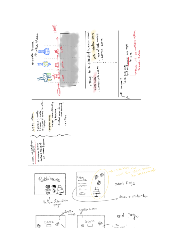
concept:
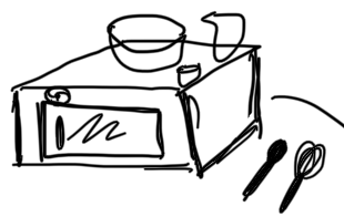
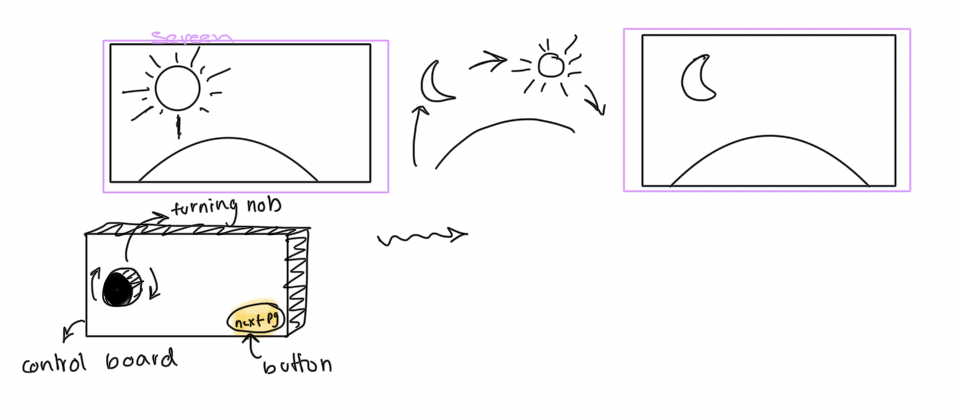
My project is an interactive kid’s recipe book. I tried to mimic an interactive kid’s book where children get to interact with the story they are reading.
How does the implementation work?
interaction design
I wanted the user to interact with the project in a similar way that they would interact with an interactive book in those ways:
-
-
-
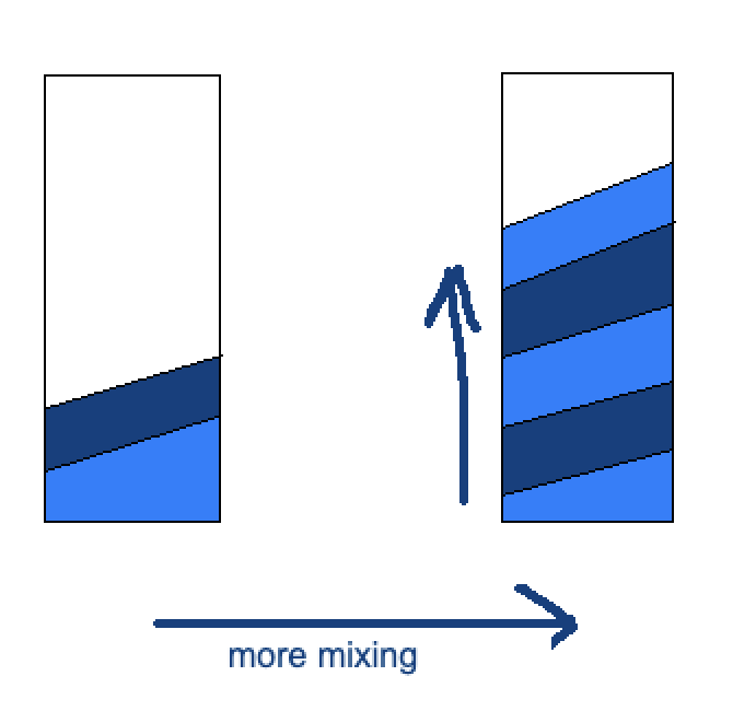
- the user should be able to to interact with the current page as many times as they wish. ex a child can keep mixing the batter as long as they want. I might improve the game in the future to include a bar on the side of the screen that monitors the mixing/pouring progress and would indicate when the batter has been mixed enough for example. this could make the game more interesting for older people since this would introduce a challenge)
- the user should be able to to interact with the current page as many times as they wish. ex a child can keep mixing the batter as long as they want. I might improve the game in the future to include a bar on the side of the screen that monitors the mixing/pouring progress and would indicate when the batter has been mixed enough for example. this could make the game more interesting for older people since this would introduce a challenge)
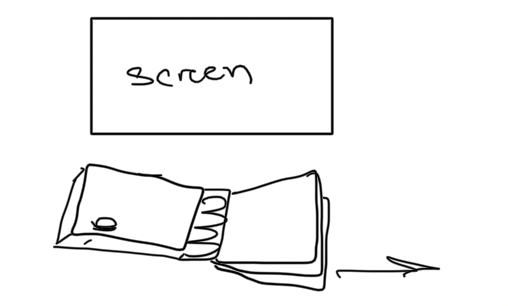
- user should be able to move through the page on their own pace (so I added a “next” button, but perhaps in the future I can add a back button)
-
-
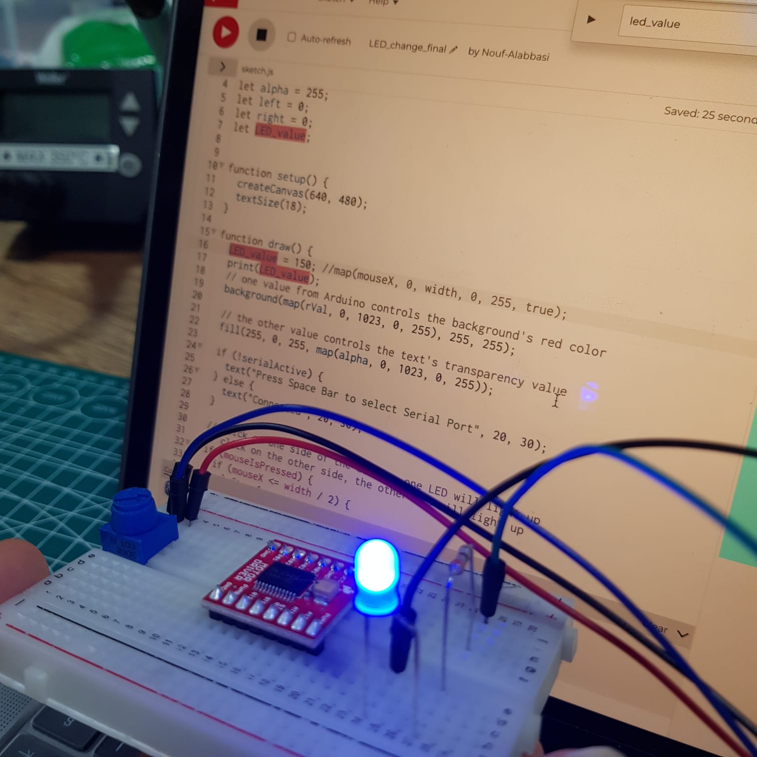
Arduino code
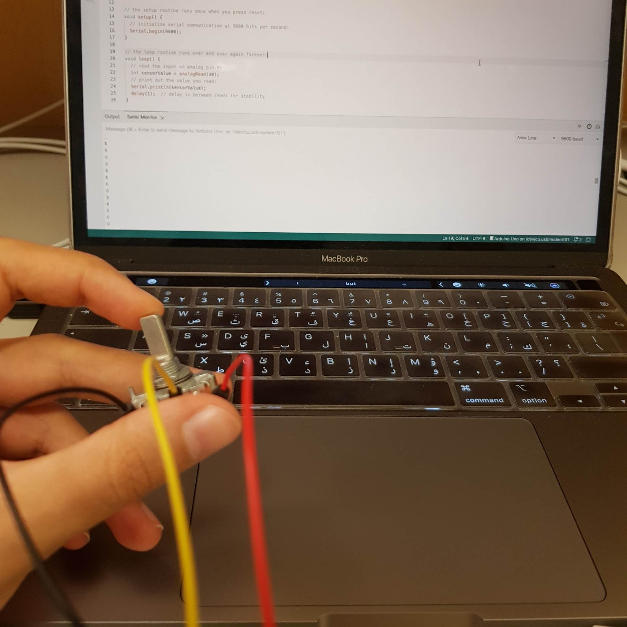
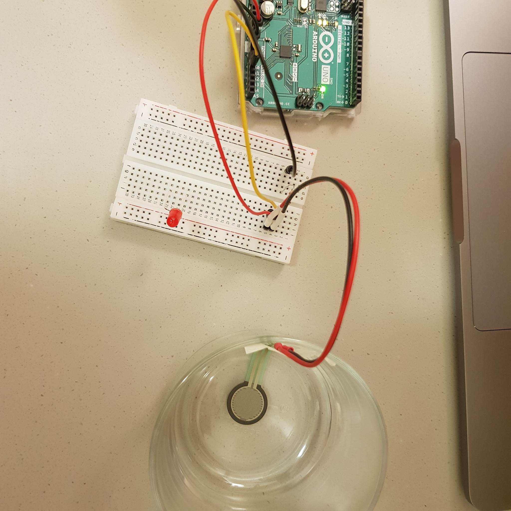
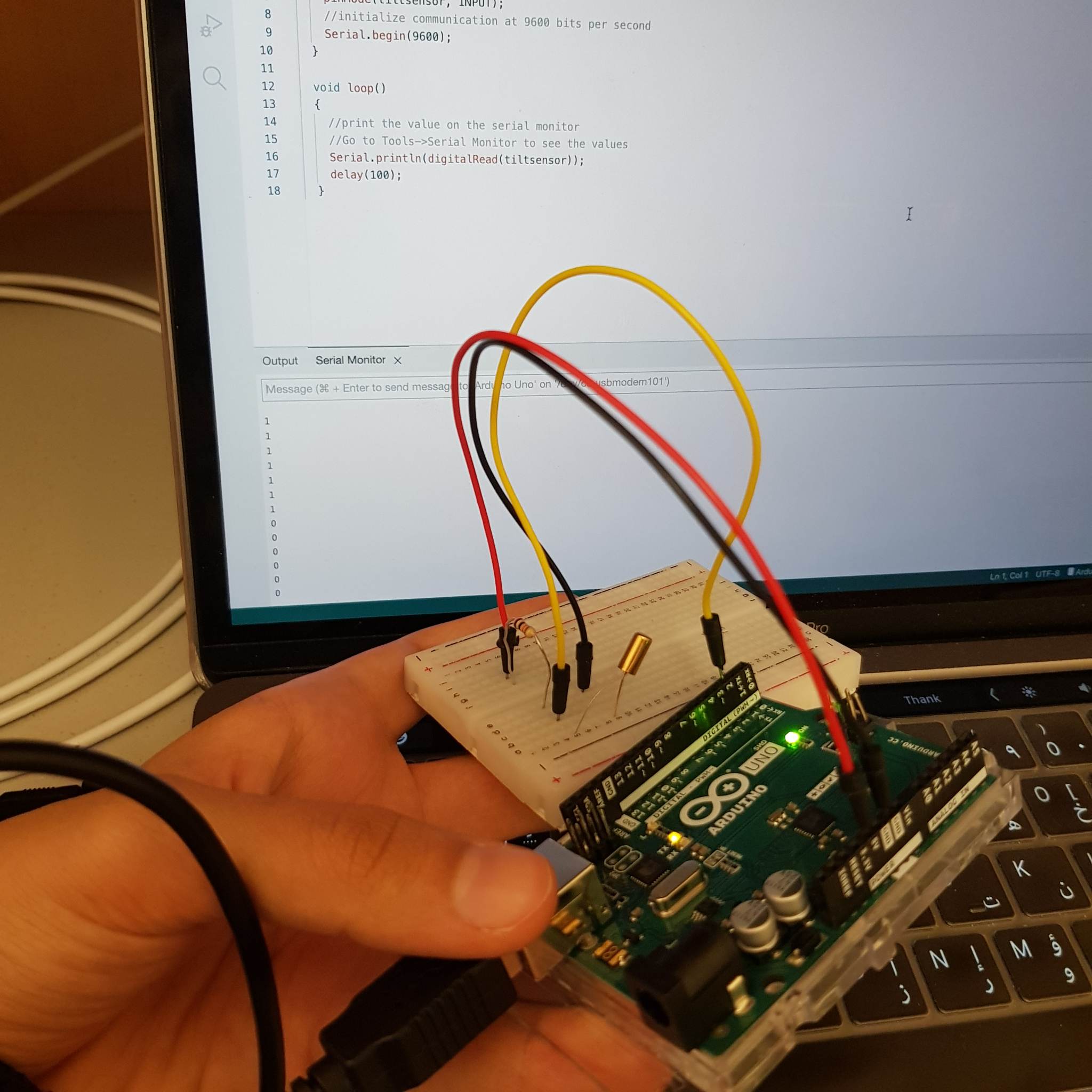
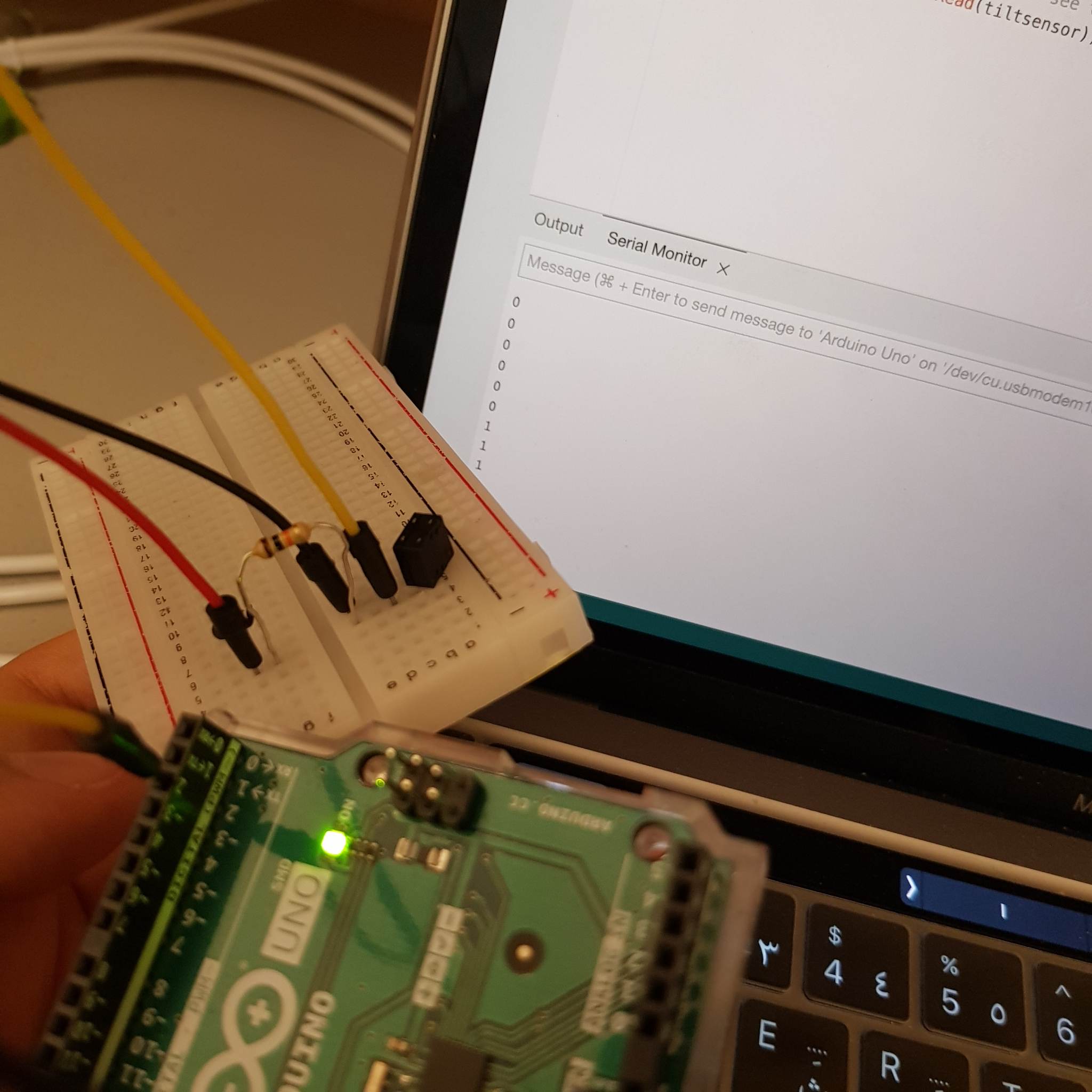
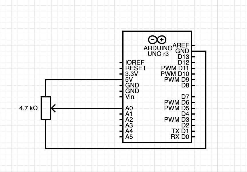
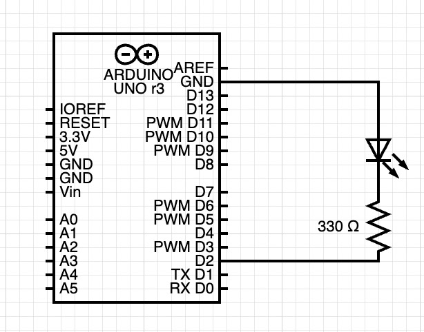
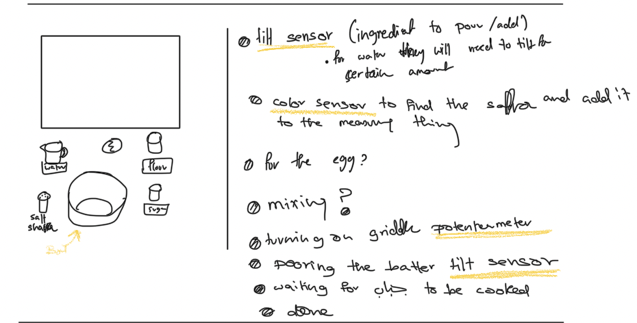
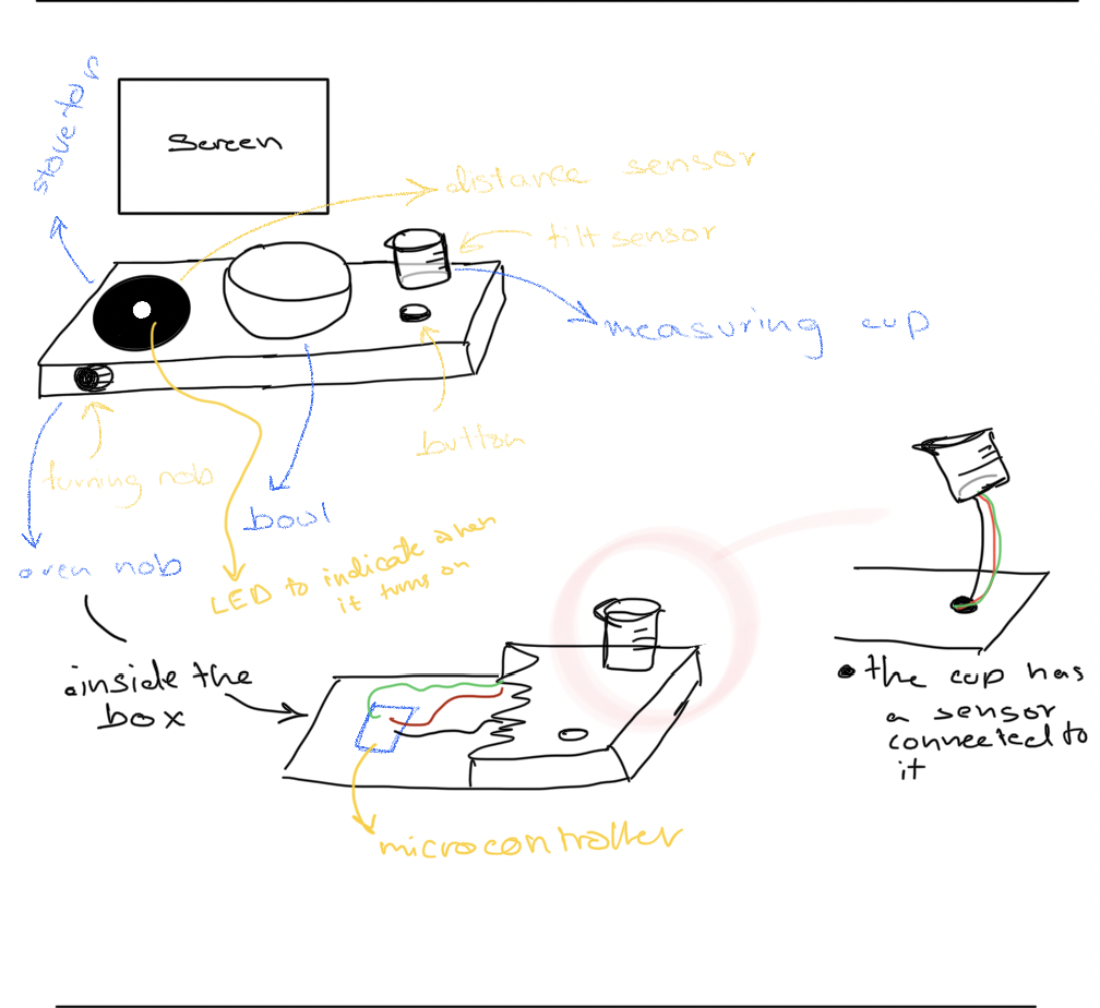
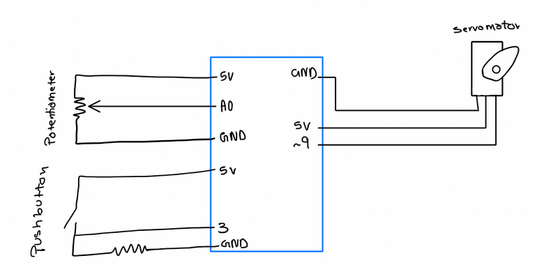
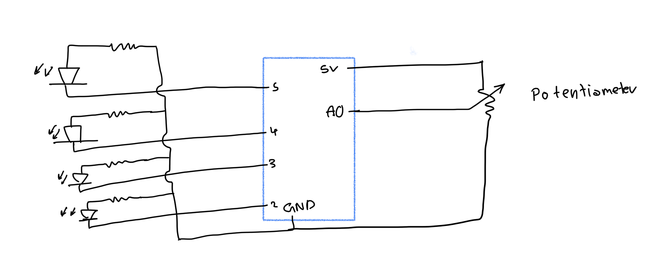
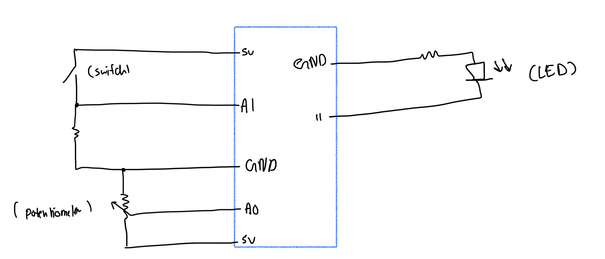
The Arduino code sends the data from all the sensors to P5js, and would receive the state of the oven LED from p5js. Here are some of the sensors and their uses:
-
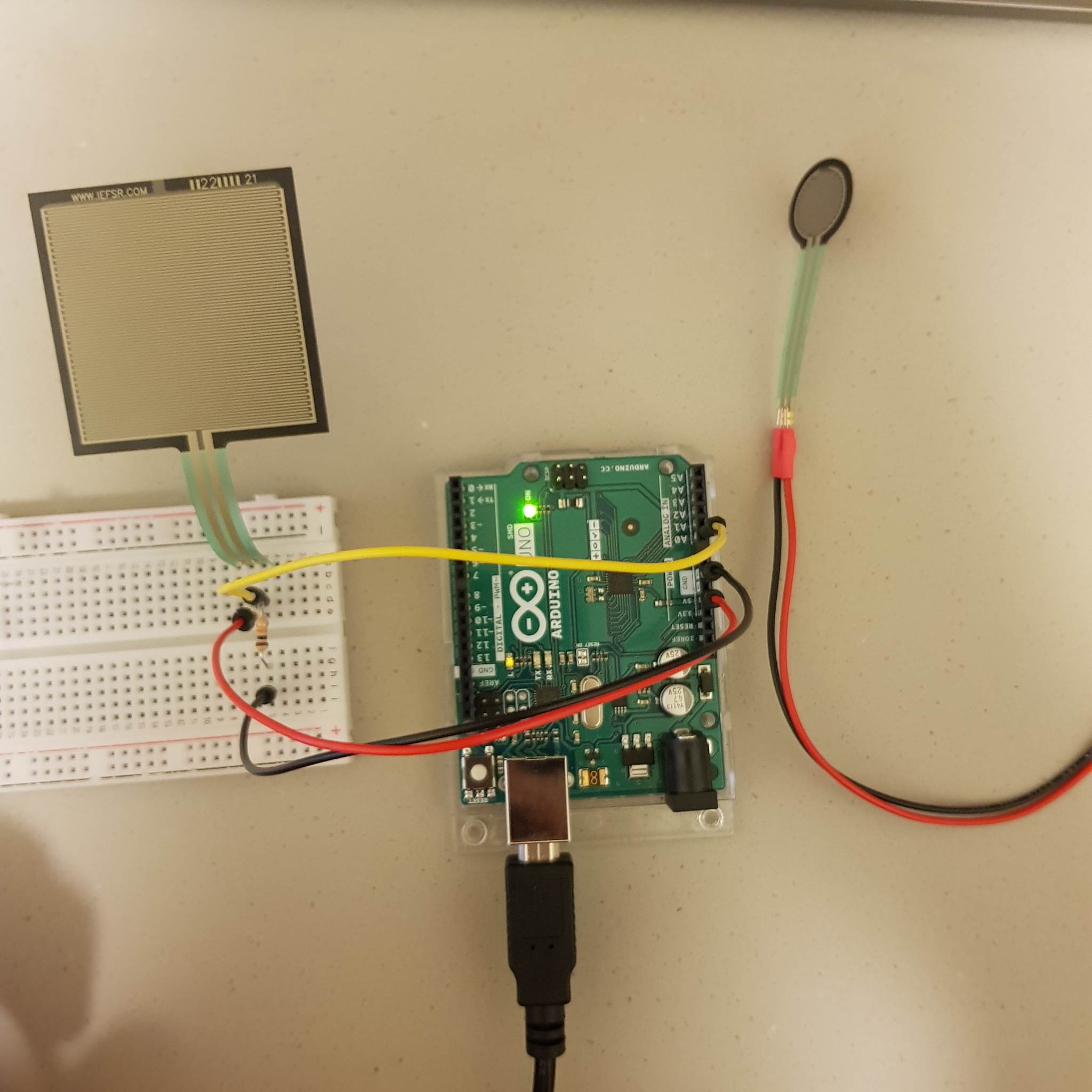
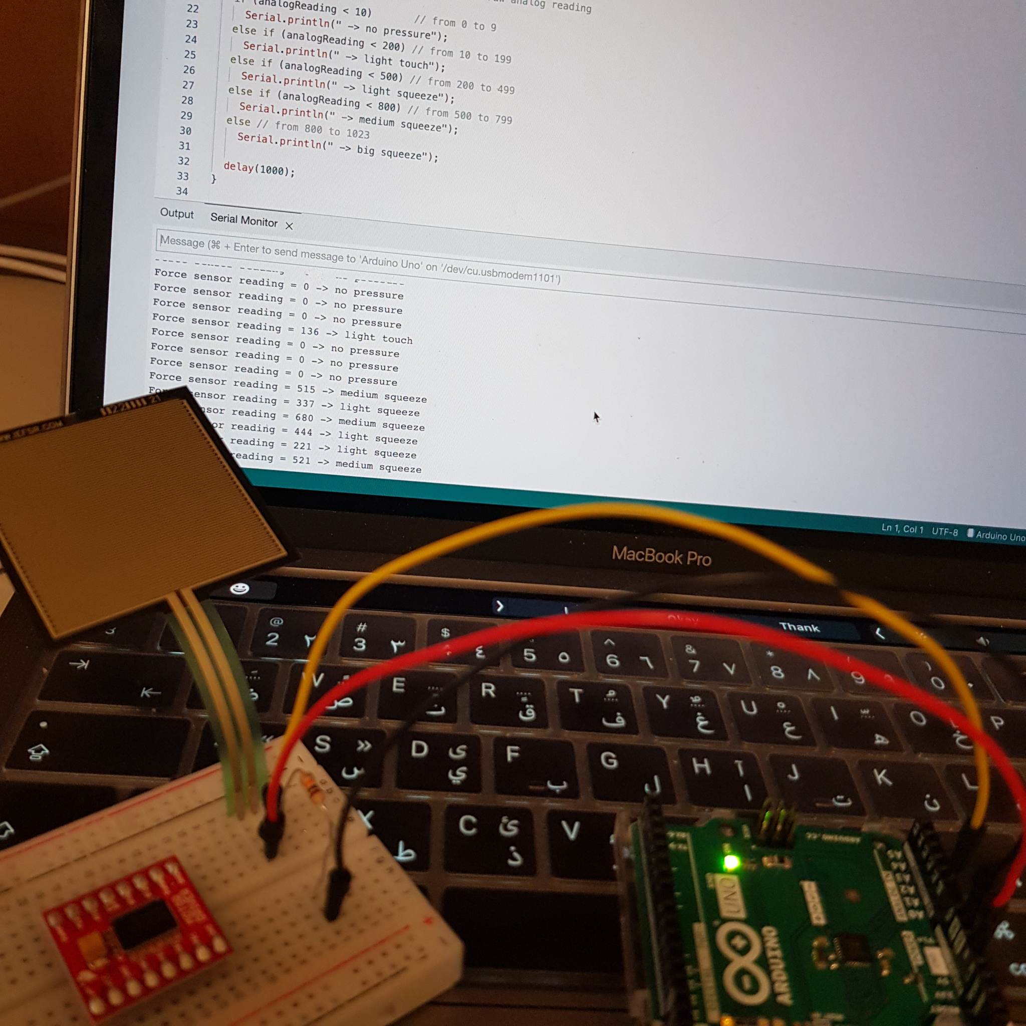
- force sensor – detect mixing motion
- tilt sensor – detect pouring
- ultrasonic sensor – detect person picking up ingredients
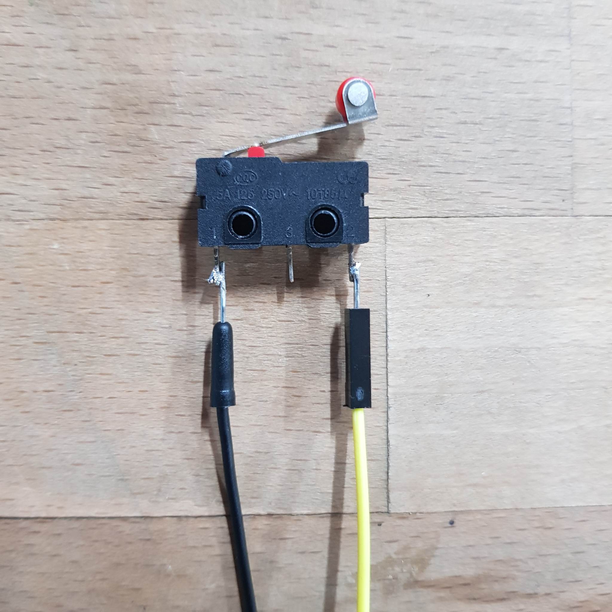
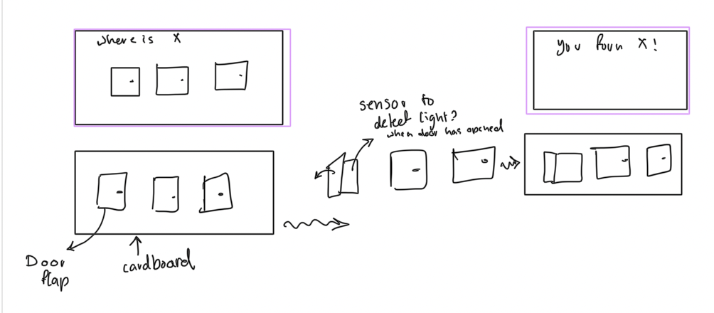
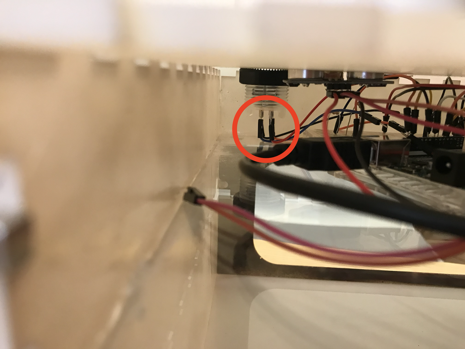
- limit switch – to detect the oven door opening and closing
one things that I hope to implement in the future is to implement code that prevents the button from continuously returning 1 if it continuously pressed(I’m currently using a work around in p5js)(Joonha has a snippet of code that handles that that I could possibly use).
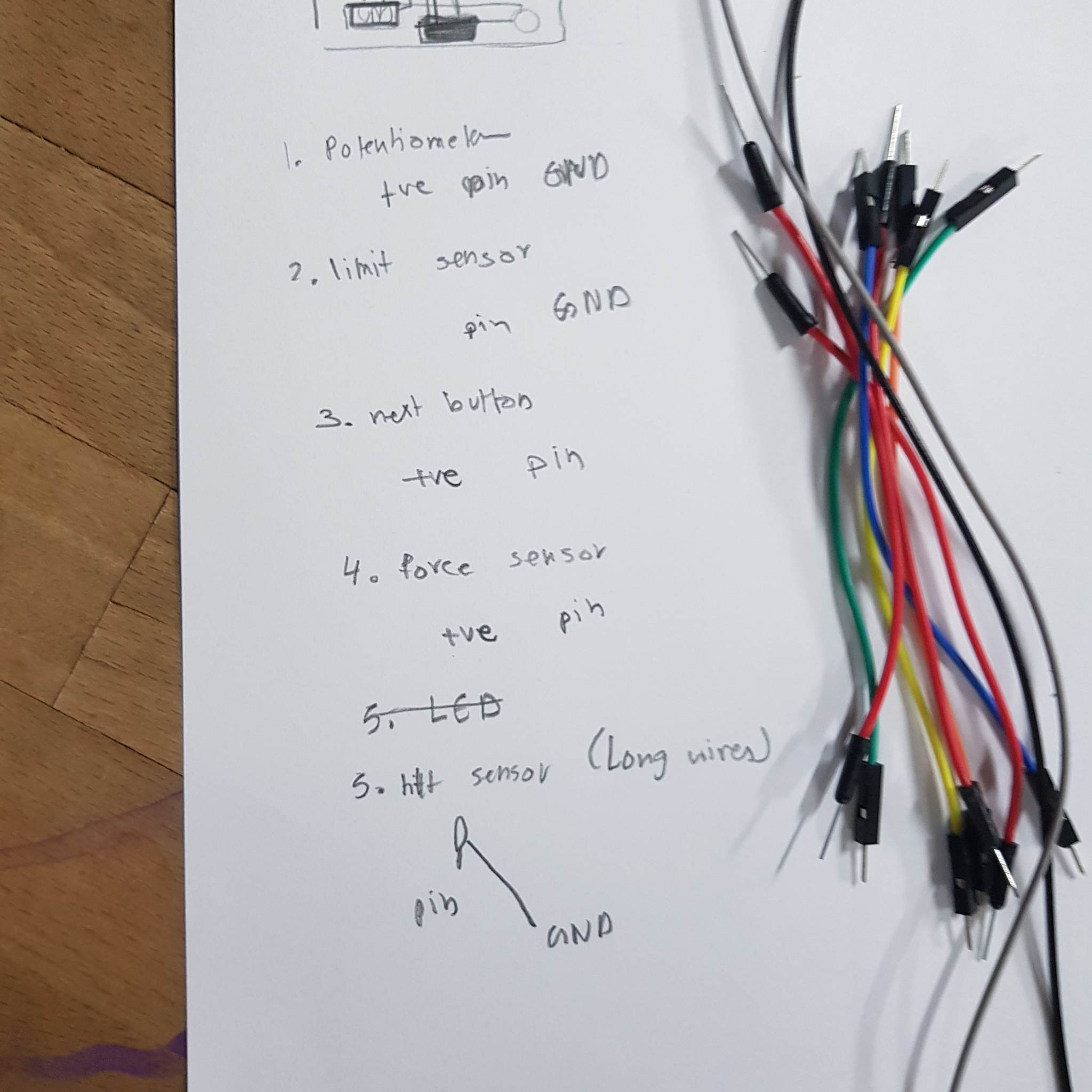
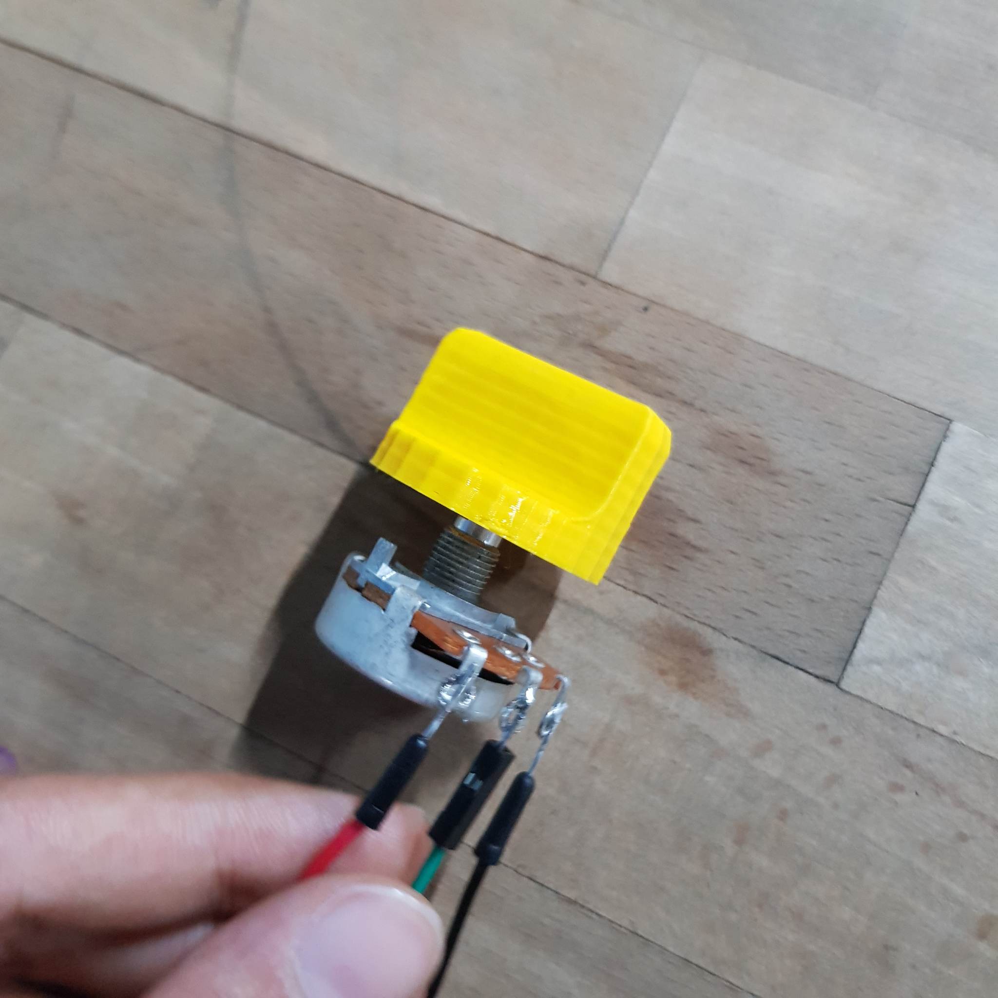
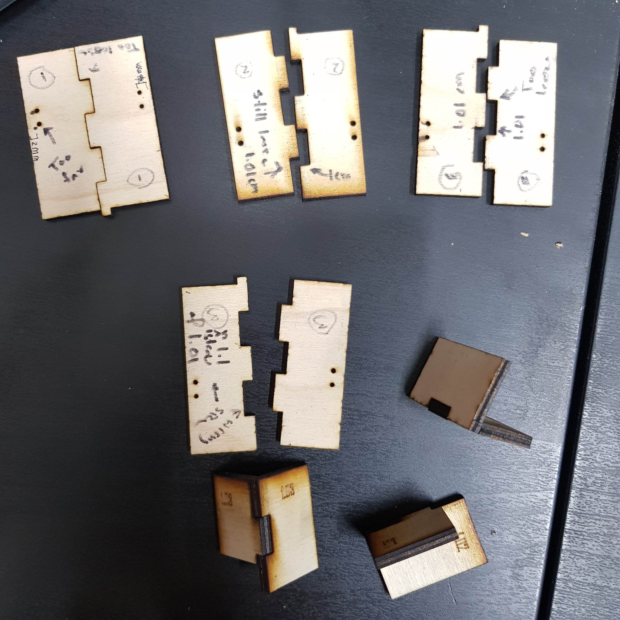
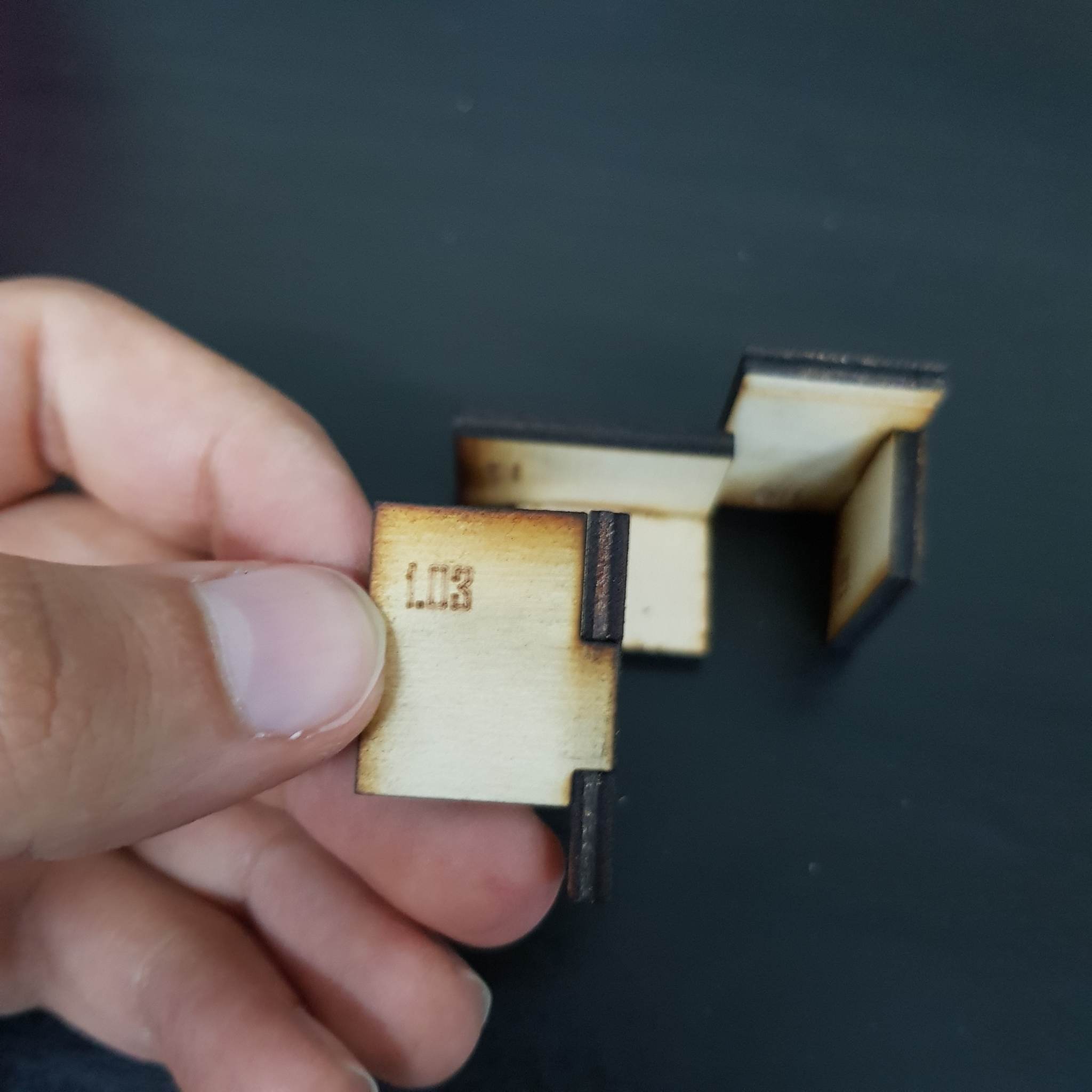
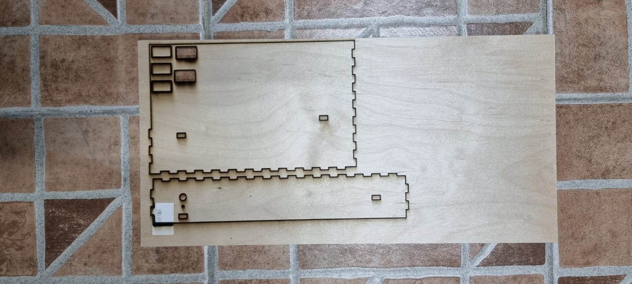
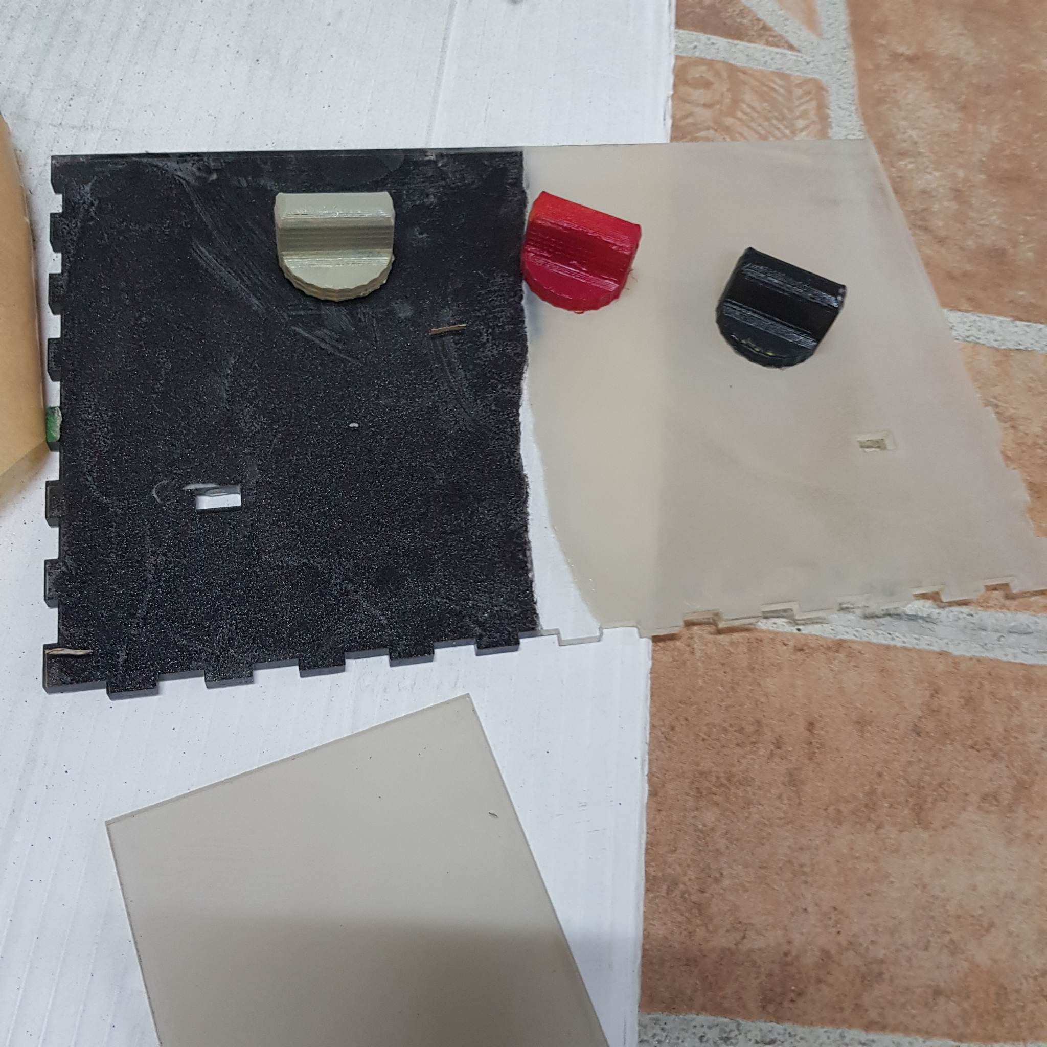
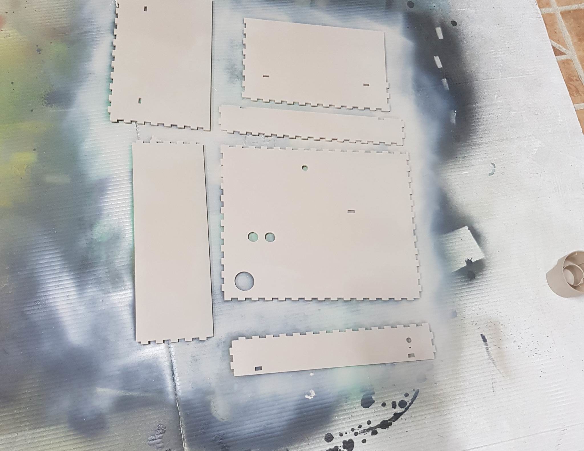
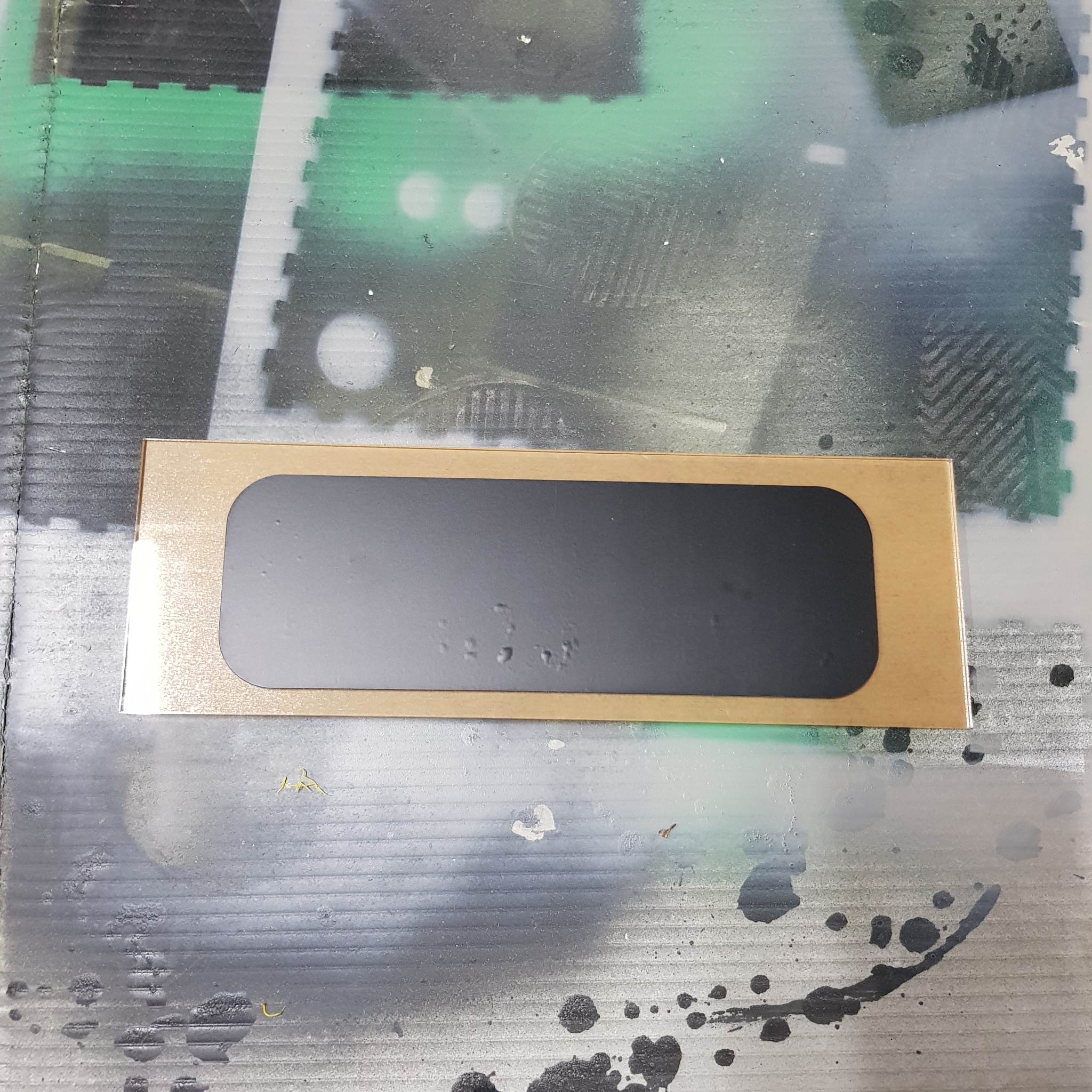
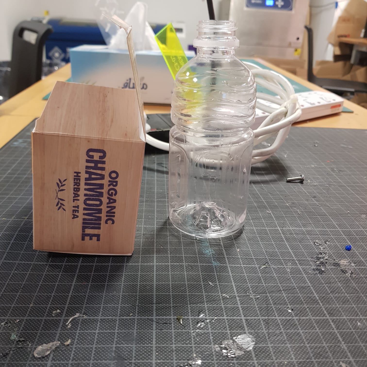
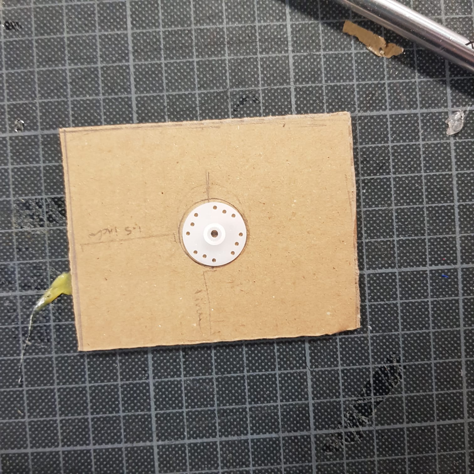
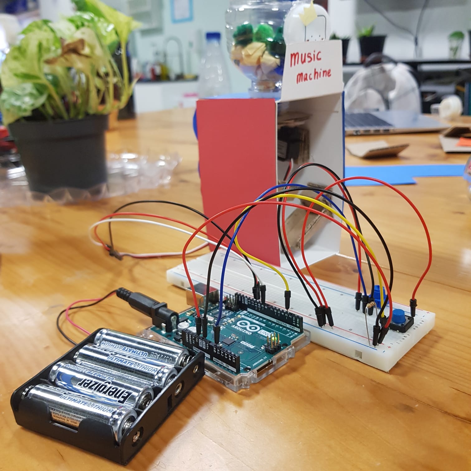
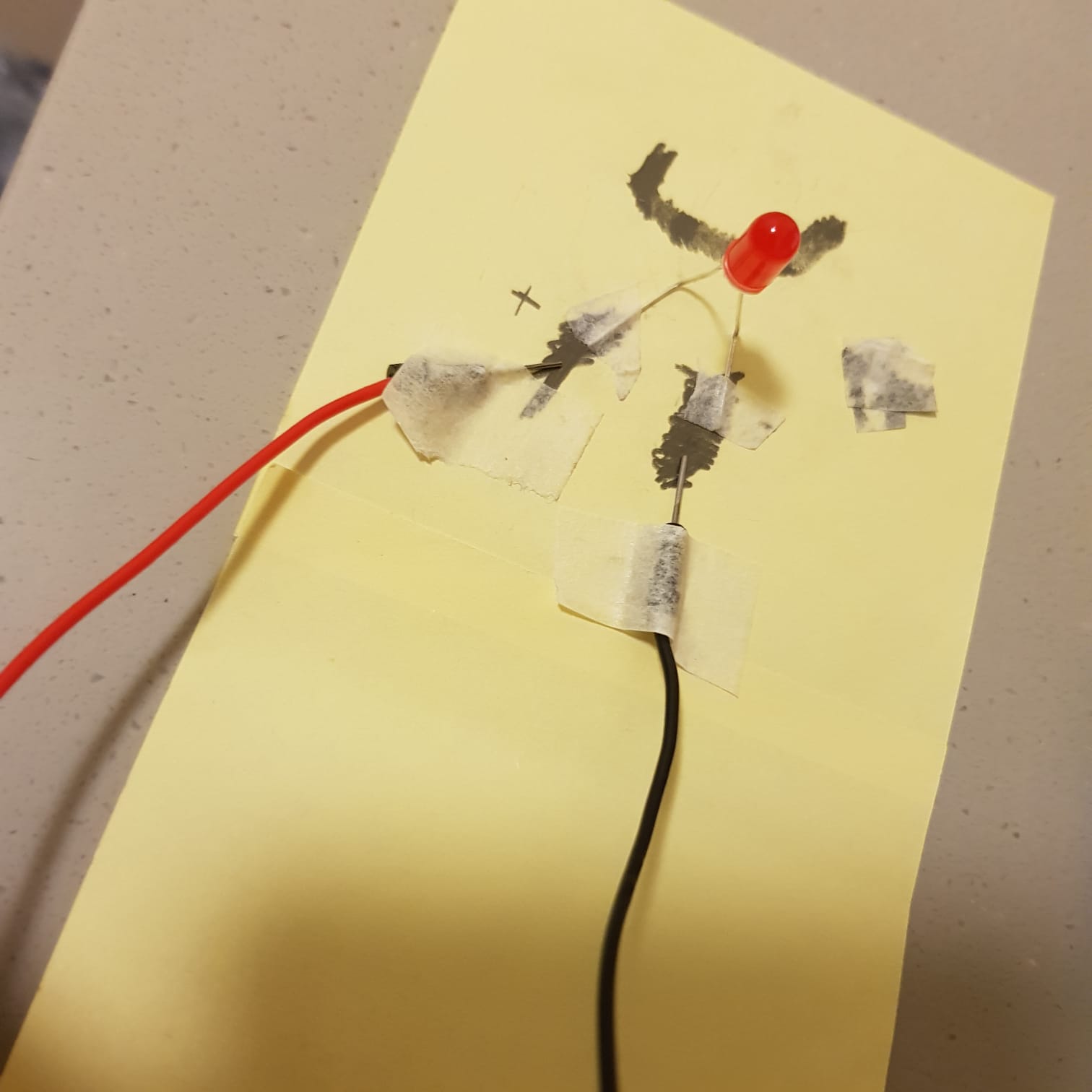
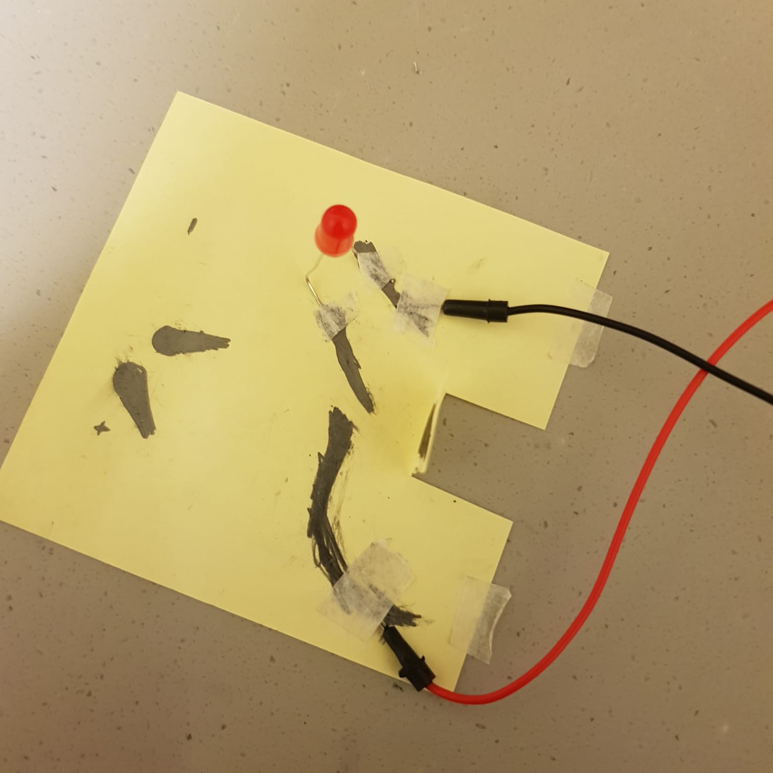
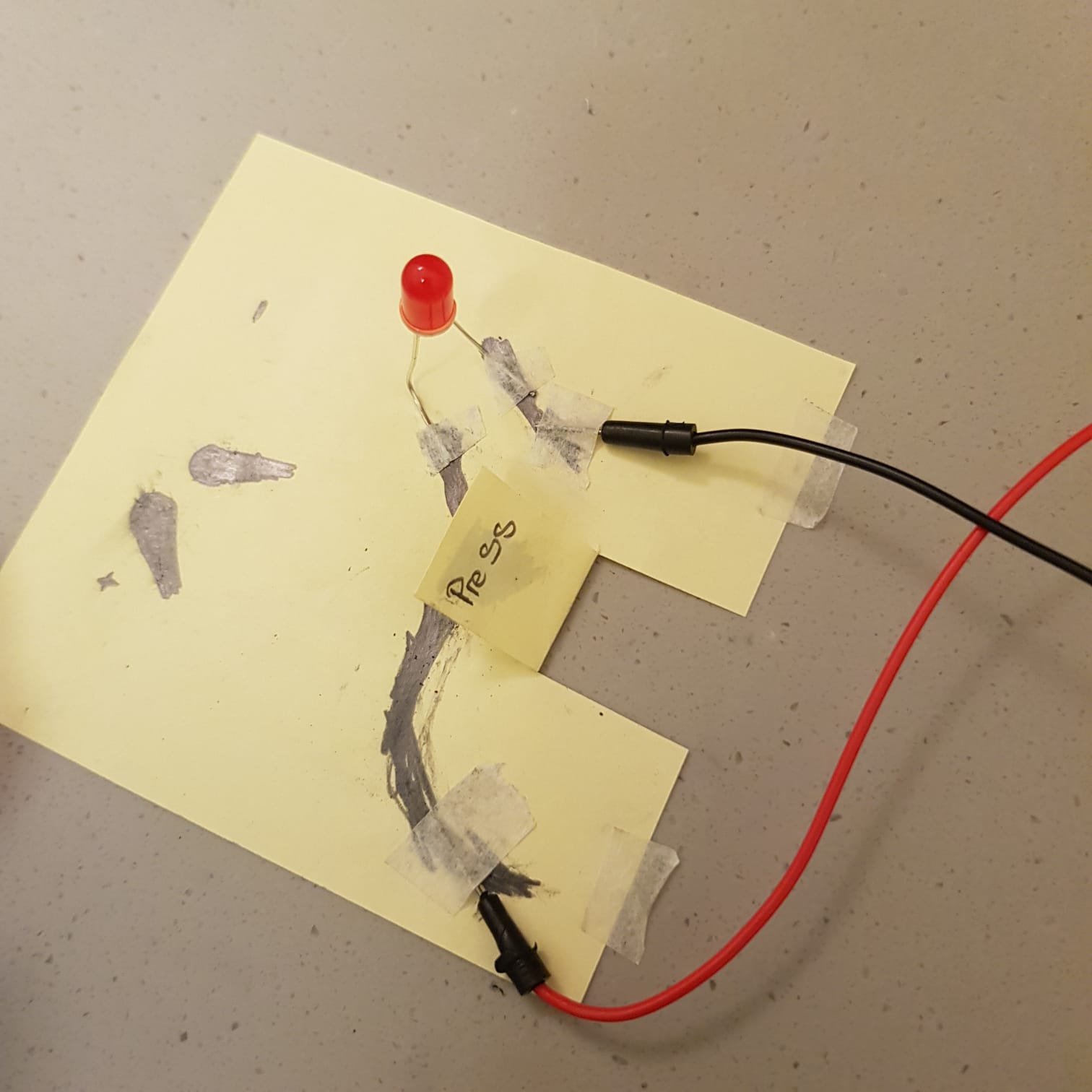
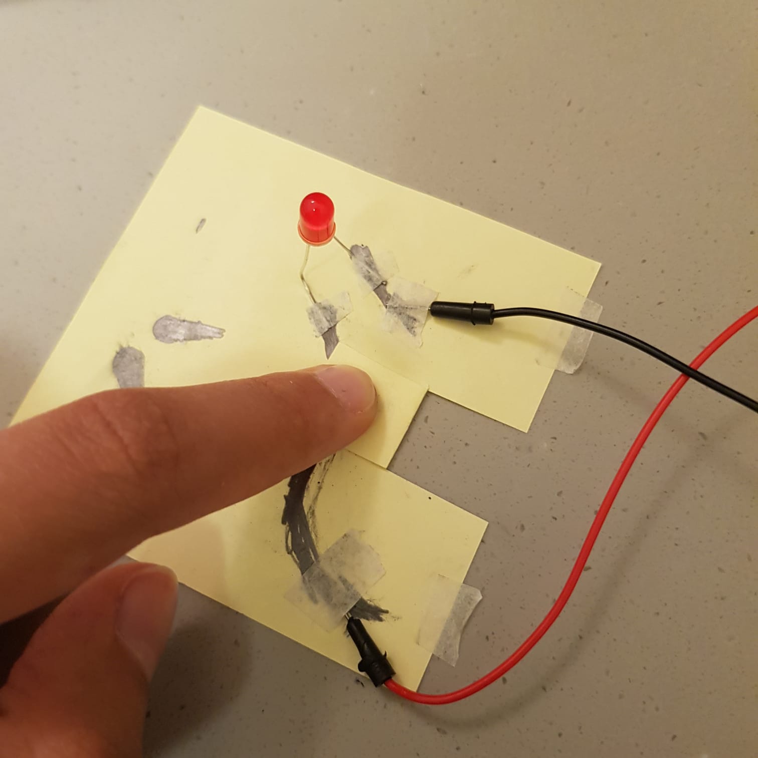
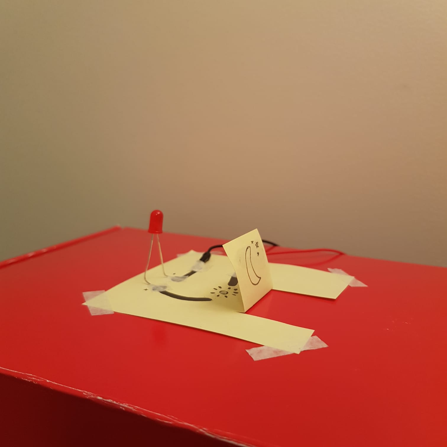
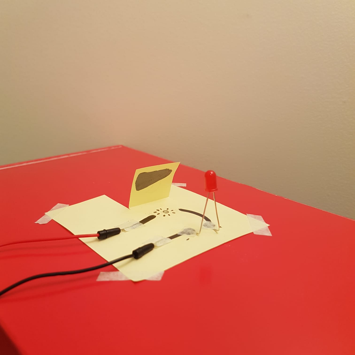
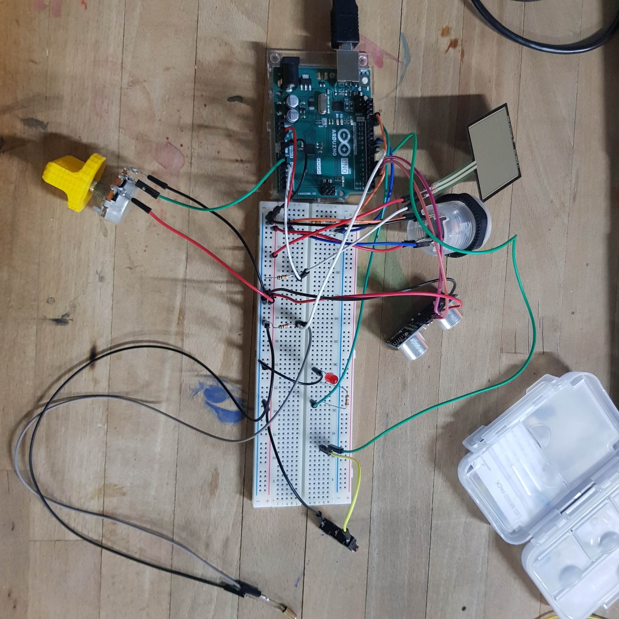
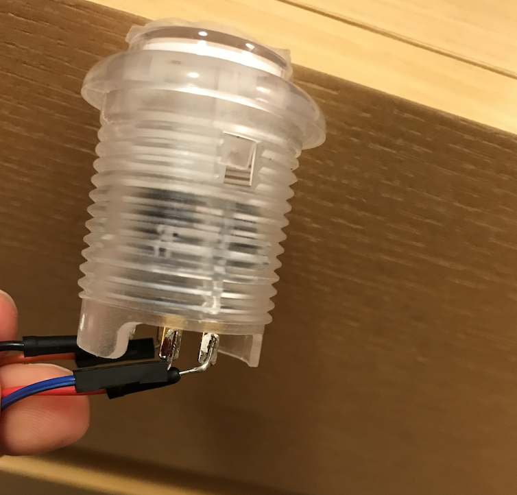
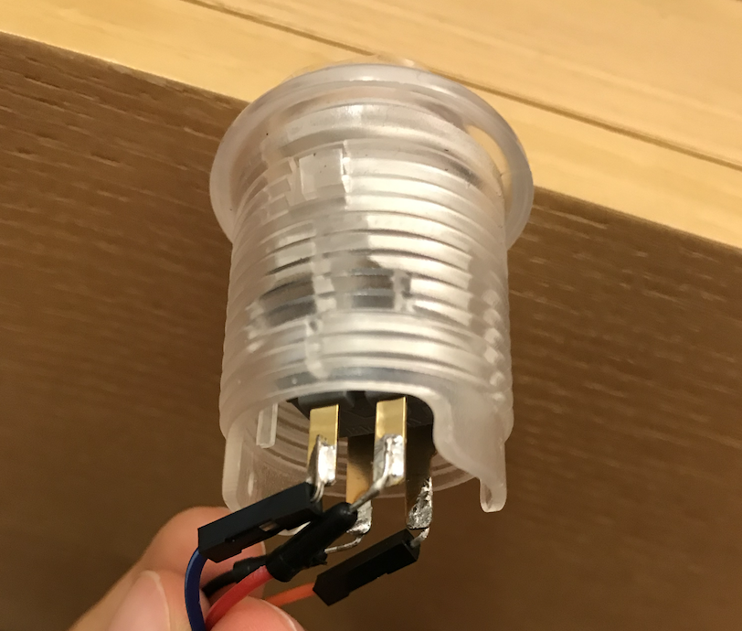
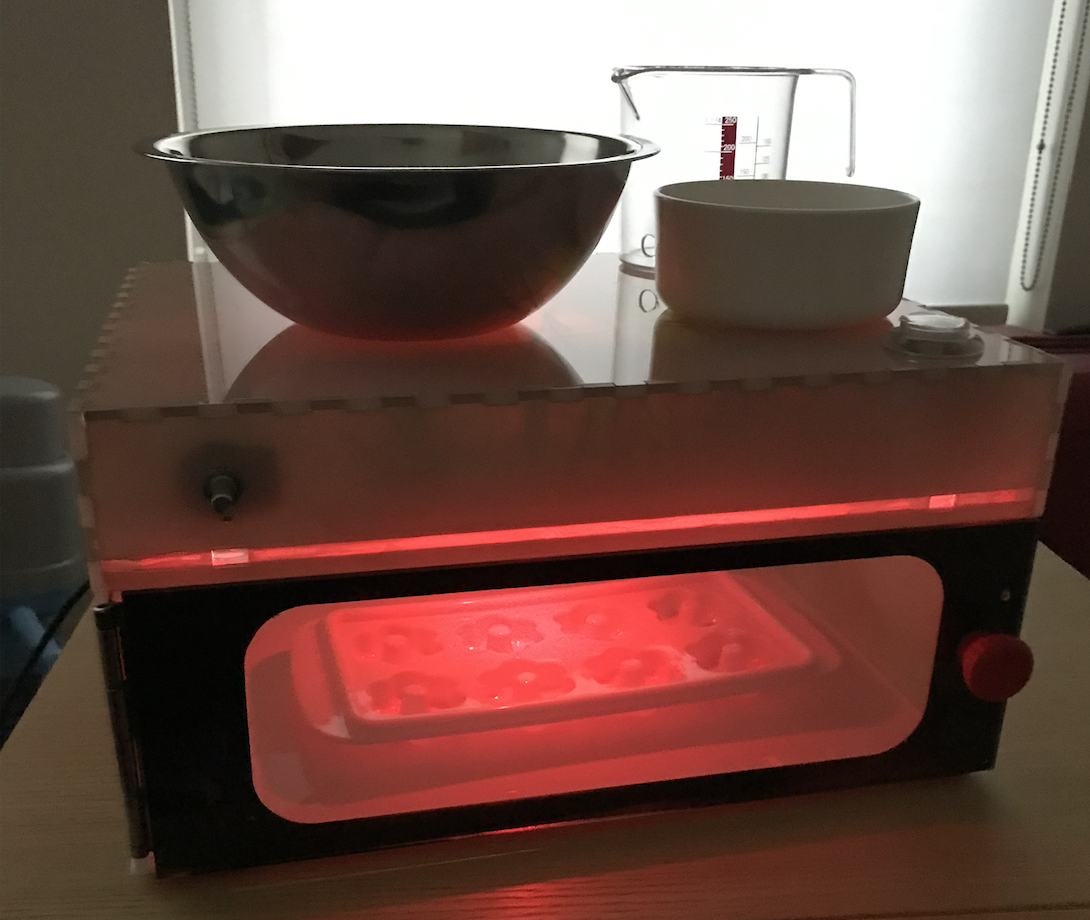
I detailed the arduino process and the creation of the structure that houses it in my previous documentation progress post, but at that point I still havn’t connected the arduino to the structure and it took way longer than I expected. I reorganized the wires and used shorter ones to reduce the clutter and make it easier for me to handle them:
–>
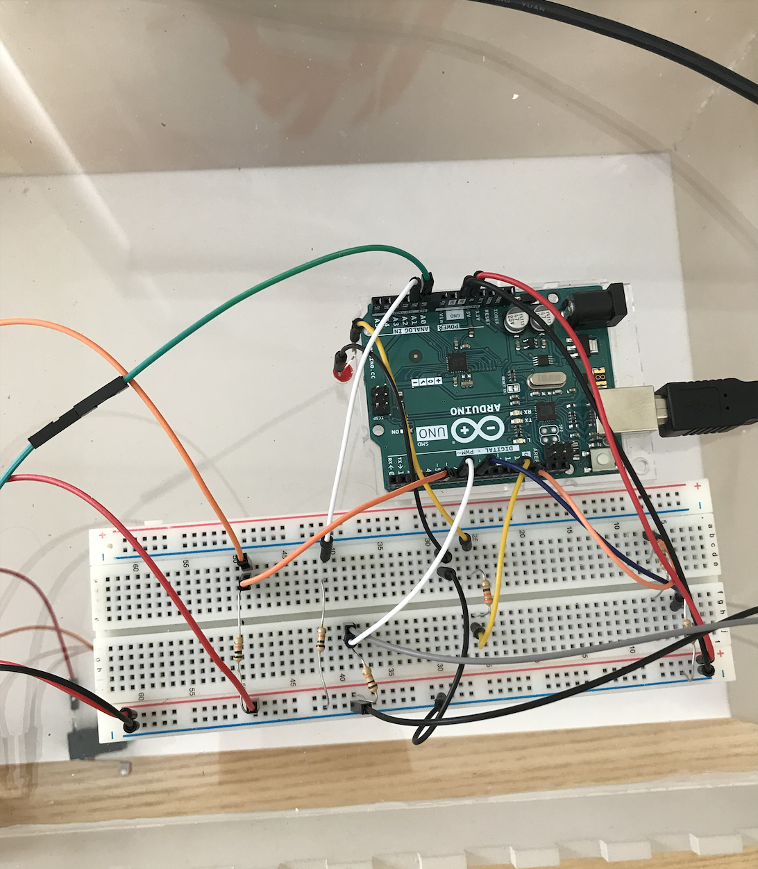
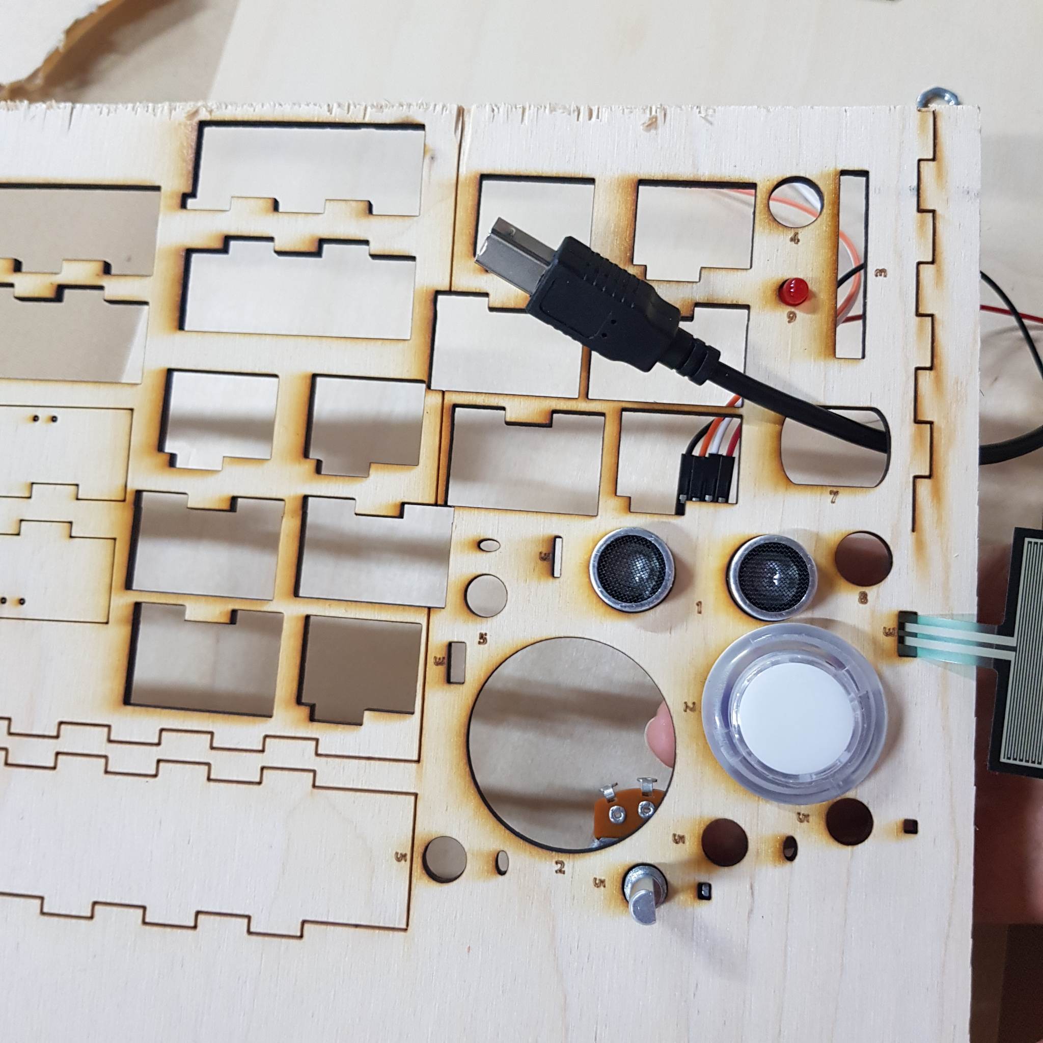
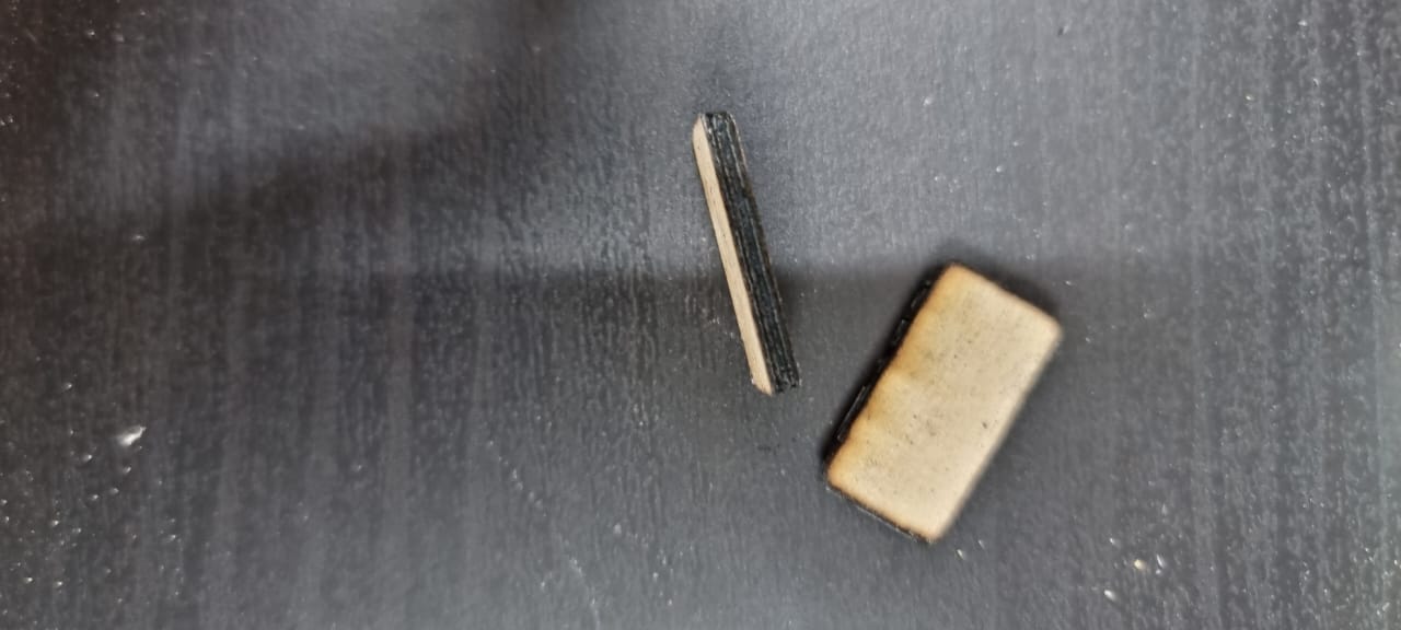
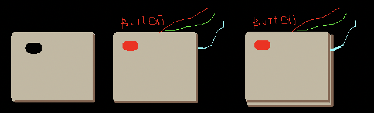
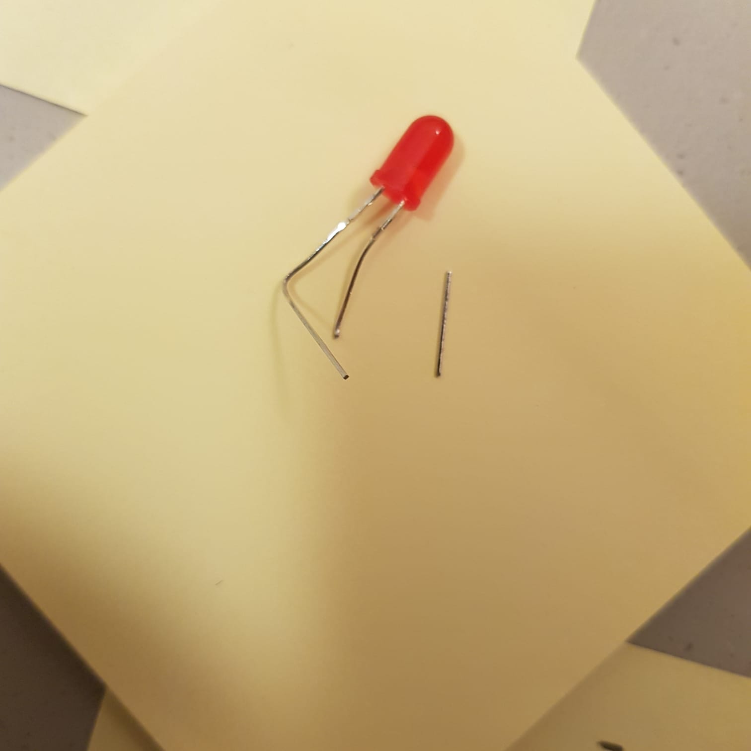
I also realized that my button and the wires soldered to it was too long for the Arduino slot in the structure. I wanted to resolder the wires to the button diagonally so that it fits, but I tried to fold the legs of the LED and it worked and ended up fitting in.
p5.js code
P5js handles all the game screens, logic and mapping of sensor values…etc.
-
- to handle the user running through the pages if the button is continuously pressed I created a “done” variable that is only assigned to true if the user has gone through the page’s task, or if a specific number of frames has gone by.
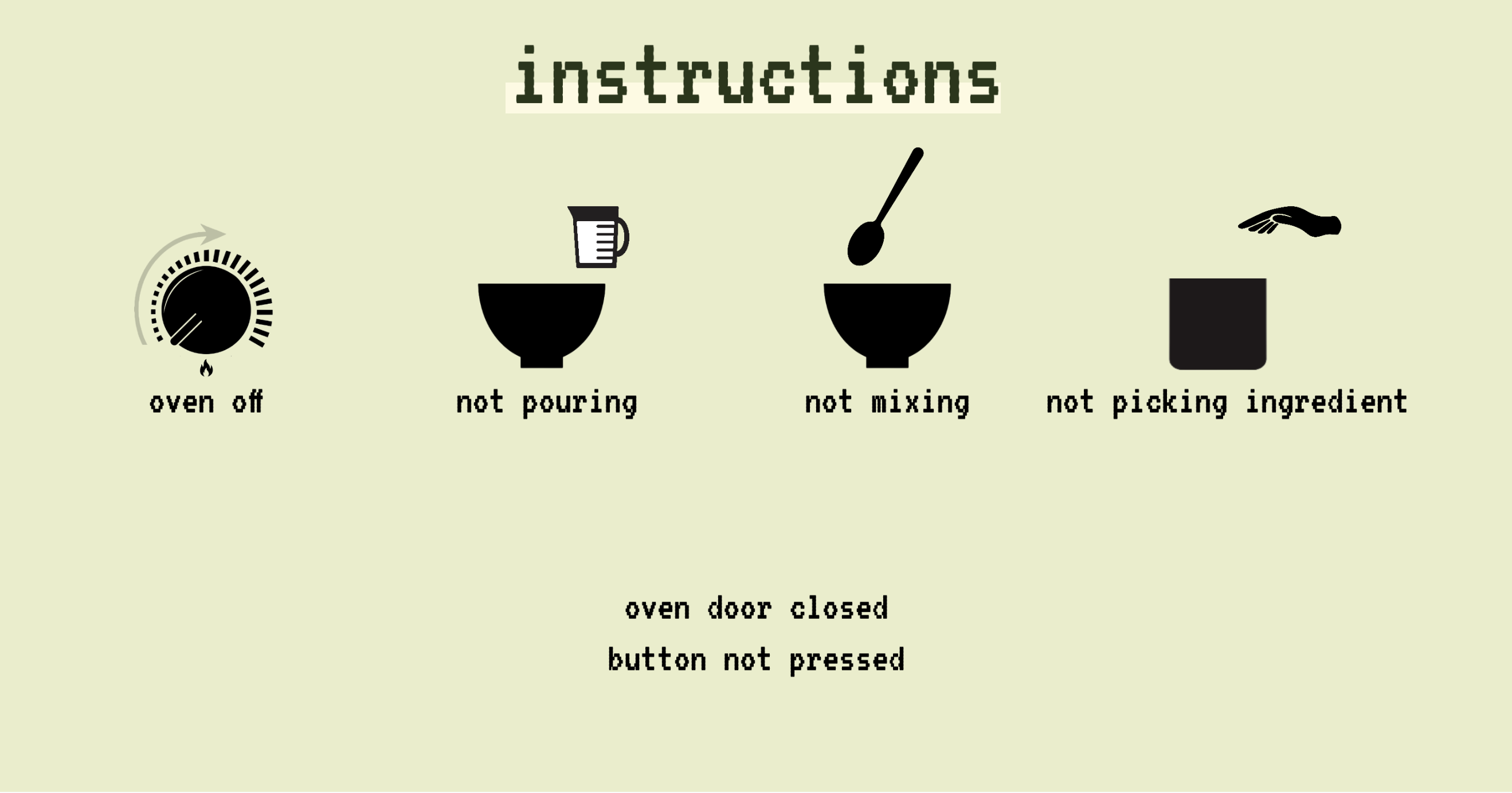
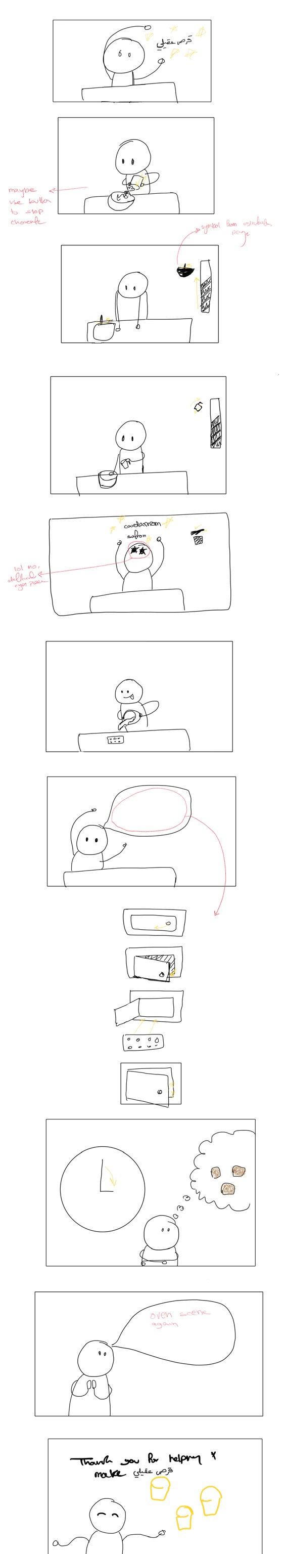
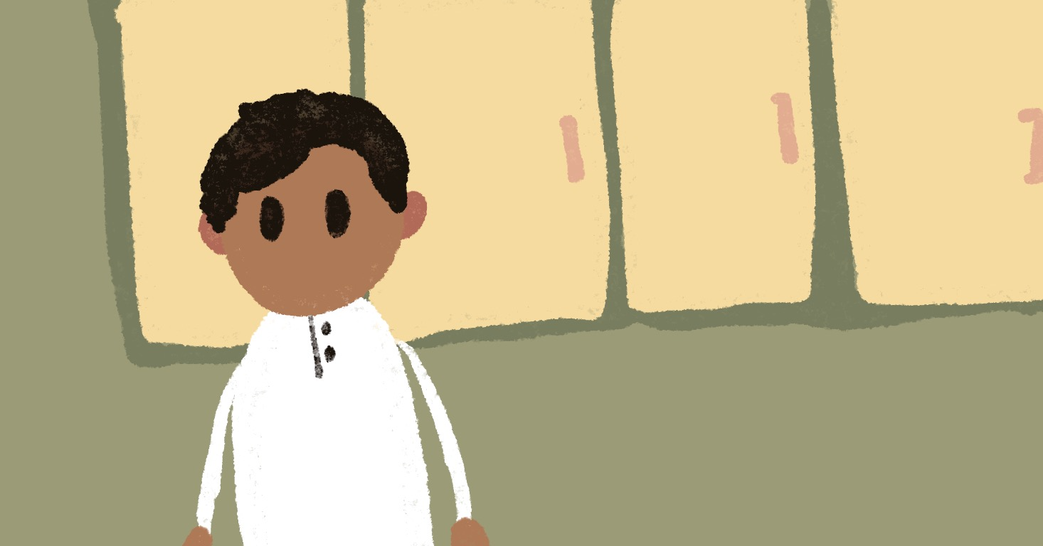
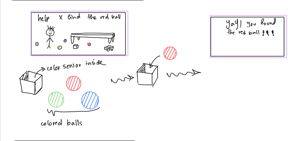
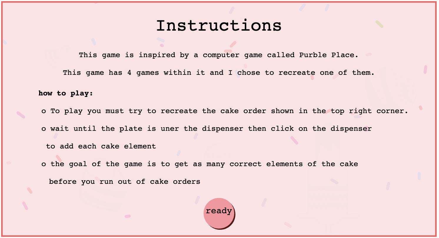
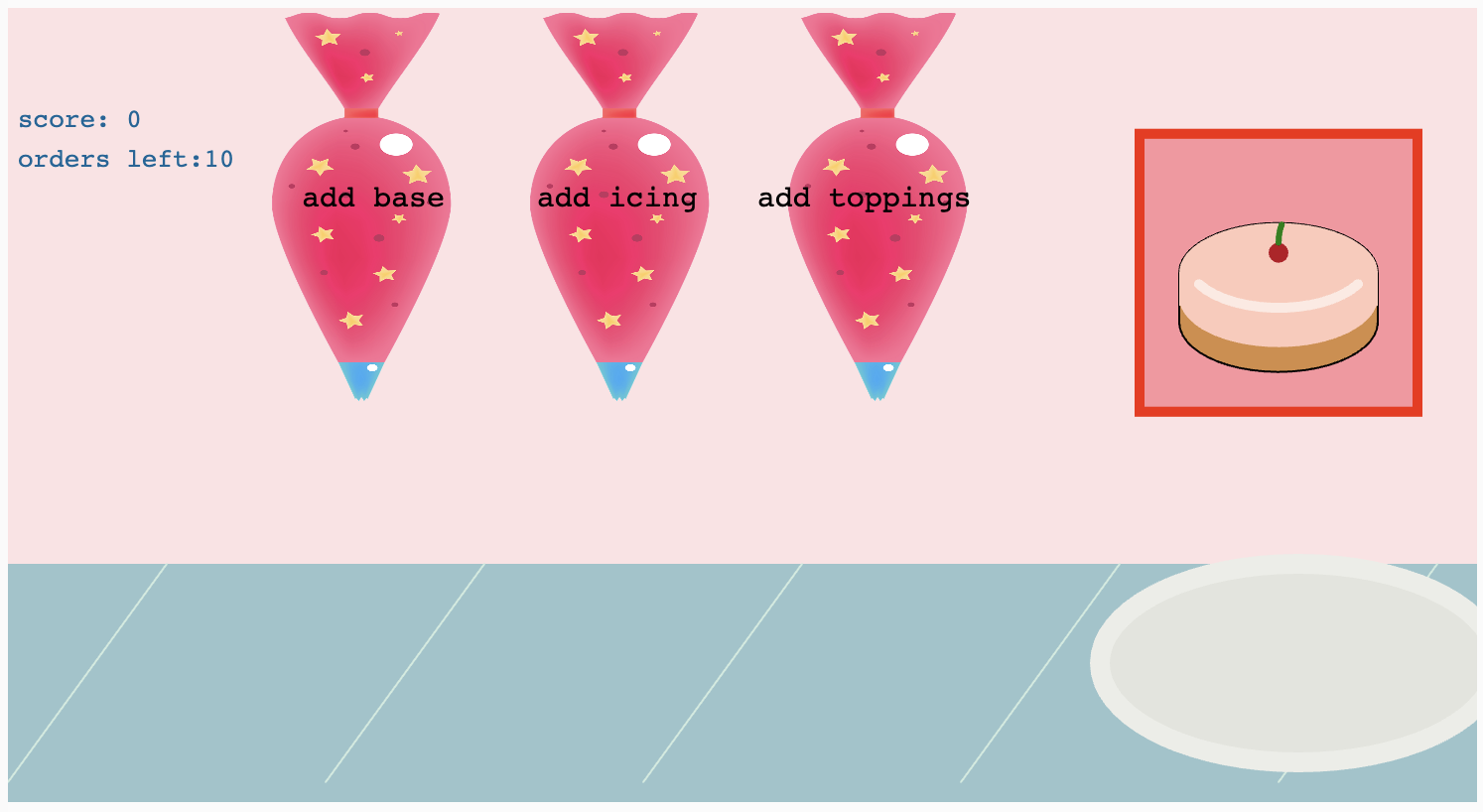
- One challenge was to make the pages as intuitive as possible for a young child. I tried to limit the text in the pages and try to use graphics to indicate what should be done in each page. Someone at the IM showcase suggested using audio that reads out the instructions which I think would be helpful!
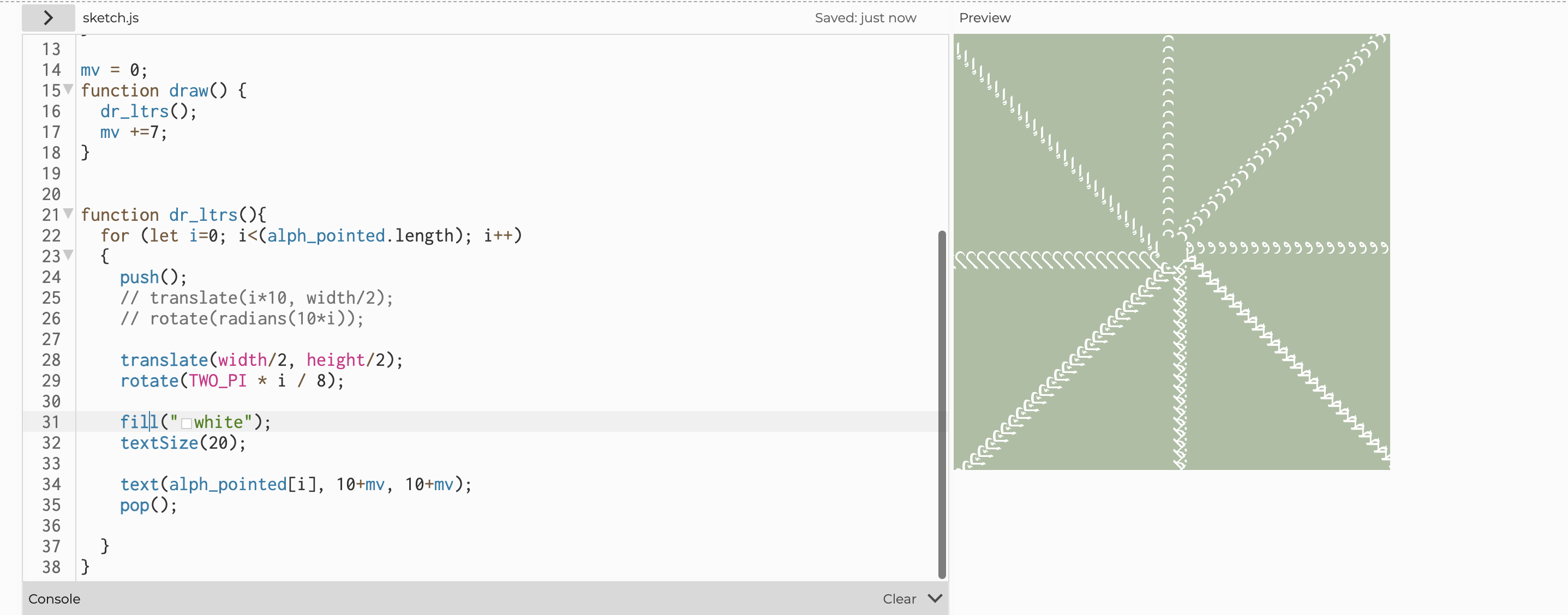
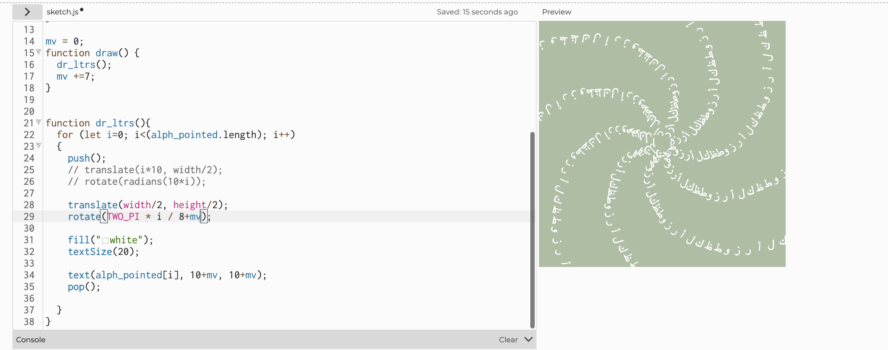
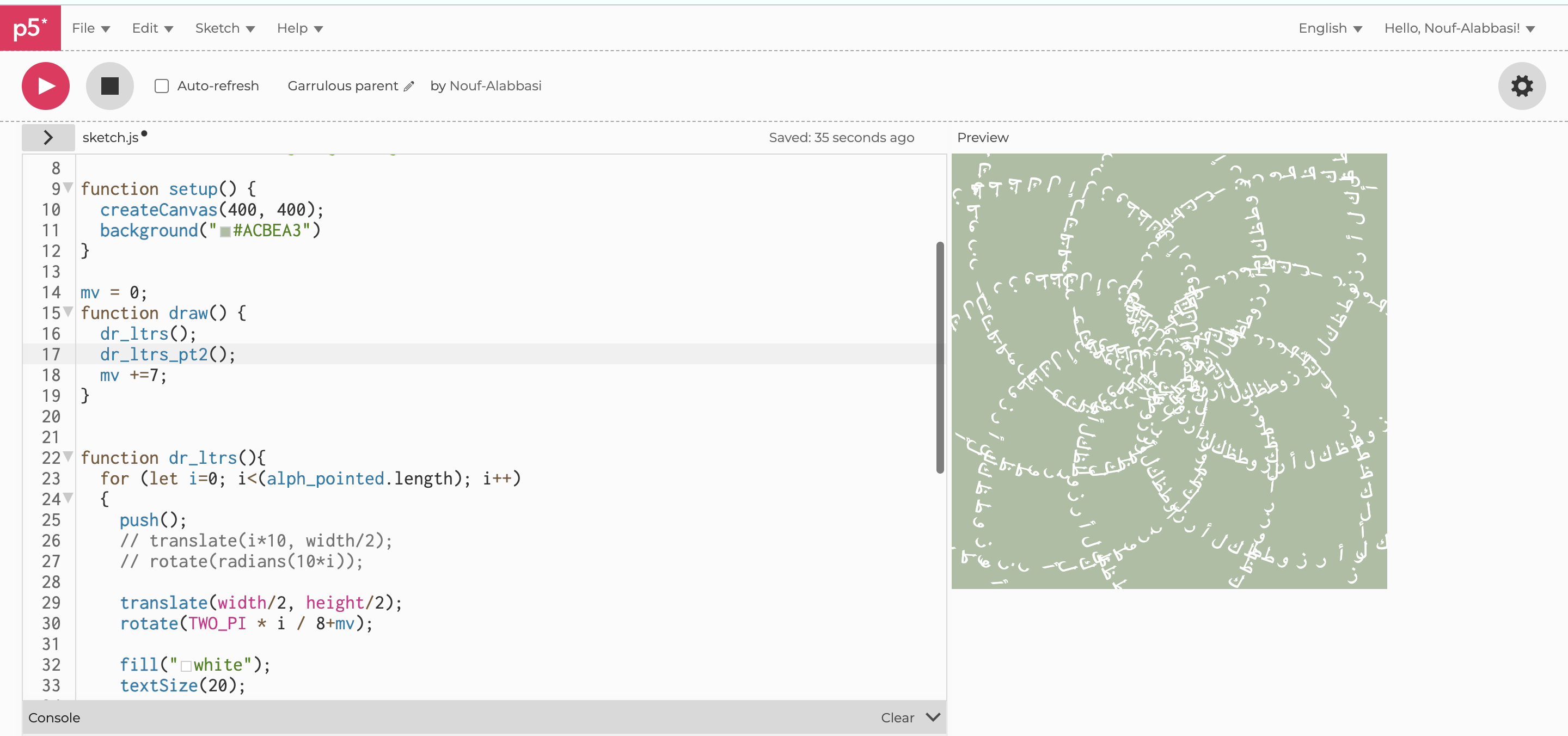
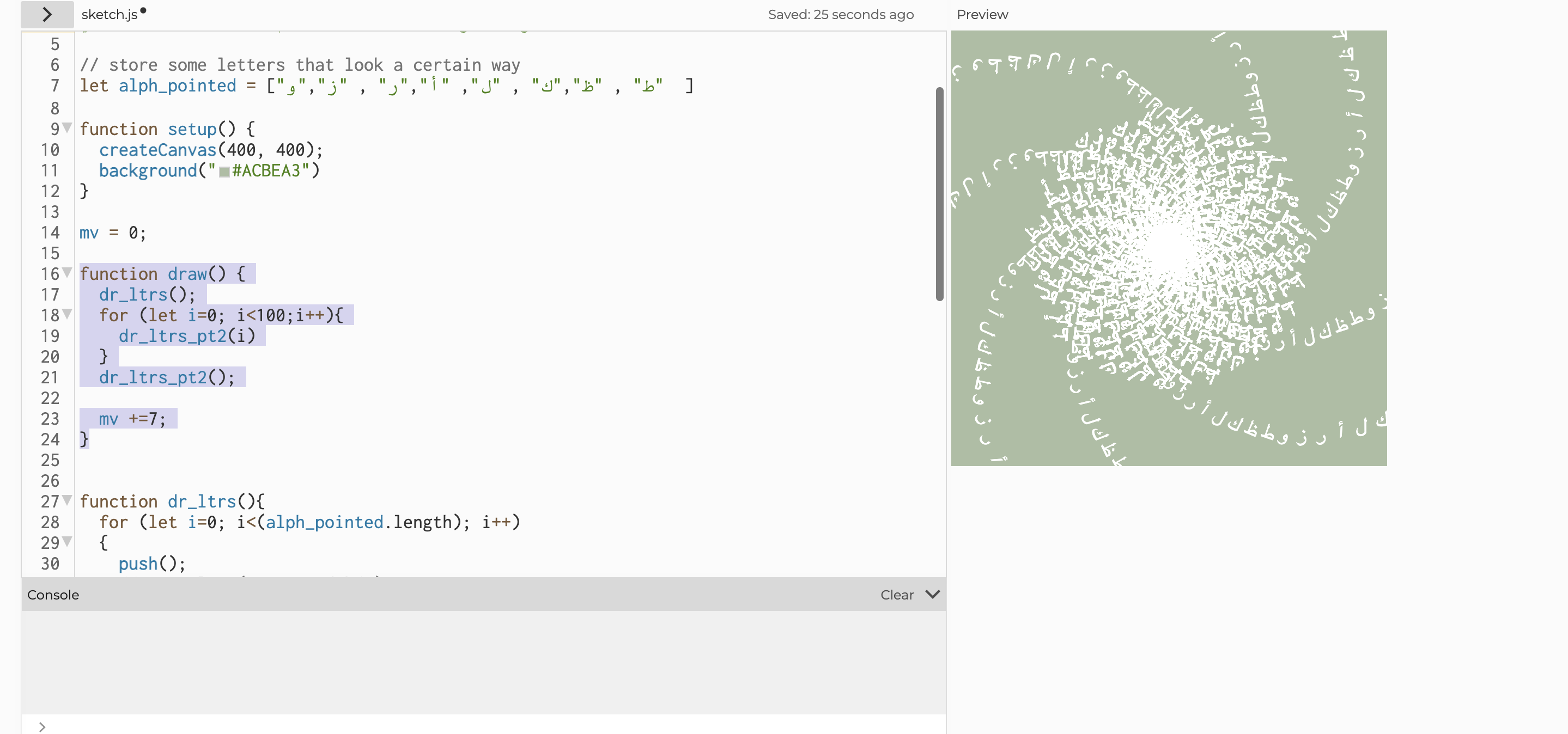
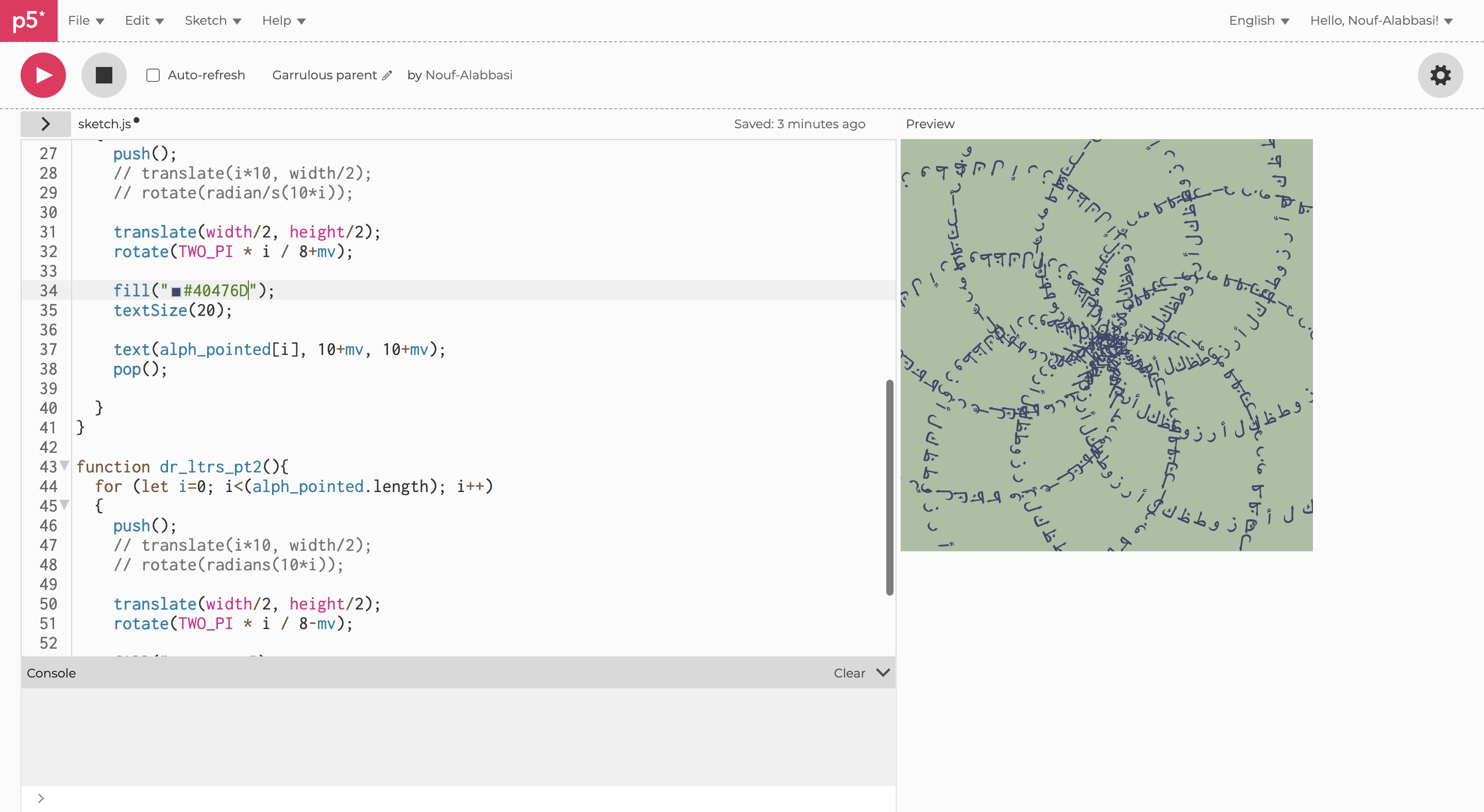
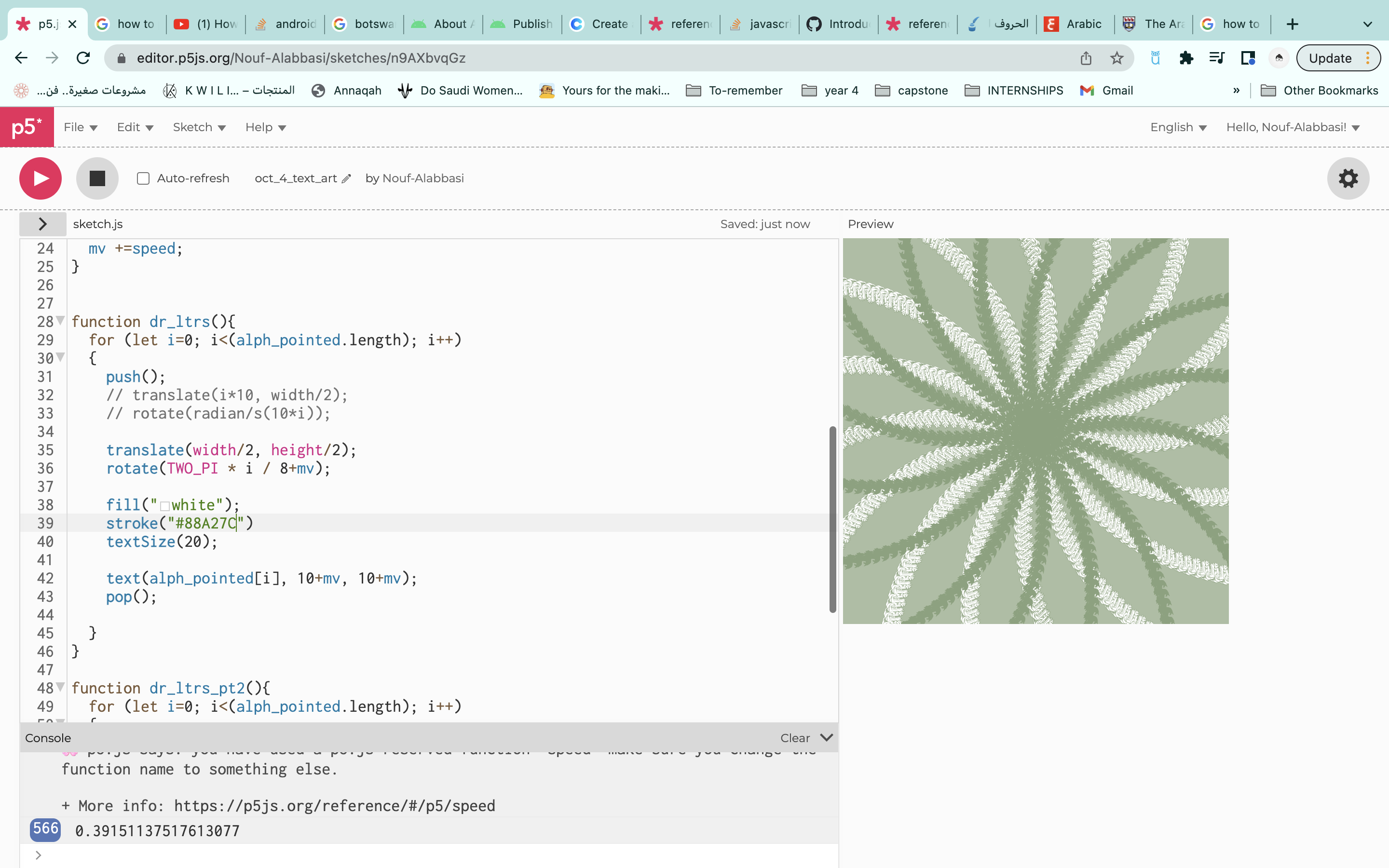
- animation was challenging because I was trying to slow down the switching between img frames. One thing I tried was to slow down the framerate, and then use
framCount%2 ==0however, that also slowed down the button animation. so I tried to use other values in place of the 2 so that, that the img switches every mutliple of 10 for example. but I also wanted the image to be displayed on the screen for a few seconds before being switched again and not only appear for the millisecond where the framecount is a multiple of 10. So I added another if statement that assigns the value of 1 to a variable “other_img” if the framecount is a multiple of 3. if other_img == 1 then the image would be switched.
if (frameCount % 10 == 0)
{
  print(frameCount);
  image(dry_ing_page_2, 0,0);
  other_img = 0;
  if (frameCount%3 == 0)
  {
    image(dry_ing_page_2, 0,0);
    other_img = 1;
  }
}
else{
  if(other_img)
  {
    image(dry_ing_page_1, 0,0);
  }
  else{
    image(dry_ing_page_2, 0,0);
  }
}
-
- I also used a few js files in p5js to organize the code. I had a page for variable definitions, classes, page_functions…ect
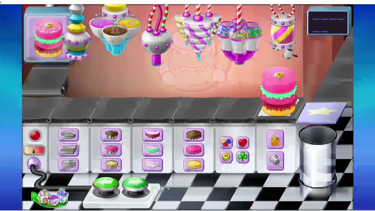
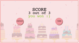
- here are a few of the pages:
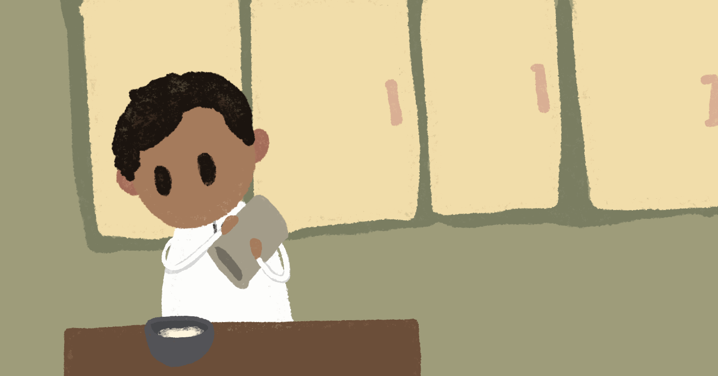
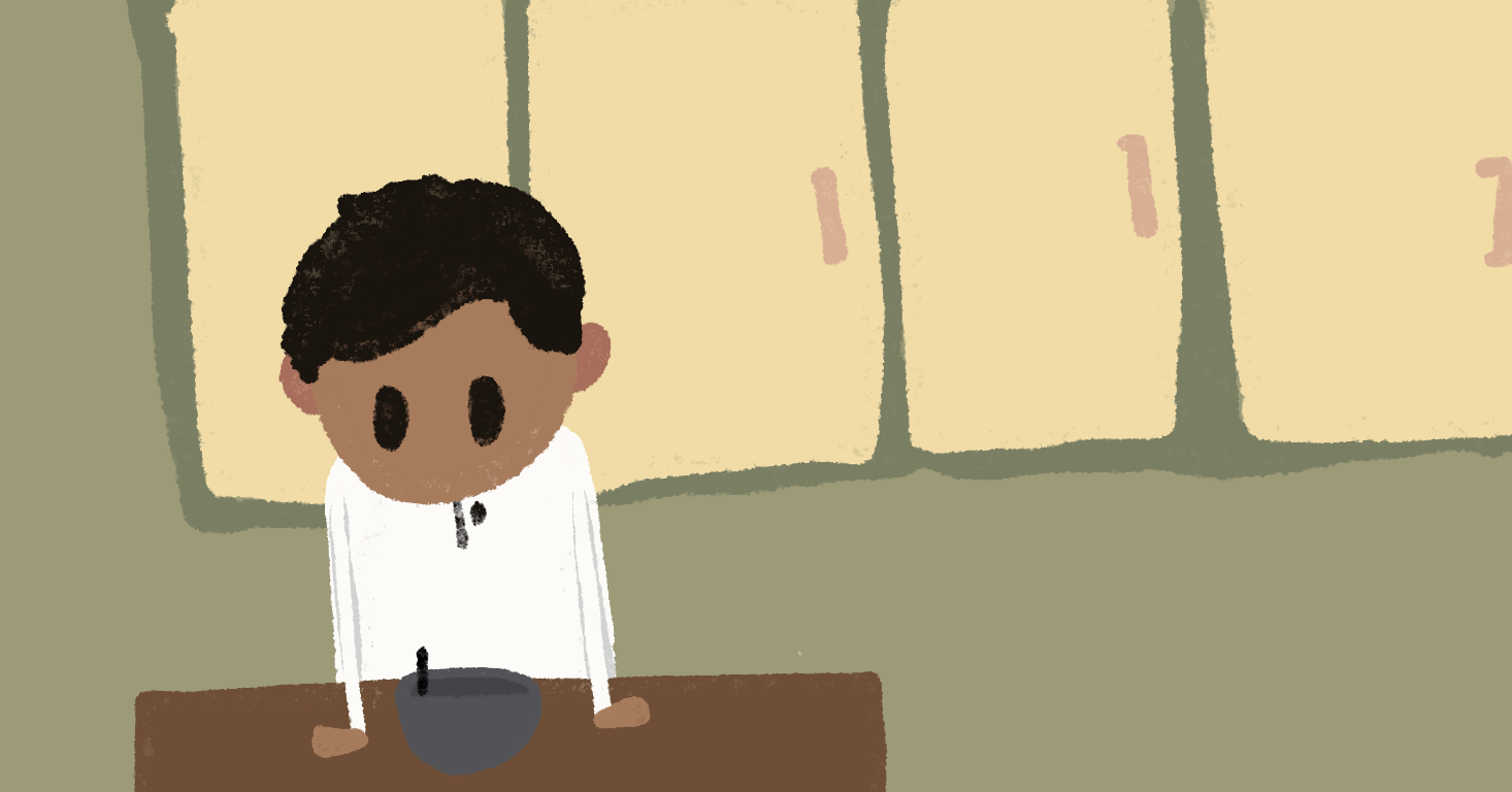
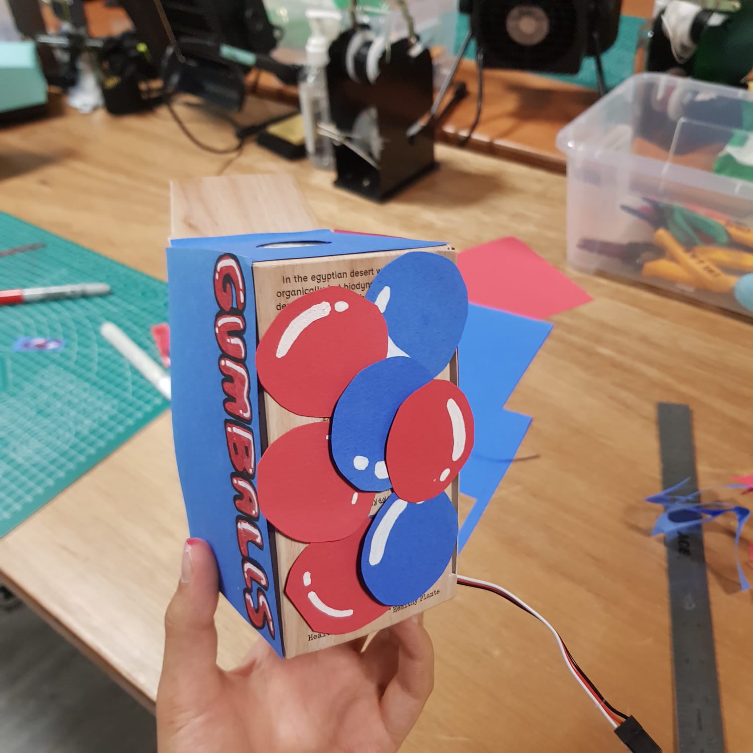
Final project:
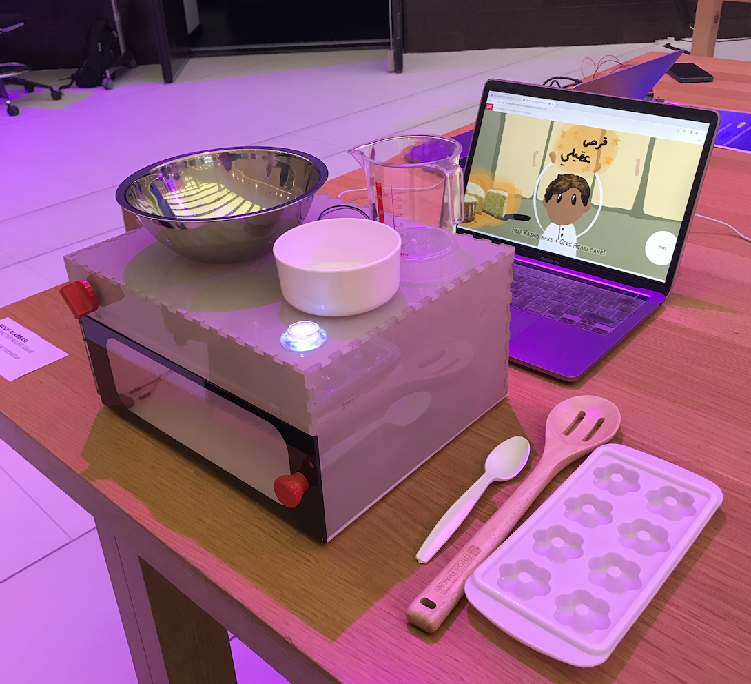
Overall I’m proud of the final project. It turned out a lot neater than I expected.
future improvements
-
- I noticed that sometimes people were unsure what to use for this page’s activity. I think that I could add an LED plate(if that’s a thing) that lights up under the object that needs to be used.
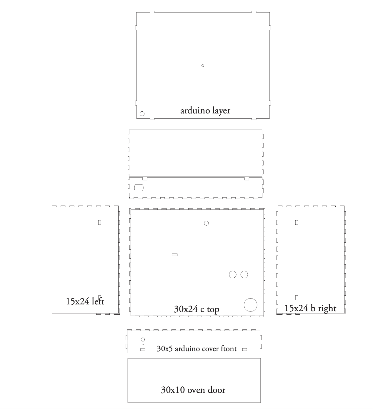
- I think that if I got a chance to redo the structure it would greatly improved
-
- I could the Arduino slot more easily accessible, the back is currently removable to allow me to access the the Arduino when needed but it’s too small
- I’m not sure how this could be solved but the wire attached to the measuring cup is limiting and might not be a good options for kids who might want to move things around freely. I think that there is an Arduino Wi-Fi module but I’m not sure how that would work with the serial connection between the Arduino and p5js and if that is the best solution to get rid of the wire.
-