Final Project Bubble Pop

For the final project, I have created a bubble-popping game that involves both P5.js and Arduino. The main concept is that the user will pop as many bubbles as possible using hand gestures in a playful virtual environment, leveraging hand-tracking technology for a seamless and immersive experience and enjoy real bubble along the way. Initially, the project was supposed to be just a bubble maker that tracked the user and shot bubble at him/her continuously. Unfortunately, due  to technical difficulties, I could not implement that, and after consulting with the professor, I decided to make a game instead.

How it works:

The user comes in front of the camera and raises his/her left hand. If the camera detects left hand raised on the left side of the screen (the right side by mirroring), the bubble starts to generate in the middle portion of the screen, and a timer gets started. The timer is set to 2 minutes of maximum time. Then the user will pop the bubbles with the finger tips by making popping a bubble gesture. Users get points for popping the bubble based on the popped bubble’s size. And if the user want, he/she can quit the game by raising his/her hand. While the game is on and the user scores cross a milestone, a signal is sent to the Arduino to turn on the servo motor and a DC motor fan. Servo takes the bubble-making stick in front of the fan and generates bubbles.  The servo and the fan will keep generating bubbles while the game is on. Initially, I had 400 points (400, 800, 1200, … )  as milestones. However, after user testing, I reduced it to 100. So, after every 100 points, you get bubbles. The reasoning behind this was that all the users were more into the actual bubble popping experience and all wanted to get more real bubbles while playing the game. A This  gives the user a more immersive bubble-popping experience, as from time to time they can pop the real bubbles too. During the gameplay the user can press “H” on the keyboard for the instructions. The game also keeps track of high scores and has a 2 minutes timer.

User testing:

After user testing, I made few changes. I had 2 user tests. During my initial testing, I received feedback to make the real bubble generation a reward for popping the on screen bubbles, which currently implemented in the game. And during my second user test, the user told me to make it a bit easier to get real bubbles. I have reduced the milestone from 400 to 100 afterwards. Other than this, I received reviews from the Professor. One was to make the on-screen bubble bigger and more visible (opacity). The second was to incorporate visuals and instructions. Both have been implemented in the game.
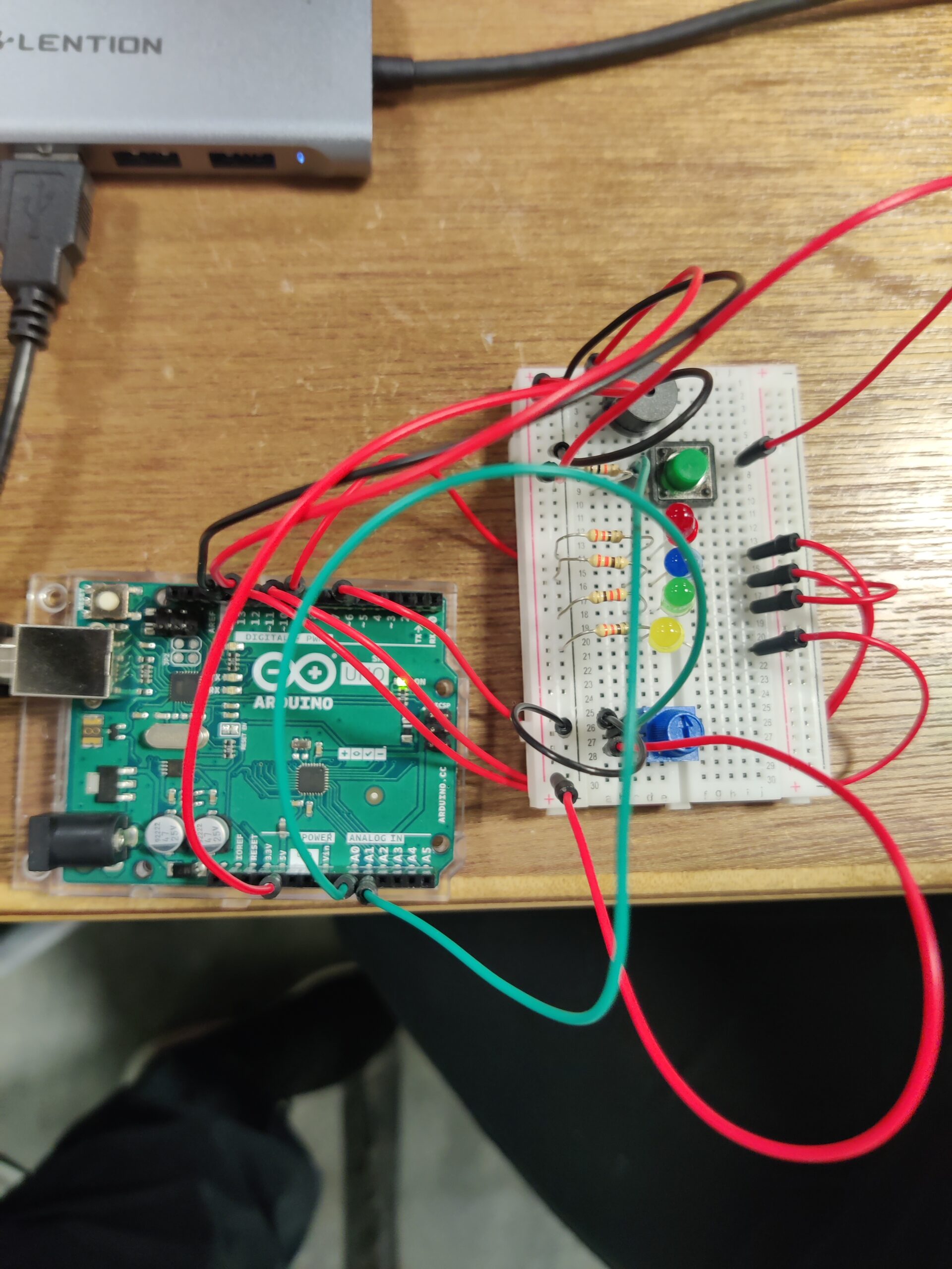
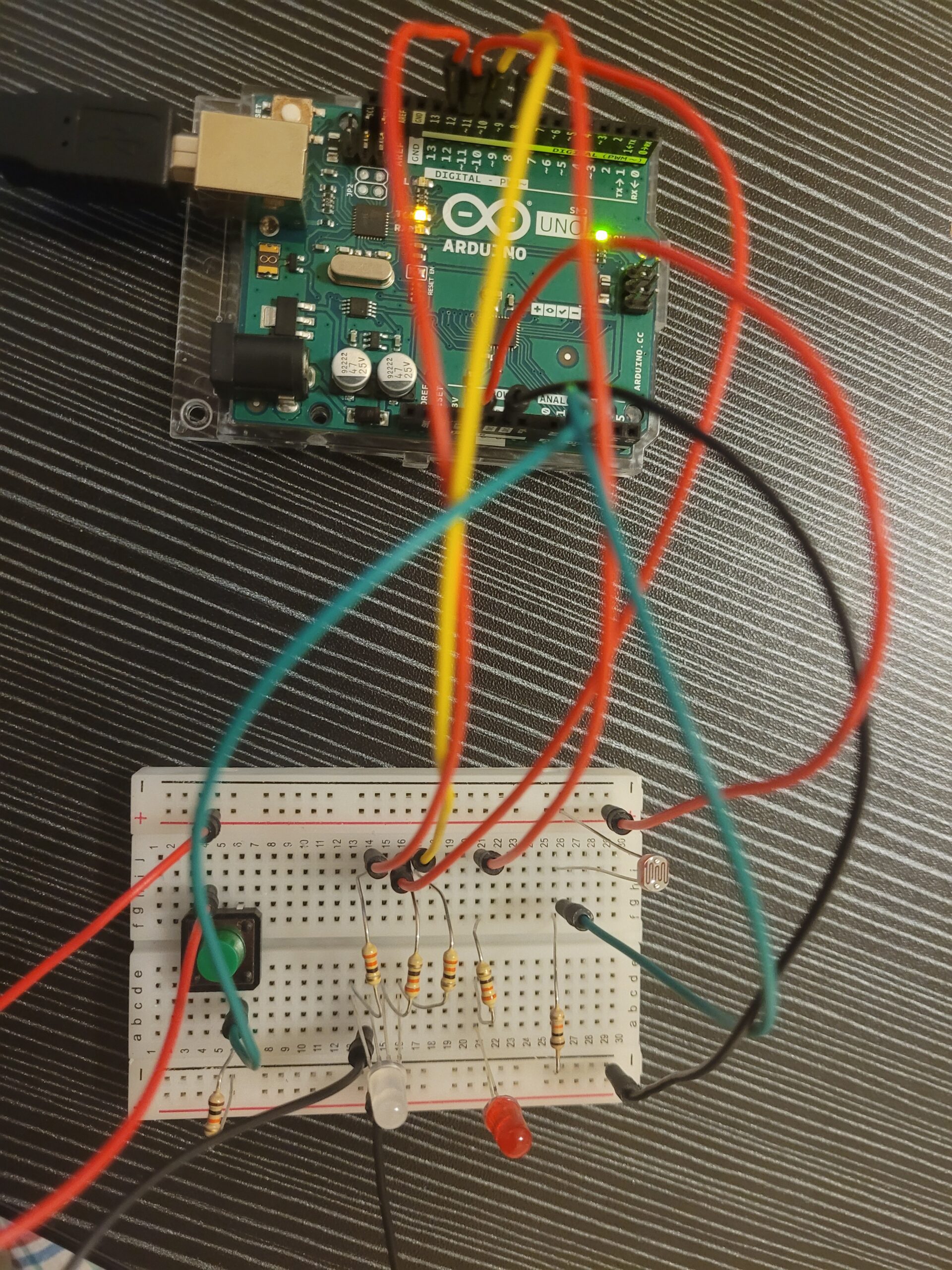
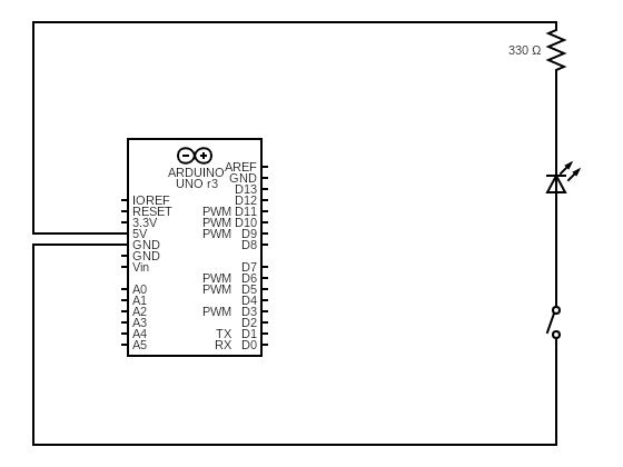
Schematic:

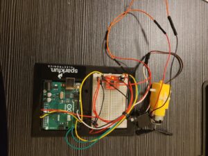
As the tinkercad did not have the SparkFun Motor Driver – Dual TB6612FNG (1A) used in the project, the schematic has been adjusted for L293D Motor Driver.


P5.js Code:

Serial communication is needed to run the game. The cover picture was made using DALL-E 2.

In this game, hand detection is accomplished using the ml5.handpose model. This model detects 21 hand keypoints representing different parts of the hand. Each keypoint provides an x, y, and z coordinate, but here, only the x and y coordinates are used. These keypoints are used to detect gestures and interact with the game objects (bubbles).

Gestures are detected based on the position of keypoints of all five fingers. Here’s how gestures to start and stop the game are handled:

const LEFT_FINGERS = [4, 8, 12, 16, 20]; // Indices of the left-hand finger tips
let play = 0; // 0 for paused, 1 for playing
let waveTimeout = null;
let waveCooldown = false;
let leftBoundary, rightBoundary;
let scaleX, scaleY;
let videoWidth = 640;
let videoHeight = 480;

function detectHandGesture() {
  if (hands.length > 0) {
    const fingerIndices = [4, 8, 12, 16, 20]; // Thumb, index, middle, ring, pinky tips
    let allInLeft = true;
    let allInRight = true;

    for (let index of fingerIndices) {
      let x = (videoWidth - hands[0].keypoints[index].x) * scaleX;
      if (x < leftBoundary) {
        allInRight = false;
      } else if (x > rightBoundary) {
        allInLeft = false;
      } else {
        allInLeft = false;
        allInRight = false;
      }
    }

    if (allInLeft && play === 0) {
      togglePlayState(1); // Start playing
    } else if (allInRight && play === 1) {
      togglePlayState(0); // Stop playing
    }
  }
}

function togglePlayState(newState) {
  play = newState;
  waveCooldown = true;

  if (play === 1) {
    startTime = millis(); // Start the timer when playing starts
  } else {
    updateHighScore(); // Update high score before resetting
    resetGame();
  }

  waveTimeout = setTimeout(() => {
    waveCooldown = false;
  }, 3000); // Add a 3-second cooldown to prevent repeated triggering
}
function drawBubbles() {
  let leftFingers = [];
  if (hands.length > 0) {
    let hand = hands[0];
    for (let index of LEFT_FINGERS) {
      let keypoint = hand.keypoints[index];
      leftFingers.push({
        x: (videoWidth - keypoint.x) * scaleX,
        y: keypoint.y * scaleY,
      });
    }
  }

  for (let i = 0; i < bubbles.length; i++) {
    let bubble = bubbles[i];
    fill(bubble.color[0], bubble.color[1], bubble.color[2], 100);
    noStroke();
    ellipse(bubble.x, bubble.y, bubble.size * 5, bubble.size * 5);

    bubble.x += bubble.speedX;
    bubble.y += bubble.speedY;
    bubble.x = constrain(bubble.x, leftBoundary, rightBoundary);

    // Check for collision with any of the left fingers and pop the bubble
    if (play === 1) {
      for (let finger of leftFingers) {
        if (dist(bubble.x, bubble.y, finger.x, finger.y) < bubble.size * 2.5) {
          bubbles.splice(i, 1);
          popped.play();
          score += floor(bubble.size / 2);
          i--;
          break;
        }
      }
    }
  }
}

The left-hand finger tips are used to pop bubbles.

The readSerial function communicates with an Arduino device by sending signals based on the player’s score. The function first initializes a milestone at 100, representing the initial target score. When the function is called with new data, it checks whether the player’s score has reached or surpassed this milestone. If the score meets or exceeds the milestone, it sends a signal to the Arduino to keep the game state active (play is set to 1) and then increments the milestone by 100 for the next target. If the score is below the milestone, it sends a signal to the Arduino to deactivate the game state (play is set to 0). The function ensures that the Arduino receives real-time feedback on the game’s progress, controlling external devices or triggers accordingly.

let milestone = 100; // Initialize the first milestone
function readSerial(data) {
  if (data != null && score != 0) {
    let sendToArduino;

    // If the score has crossed the milestone, keep `play` as 1
    if (score >= milestone) {
      sendToArduino = play + "\n";
      // Update to the next milestone (e.g., 100 to 200, 300 to 400, etc.)
      milestone += 100;
    } else {
      // Otherwise, set `play` to 0
      sendToArduino = "0\n";
    }

    writeSerial(sendToArduino);
  }
}


Arduino Code:
#include <Servo.h>

Servo myservo1;
Servo myservo2;
Servo myservo3;

int pos = 45;
int play = 0;
int high = 25;
int low = 85;

const int ain1Pin = 3;
const int ain2Pin = 4;
const int pwmAPin = 5;


void setup() {
  myservo1.attach(8);
  myservo2.attach(9);
  myservo3.attach(10);

  pinMode(ain1Pin, OUTPUT);
  pinMode(ain2Pin, OUTPUT);
  pinMode(pwmAPin, OUTPUT);

  Serial.begin(9600);
  while (Serial.available() <= 0) {
    digitalWrite(LED_BUILTIN, HIGH);
    Serial.println("0,0");
    delay(200);
    digitalWrite(LED_BUILTIN, LOW);
    delay(50);
  }
}

void loop() {
  while (Serial.available()) {
    play = Serial.parseInt();
    if (play && Serial.read() == '\n') {
      myservo1.write(45);
      myservo2.write(45);
      moveServoSlowly(myservo3, low, high, 20);
      analogWrite(pwmAPin, 255);
      digitalWrite(ain1Pin, HIGH);
      digitalWrite(ain2Pin, LOW);
      delay(3000);
      analogWrite(pwmAPin, 0);
      moveServoSlowly(myservo3, high, low, 20);
      delay(2000);
    }
    Serial.println(1);
  }
}

void moveServoSlowly(Servo &servo, int startPos, int endPos, int stepDelay) {
  int step = startPos < endPos ? 1 : -1;
  for (int pos = startPos; pos != endPos; pos += step) {
    servo.write(pos);
    delay(stepDelay);
  }
  servo.write(endPos);
}

I initially had issues with my servo motor movement. It was moving too quickly to the positions and. So I used the moveServoSlowly function. The moveServoSlowly function controls the movement of a servo motor gradually from a starting position to an ending position. It takes four parameters: a reference to the Servo object, the starting and ending positions (in degrees), and a delay time that dictates the speed of movement. The function calculates the direction of movement using a step variable, which is set to either 1 or -1, depending on whether the starting position is less than the ending position. It then iterates through the range of positions, incrementing or decrementing by the step value, and uses servo.write to set the servo’s position. A delay specified by stepDelay between each position change ensures smooth and gradual movement. Finally, it ensures the servo reaches the exact ending position.

IM Showcase:

The IM Showcase response was amazing. Everyone loved the bubbles. The common feedback was that there should have been more bubbles and perhaps use LEDS to enhance the bubble’s aesthetics and make sure the real bubble becomes the centerpiece. The other notable review I received was to consider making the bubble creation more algorithmic rather than random and explore the idea of syncing real bubble’s location with virtual one. One person recommended that this could be  therapeutic and make the bubble generation algorithmic to create a calming vibe.

I’m not particularly proud of the quality of the work, but I’m extremely proud of how I handled the failures in this project. Even after countless failures, I had the courage to explore further. Along the way, I learned a lot. I hope to work on this further and make bubble tracking work in the future. I have an idea to directly integrate bubble tracking within the game itself.

Week 12 Reading Reflection

This week’s reading challenged the conventional notion that the primary function of disability aid is utilitarian, which has transformative potential of design within the disability sector. The juxtaposition of functionality with aesthetic appeal, as exemplified by the historical transformation of eyewear from a medical necessity to a fashion accessory, invites us to reconsider the role of design in disability aids. This comparison particularly resonated with me, who has to use glasses every day, prompting a reflection on how cultural and aesthetic elements can significantly alter the perception and functionality of disability aids. I still find it difficult to understand the lack for innovations in eyewear for people who need it for medical reason. You can easily order a meta AI glass from online shops; however, I still can’t find a sunglass with prescription power in most shops.

One passage that stood out to me involves Charles and Ray Eames’s work with plywood leg splints. This example beautifully illustrates how design constraints, rather than stifling creativity, can indeed spur innovation that transcends its original intent. The Eames’s approach to the splints not only fulfilled a medical need but also laid a foundation for design principles that they carried into their later iconic furniture pieces. This prompts me to question whether current design practices within the disability sector might be too constrained by traditional norms that prioritize invisibility and functionality over aesthetic expression.

However, the text also raises critical questions about the balance between form and function. While it advocates for the integration of design and cultural significance into disability aids, it also prompts me to reflect on how such integration should not compromise the practical and accessible nature of these aids. How can designers ensure that the push for aesthetic innovation does not overshadow the essential functionality of disability aids?

The reading has significantly shaped my perception of disability and design. They challenge the ingrained assumption that design for disability must focus solely on functionality and encourage a reevaluation of what constitutes effective design. Moving forward, I am keen to see how these principles can be applied in real-world design projects, ensuring that disability aids not only meet practical needs but also enhance the personal identity and cultural inclusion of their users.

Week 12 In-class Exercise

1. Make something that uses only one sensor  on Arduino and makes the ellipse in p5 move on the horizontal axis, in the middle of the screen, and nothing on Arduino is controlled by p5. 

For this task, I have used a photoresistor as the sensor. The sensor reading is being sent to the P5.js sketch to move the ellipse on the horizontal axis and change the background color.

Arduino Code

const int analogIn = A1;
void setup() {
  Serial.begin(9600);
}
void loop() {
    int analogValue = analogRead(analogIn); 
    Serial.println(analogValue);
}


P5.js Sketch


2.  Make something that controls the LED brightness from p5

For this task, I have made a p5.js sketch that makes the canvas a switch. If you click on the left of the canvas, the LED brightness decreases and the color of the canvas gets darker.  Conversely, if you click on the right of the canvas, the brightness increases and the canvas becomes lighter.

Arduino Code

int LED = 11;

void setup() {
  pinMode(LED, OUTPUT);
  Serial.begin(9600);
  while (Serial.available() <= 0) {
    Serial.println("Initializing Connection");
    delay(200);
  }
}

void loop() {
  while (Serial.available()) {

    int brightness = Serial.parseInt();
    if (Serial.read() == '\n') {
      analogWrite(LED, brightness);
      Serial.println("ON");
    }
  }
}


P5.js Sketch


3. Take the gravity wind example and make it so every time the ball bounces one LED lights up and then turns off, and you can control the wind from one analog sensor

In this exercise, I established bi-directional data exchange. Firstly, when the ball hits the ground in the p5.js sketch, a signal is sent to the Arduino. This signal is triggered by checking if the bottom portion of the ellipse touches the lower boundary of the canvas. Upon receiving this signal, the Arduino program toggles the LED accordingly. Conversely, the Arduino sends the photoresistor value to p5.js. This value is mapped to the range of wind strength (wind.x).

Arduino Code

const int analogIn = A0;
const int LED = 12;
void setup() {
  Serial.begin(9600);
  pinMode(LED_BUILTIN, OUTPUT);
  pinMode(LED, OUTPUT);
  pinMode(analogIn, INPUT);
  while (Serial.available() <= 0) {
    digitalWrite(LED_BUILTIN, HIGH);
    Serial.println("0,0");
    delay(200);
    digitalWrite(LED_BUILTIN, LOW);
    delay(50);
  }
}
void loop() {
  while (Serial.available()) {
    digitalWrite(LED_BUILTIN, HIGH);
    digitalWrite(LED, LOW);
    int position = Serial.parseInt();

    if (Serial.read() == '\n') {
      int sensorValue = analogRead(analogIn);
      Serial.println(sensorValue);
    }
    if (position == 0) {
      digitalWrite(LED, HIGH);
    } else {
      digitalWrite(LED, LOW);
    }
  }
  digitalWrite(LED_BUILTIN, LOW);
}


P5.js Sketch


Final Project Proposal – Bubble Buddy

Bubble Buddy:  Automated Bubble Maker 

I am planning to make an automated bubble maker that detects human presence and movement. The system will track the user’s location and adjust the bubble maker’s position to create bubbles and a bubble display on screen.  The experience will be interactive, as the bubble size and frequency will be based on human position.

System Overview:

The Automated Bubble Maker system consists of the following components:

  1. Human Detection Module:
    • Utilize Posenet, a machine learning model from ml5, to detect human presence and track their movement using a webcam.
    • The model will provide x, y coordinates of the human’s location, which will be used to control the bubble maker’s movement.
  2. Communication Module:
    • Send the x, y coordinates from p5.js to Arduino using serial communication.
    • Ensure seamless communication between the human detection module and the bubble maker’s control system.
  3. Platform Movement Module:
    • Employ 4 servo motors in 4 corners of the platform to move the bubble maker platform 180 degrees horizontally, aligning it with the detected human location.
  4. Bubble Generation Module:
    • Use two stands to support the bubble maker:
      • Stand 1: 5V DC motor fan to create air flow for bubble generation.
      • Stand 2: Servo motor with a threaded bubble maker rod to dip into the bubble solution and align with the fan.
  5. Control System:
    • Arduino board will control the servo motors, fan, and other components to ensure synchronized movement and bubble generation.

Key Features:

  • Real-time human detection and tracking using Posenet.
  • Automated platform movement using 4 servo motors.
  • Precise bubble maker rod alignment using a servo motor.
  • Adjustable bubble size and frequency.

Technical Requirements:

  • Webcam for human detection.
  • ml5 library for Posenet integration and serial communication.
  • Arduino board for servo motor control and fan activation.
  • 4 servo motors for platform movement.
  • 1 servo motor for bubble maker rod alignment.
  • 5V DC motor fan for bubble generation.
  • Bubble maker rod and solution.
  • Custom-designed platform and stands for bubble maker and fan.

Week 11 Musical Instrument – Hasibur & Vahagn

For this week’s assignment, we made a simple musical instrument using the Arduino. As part of the assignment, we used the button switch as the digital input and the potentiometer as the analog input. The Arduino plays a melody through a buzzer, and  4 LEDs light up in correspondence with the melody. By pressing the button, you can play the melody. The potentiometer allows you to control the length or duration of the melody.

Components Used

  • Arduino Uno
  • Breadboard
  • Jumper wires
  • Button
  • Potentiometer
  • LED (4 of different colors)
  • Buzzer
  • Resistors (330 ohms x 2)

#include "pitches.h"

#define BUZZER_PIN 12
#define ANALOG_PIN A0
#define RED_PIN 11
#define GREEN_PIN 10
#define BLUE_PIN 9
#define YELLOW_PIN 6
#define DIGITAL_PIN A1

int melody[] = {
  NOTE_B4, NOTE_B5, NOTE_FS5, NOTE_DS5,
  NOTE_B5, NOTE_FS5, NOTE_DS5, NOTE_C5,
  NOTE_C6, NOTE_G6, NOTE_E6, NOTE_C6, NOTE_G6, NOTE_E6,

  NOTE_B4, NOTE_B5, NOTE_FS5, NOTE_DS5, NOTE_B5,
  NOTE_FS5, NOTE_DS5, NOTE_DS5, NOTE_E5, NOTE_F5,
  NOTE_F5, NOTE_FS5, NOTE_G5, NOTE_G5, NOTE_GS5, NOTE_A5, NOTE_B5
};

int durations[] = {
  16, 16, 16, 16,
  32, 16, 8, 16,
  16, 16, 16, 32, 16, 8,

  16, 16, 16, 16, 32,
  16, 8, 32, 32, 32,
  32, 32, 32, 32, 32, 16, 8
};

bool isPlaying = false;

void setup() {
  pinMode(BUZZER_PIN, OUTPUT);
  pinMode(DIGITAL_PIN, INPUT_PULLUP); 
  pinMode(RED_PIN, OUTPUT);
  pinMode(GREEN_PIN, OUTPUT);
  pinMode(BLUE_PIN, OUTPUT);
  pinMode(YELLOW_PIN, OUTPUT);
}


void playMelodyWithLEDs() {
  int size = sizeof(durations) / sizeof(int);

  for (int note = 0; note < size; note++) {
    if (!isPlaying) return;

    int duration = 1000 / durations[note];
    tone(BUZZER_PIN, melody[note], duration);

    int sensorValue = analogRead(ANALOG_PIN);
    float speed = map(sensorValue, 0, 1023, 1.3, 6.0); 

    int pauseBetweenNotes = duration * speed;

    int ledPattern[] = { RED_PIN, GREEN_PIN, BLUE_PIN, YELLOW_PIN };
    int ledIndex = note % 4;
    digitalWrite(ledPattern[ledIndex], HIGH);
    delay(pauseBetweenNotes);
    digitalWrite(ledPattern[ledIndex], LOW);

    noTone(BUZZER_PIN);

    delay(50); 
  }
}

void loop() {
  if (digitalRead(DIGITAL_PIN) == LOW) {
    isPlaying = false;
    digitalWrite(RED_PIN, LOW);
    digitalWrite(GREEN_PIN, LOW);
    digitalWrite(BLUE_PIN, LOW);
    digitalWrite(YELLOW_PIN, LOW);
  } else {
    isPlaying = true;
    playMelodyWithLEDs();
  }
  delay(200);
}


The map() function is a hidden gem in this code. It’s a versatile function that remaps a range of values from one scale to another. In our case, the potentiometer reading (analog input) ranges from 0 to 1023. We use map() to translate these values to a range of speeds between 1.3 and 6.0. This allows the potentiometer to control the tempo of the melody playback.

The loop() function continuously checks the button state. If the button is pressed (digitalRead(DIGITAL_PIN) == LOW), the isPlaying flag is set to false, effectively stopping the melody. Additionally, the LED lighting is turned off (digitalWrite(RED_PIN, LOW), etc.). When the button is not pressed (digitalRead(DIGITAL_PIN) == HIGH), the isPlaying flag is set to true, and the playMelodyWithLEDs() function runs.

As we were integrating the LEDs with the melody, we struggled a bit. Initially, the LED light-up function was different, and it had a separate delay() for the individual LED to match with the melody. It did not work as expected. We realized after playing a note if we move to the separate LED function and delay there, the melody becomes very slow due to using 2 separate delays. So, we removed the LED function and used the same delay() for both the notes and LEDs.

Week 11 Reading Reflection

For this week’s reading, I read “A Brief Rant on the Future of Interaction Design” by Bret Victor and the response article. Both articles left me with a lingering sense of dissatisfaction. Both shed a harsh light on the limitations of our current interaction paradigms, particularly the dominance of “Pictures Under Glass” interfaces. These flat, touch-based systems, while undeniably convenient, leave a significant part of the human experience untapped: our sense of touch.

Prior to this reading, I hadn’t truly considered the depth of information conveyed through touch. Victor’s words prompted a newfound awareness of the absence of tactile feedback in my daily interactions with technology. Scrolling through endless feeds on my phone or navigating menus on my laptop suddenly felt sterile and one-dimensional. The simple act of picking up a book and feeling the weight of its pages, the satisfying click of a pen against paper—these experiences, once taken for granted, now hold a newfound significance.

The articles sparked a desire for a more holistic approach to human-computer interaction (HCI). Victor’s vision of a “dynamic medium” that engages multiple senses, not just sight, resonates deeply. Imagine manipulating virtual objects with the same dexterity and finesse we use with physical ones. Imagine feeling the texture of a 3D model or the resistance of virtual clay as we sculpt it. Such interfaces hold the potential to revolutionize not just how we interact with technology but also how we learn, create, and explore the digital world.

However, the question remains: how do we bridge this gap between our current state and Victor’s ambitious vision? The answer lies not in simply discarding touchscreens but in building upon them. Perhaps the integration of haptic technology could provide simulated textures and feedback, enriching the interaction experience. Imagine a sculptor feeling the resistance of virtual clay under their fingertips as they mold it, or an architect being able to manipulate a 3D building model with the same ease they would a physical one.

Beyond touch, could future interfaces incorporate other senses like smell or even taste? While these concepts might seem far-fetched, they highlight the exciting possibilities of a multi-sensory HCI future. Imagine a virtual tour of a vineyard where you can not only see the rolling hills but also smell the grapes ripening in the sun. Or imagine experiencing a historical event through a VR simulation that incorporates the sounds and smells of the time period.

The articles also raise a crucial point about the role technology should play in our lives. Technology should not aim to replace existing interactions or diminish our physical capabilities. Instead, it should act as an extension of ourselves, enhancing and amplifying our skills. The future of HCI should strive to create a seamless and intuitive connection between the physical and digital worlds, one that respects and leverages the full spectrum of human senses and capabilities.

As Victor aptly argues, the choice for the future of interaction lies with us. By fostering research into advanced materials, haptics, and multi-sensory experiences, we can pave the way for a future where technology doesn’t just serve us but empowers us to interact with the digital world in a richer, more meaningful way. By prioritizing human potential and embracing the full range of human senses, we can move beyond “Pictures Under Glass” and create a future of truly immersive and interactive technology.

Week 10 Reading Reflection

I  enjoyed both readings. The number of discussions and reading materials covering user interactions in our course so far is quite intriguing to me. Different thoughts on user interactions has also been very interesting. Is user interaction supposed to be simple or authentic?

Reflecting on Tom Igoe’s insights into interactive design, I am increasingly captivated by the potential for sensor-driven art to create immersive environments. For instance, envisioning a virtual landscape that responds not just to the location but also the pressure of a hand is exhilarating. Light interactions could simulate natural phenomena such as rustling leaves, while stronger interactions might alter weather or time settings, offering a vivid, multisensory experience. This technology could revolutionize educational environments by enabling museum visitors to interact with exhibits in ways that make learning intuitive and engaging. Similarly, in physical therapy, such technologies could provide exciting ways to engage patients and monitor their progress by gamifying therapeutic activities.

Igoe’s emphasis on the principle of “shutting up and listening” deeply resonates with me, highlighting the importance of observing how users interact with a design to identify improvement areas. This principle has been pivotal in my projects, particularly in video game development, where soliciting real-time feedback has been crucial. These interactions provide direct insights into the user experience, invaluable for refining game mechanics.

Moreover, his discussions on physical computing, where technologies like Floor Pads and interactive elements such as Scooby-Doo Paintings illustrate the seamless integration of user interaction and technology, have been enlightening. These technologies enhance traditional experiences like art viewing with modern technological interactions, suggesting new ways to engage audiences.

Igoe’s focus on the iterative nature of design through “user-testing” has reshaped my approach to interactive projects. This ongoing dialogue with users is not just a step in the process but a continuous part of the creative cycle, essential for refining and evolving a project. This perspective encourages me to remain open to feedback and committed to innovation, reinforcing the transformative impact of user-centered design and technology in expanding the boundaries of traditional media and interactive environments.

Week 10 Analog input & output

For this week’s assignment, I have implemented a small lighting system that interfaces both analog and digital sensors.

The task was to use at least one analog sensor and one digital sensor to control two LEDs differently—one in a digital fashion and the other in an analog fashion. For this, I used:

  1. Analog sensor: A photoresistor to sense ambient light levels.
  2. Digital sensor: A tactile button switch to change modes.
  3. LEDs: A standard LED and an RGB LED for digital and analog control, respectively.

I have used the tactile button and the photoresistor to control the RGB LED in two distinct modes: Night Mode and Party Mode.

  • Night Mode: The RGB LED’s behavior is influenced by the ambient light level detected by the photoresistor. When it’s dark, the RGB LED cycles through colors at a slower pace, providing a soothing nighttime light effect.
  •  Party Mode: Activated by pressing the tactile button, this mode turns on an additional LED indicator to show that Party Mode is active. In this mode, the RGB LED cycles through colors more quickly, creating a dynamic and festive atmosphere.

The tactile button toggles between these two modes, allowing the RGB LED to adapt its behavior based on the selected mode and the ambient light conditions.


The button debouncing was tricky for me. Button debouncing is basically  managing the button input to toggle between normal and party modes without accidental triggers.

int reading = digitalRead(A1);
if (reading != lastButtonState) {
  lastDebounceTime = millis(); // Reset the debouncing timer
}

if ((millis() - lastDebounceTime) > debounceDelay) {
  if (reading != buttonState) {
    buttonState = reading;
    if (buttonState == HIGH) {
      partyMode = !partyMode;
      digitalWrite(8, partyMode ? HIGH : LOW);
    }
  }
}
lastButtonState = reading;

Another challenging part was figuring out the color change minimally. I used bitwise operations for this.

if (!partyMode && sensorValue >= 400) {
  digitalWrite(10, LOW);
  digitalWrite(11, LOW);
  digitalWrite(12, LOW);
} else {
  int interval = partyMode ? partyInterval : normalInterval;
  if (millis() - lastChangeTime >= interval) {
    lastChangeTime = millis();
    rgbLedState = (rgbLedState + 1) % 8;

    // Determine which LEDs to turn on based on the current state
    digitalWrite(10, (rgbLedState & 0x01) ? HIGH : LOW); // Red
    digitalWrite(11, (rgbLedState & 0x02) ? HIGH : LOW); // Green
    digitalWrite(12, (rgbLedState & 0x04) ? HIGH : LOW); // Blue
  }
}


Week 9 Unusual Switch


For this week’s assignment, we were asked to make an unusual switch without any coding. The inspiration for this came from another project of mine. Back home, I  placed a switch and a simple circuit with an LED panel in my cupboard. A push-button switch is placed in between the hinges of the cupboard. Every time I open the cupboard door, the button gets pushed, and the LED panel lights up, making my life easier.

So, for this, I wanted to think of a simple switch that would make my life easier. I came up with the idea to make a switch that will light up a LED every time I step on it. Imagine waking up at night and taking a step; the LED would promptly light up, guiding your way.

The concept for the switch was to use cardboard from delivery package and copper tape as a switch. Cardboard  will  be  placed  on  the  floor.  And  if there is  pressure  on  the  cardboard  the  LED  will  light  up. 

I placed one piece of copper tape on top of the bottom layer and another piece of copper tape under the top layer. So, if there is enough pressure, the in between corrugated layer gets squeezed, and both pieces of copper tape touch each other.  If the pressure gets released, the corrugated layer gets back to its original shape, and the switch disconnects. The copper tapes are connected in between the negative terminal of the LED and the ground of the Arduino. And the positive terminal of the LED is connected to the Arduino’s 5V pin through a 330 ohm resistor.

My Schematic Diagram

The main challenge I faced was deciding on the switch  material itself. I was sure that I wanted to replicate a floor that lights up if you step on it, and as soon as you step away, the LED should turn off, but I could not initially find a material that I could use a switch to replicate this behavior. The other challenging part was cutting the middle layer of the cardboard and placing the copper tapes carefully to avoid unwanted connections. In future, I would want to use any other sensor to detect if someone is stepping on the floor or not and turn on the LED accordingly.

Week 8a Reading Response

Attractive Things Work Better” by Donald A. Norman

One key question this reading raises for me is about finding the right balance between usability and aesthetics in design. Norman argues that while usability is extremely important, especially for tools used in stressful situations, aesthetics and emotional appeal also play a vital role that designers should not ignore. But he cautions against veering too far into just making things “pretty” at the expense of functionality. This tension between utility and beauty is an age-old debate in design circles, and Norman seems to be staking out a middle ground position. I’m left wondering where exactly that line should be drawn and how designers can best integrate those two priorities harmoniously.

Norman’s discussion of how positive and negative affect can influence cognitive processing styles was thought-provoking to me. The idea that negative emotions like anxiety tend to induce a depth-first, focused cognitive style while positive emotions promote a breadth-first, creative processing mode was new to me. His examples, like being able to walk easily across a plank on the ground versus being fearful of doing so high up, illustrated this vividly. It made me reflect on the emotional states that different product designs might evoke in users and how that could impact their ability to understand and utilize the design effectively.


Her Code Got Humans on the Moon—And Invented Software Itself

It makes me wonder about all the other underrecognized women who made pioneering contributions to early computing and coding during an era when it was an extremely male-dominated field. How many other “founding mothers” were there whose stories have gone untold?

The narrative surrounding the Apollo computer’s hardware, especially how its memory was intricately hand-woven into copper wires by a team dubbed the “Little Old Ladies,” struck me.  The physicality and manual labor involved in producing this early digital memory seem almost quaint compared to today’s silicon memory chips, and it is quite difficult to imagine how it would look. But it’s a powerful reminder of how software was so revolutionarily abstract during that era—lines of code inscribed into physical materials to control machinery. The leap of imagination required to conceptualize and construct software systems is fascinating.

I was reminded of the film Hidden Figures and the stories it told about the African American women “computers” at NASA who did crucial mathematical calculations for the space program. While their roles were more analog data processing rather than software programming, there are parallels in how these marginalized groups were instrumental to NASA’s achievements yet rendered nearly invisible by societal prejudices of the time. Both highlight how institutional blindspots caused pioneering technical work by minorities and women to be overlooked and undervalued for decades.