
Concept
My project is inspired by Etch-a-sketch, a simple drawing tool with just two knobs that control the x and y coordinates of a drawing cursor. My initial thought was to create a digital replica of this tool, however, Prof. Shiloh made me I decided to challenge myself: add another drawing axis so it becomes a 3D drawing tool. It is a 3D-Etch-a-Sketch.
Interaction Design
3D-Etch-a-Sketch means that there are at least 3 knobs (potentiometers) for a drawing cursor, each for x, y, and z coordinate. Also, since the drawing can occur in front or behind a previous drawing, there need to be a way to shift/rotate the viewing angle to see where the user is drawing. So I added 2 more knobs for rotation of viewing angle in x-axis and y-axis.
In addition to this, I thought to myself, why not color, so I added 3 additional knobs for r, g, b values of drawing cursor’s color.
Two more switches (buttons) are added for eraser/reset function and change of display mode. Those functionalities will be described later.
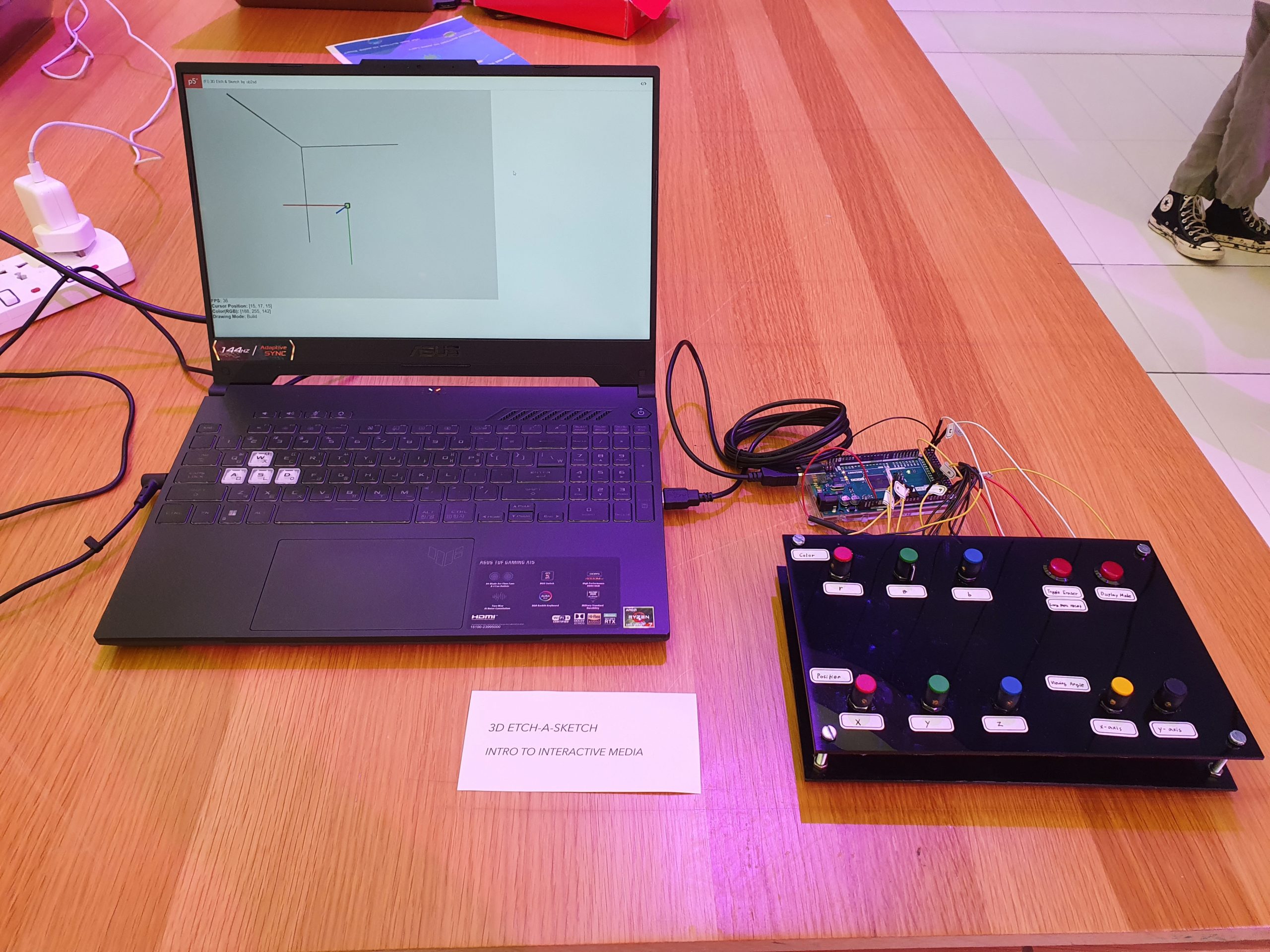
As a result, my final product looks like the below image. A black control panel with 8 knobs and 2 buttons. Laptop screen is used to display the drawings.
Arduino Code
The Arduino code reads values from sensors, stores converted or raw values into different variables, convert, and send values to p5.js. It also receives whether p5.js finished a reset process. The detail is as the following:
-
-
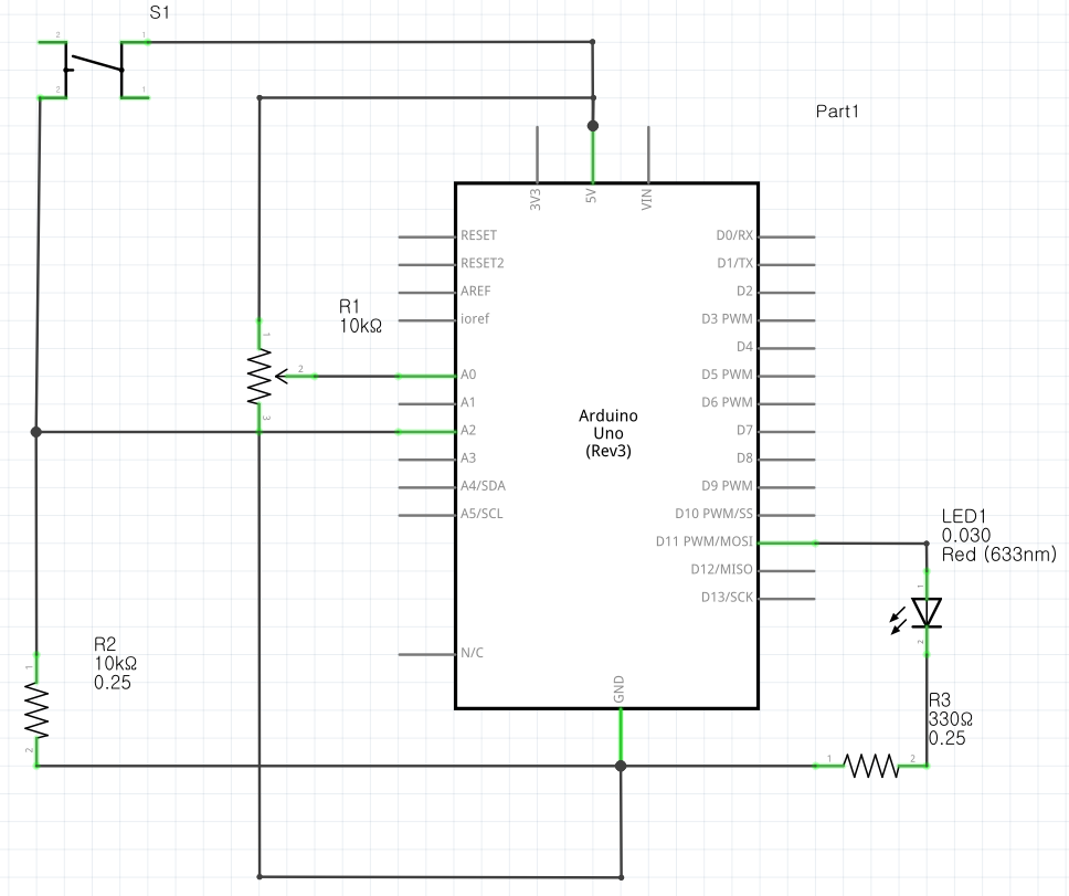
- Sensors: 8 potentiometers and 2 switches (buttons)
- 3 potentiometers: x, y, z coordinate of the drawing block (0-30)
- 3 potentiometers: R, G, B value of the drawing block (0-255)
- 2 potentiometers: x, y angle of rotation of entire drawing (0-360)
- 1 switch: choose among displayAll/disableIndicators/disableAll
- displayAll: display 3D space indicators and block outline
- disableIndicators: disable 3D space indicators
- disableAll: disable 3D space indicators and block outline
- 1 switch: toggle eraser mode & long press to reset all
- Build: normal drawing block
- Remove: invisible drawing block (erase blocks)
- Reset Warning: press 1.2 seconds to enter, warn that if pressing is continued, entire drawing will be removed
- Reset: continued press (total 2.4 seconds) to enter, clear all blocks
- Sensors: 8 potentiometers and 2 switches (buttons)
-
Arduino code is embedded in the p5.js sketch.
P5.js Code
The role of p5.js code is to display the drawing and other miscellaneous information.
-
-
- On setup, a 31 x 31 x 31 block space will be created
- Convert x, y, z values into 3D space coordinates
- Convert R, G, B values into a color of the drawing block
- Convert px, py values into a 3D perspective (view angle)
- displayAll/disableIndicators/disableAll
- displayAll: display 3D space indicators and block outline
- disableIndicators: disable 3D space indicators
- disableAll: disable 3D space indicators and block outline
- toggle eraser mode & reset warning/reset all
- Build: normal drawing block
- Remove: invisible drawing block (erase blocks)
- Reset Warning: press 1.2 seconds to enter, warn that if pressing is continued, entire drawing will be removed
- Reset: continued press (total 2.4 seconds) to enter, clear all blocks
-
Here is the link to the p5.js code.
Communication between Arduino and p5.js
Arduino to p5.js:
-
-
- x, y, z coordinates of the drawing block (cursor)
- r, g, b color of the drawing block
- px, py (rotation axis of the viewing angle)
- eraserMode
- displayMode
-
p5.js to Arduino
-
-
- whether the sketch finished the reset process
-
Details are describes in above sections.
Highlights
p5.js:
show() {
  let fd = this.voxelSize * this.d; // used to go to next row
  let cd = fd / 2 + this.voxelSize / 2; // used to center voxel display
  translate(-cd, -cd, -cd);
  ...
  for (let i = 0; i < this.d; i++) {
    translate(this.voxelSize, 0, 0);
    for (let j = 0; j < this.d; j++) {
      translate(0, this.voxelSize, 0);
      for (let k = 0; k < this.d; k++) {
        translate(0, 0, this.voxelSize);
        this.voxels[i][j][k].show();
      }
      translate(0, 0, -fd);
    }
    translate(0, -fd, 0);
  }
  ...
}
This code displays each blocks (31 x 31 x 31) in the correct position. This code is nice because it is quite intuitive yet powerful.
Arduino:
void setEraserMode() {
  bool switchState = !digitalRead(btn_eraser);
  if (switchState) { // on
    unsigned long currentMillis = millis();
    if (!prevEraserSwitchState) { // when off > on
      eraserMillis = currentMillis;
    } else if (currentMillis - eraserMillis >= eraserTriggerDelay) { // 1.2 sec press: promptReset
      if (currentMillis - eraserMillis >= eraserTriggerDelay*2) {  // 2.4 sec press: resetAll
        eraserMode = 3;
      } else {
        eraserMode = 2;
      }
    }
  } else { // off
    if (prevEraserSwitchState) { // when on > off
      eraserMode = !eraserMode; // 0 becomes 1, nonzero becomes 0
    }
  }
  prevEraserSwitchState = switchState;
}
This code lets a switch(button) to serve multiple functions. You can press to toggle between two values (0 and 1) and, when pressed long, this code goes through different stages (3 and 4). If released in any time during higher stages, the value resets. This code is used in setting the eraserMode/reset.
Physical component:
The panel and casing seems to be made nicely. It is clean and sturdy.
Future Improvements
During the showcase, I realized that there could be a few improvements in my project:
-
-
- Visible indication of color changes. People tend to turn knobs slowly (partly due to it being a bit stiff), and it is often that people do not realize the color changes on the screen. They move on to other visibly interactive sensors.
- Removal of reset warning. Because reset warning shows a drastic change in view (a clear screen with warning message), people do not see it as a warning sign but instead an indication of actual reset. Also, people tend to not press the button for long period (1~ sec), so it may be better to have 2~2.5 sec delay with no reset warning.
- Improved stabilization of analog read. Although there were multiple measures of making analog read stable (delay, double check, average, heat shrink tubing, etc.), there were noises in reading and it was difficult to make the drawing precise.
-
 Overview
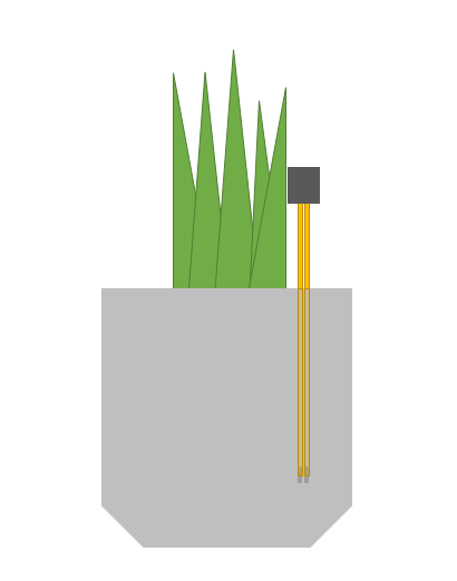
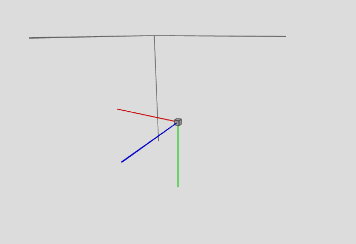
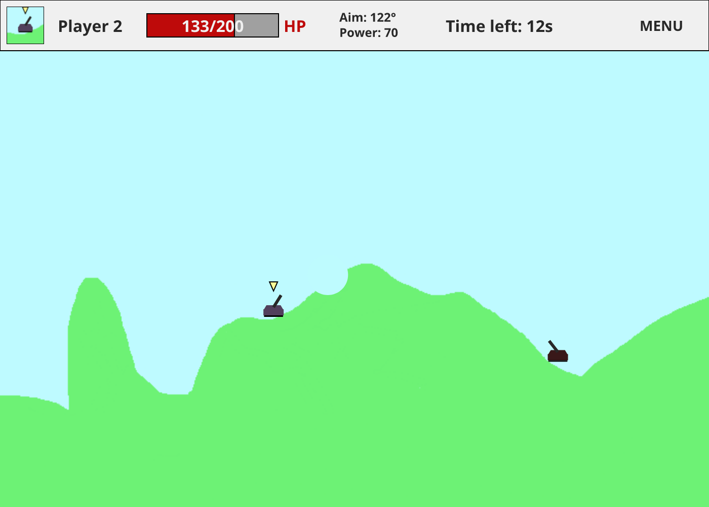 In-game display
 Click to view the full image – you can zoom in to see the details
 Click to view the full image – you can zoom in to see the details