Final Project

Concept

As I was describing in my previous blog posts, I have created a device that allows users to learn Braille’s alphabet and numbers from 0 to 9. Additionally, I have created a functional P5 sketch that shows instructions and the letter patterns on the screen, so users would be able not only remember the pattern physically but also visually.
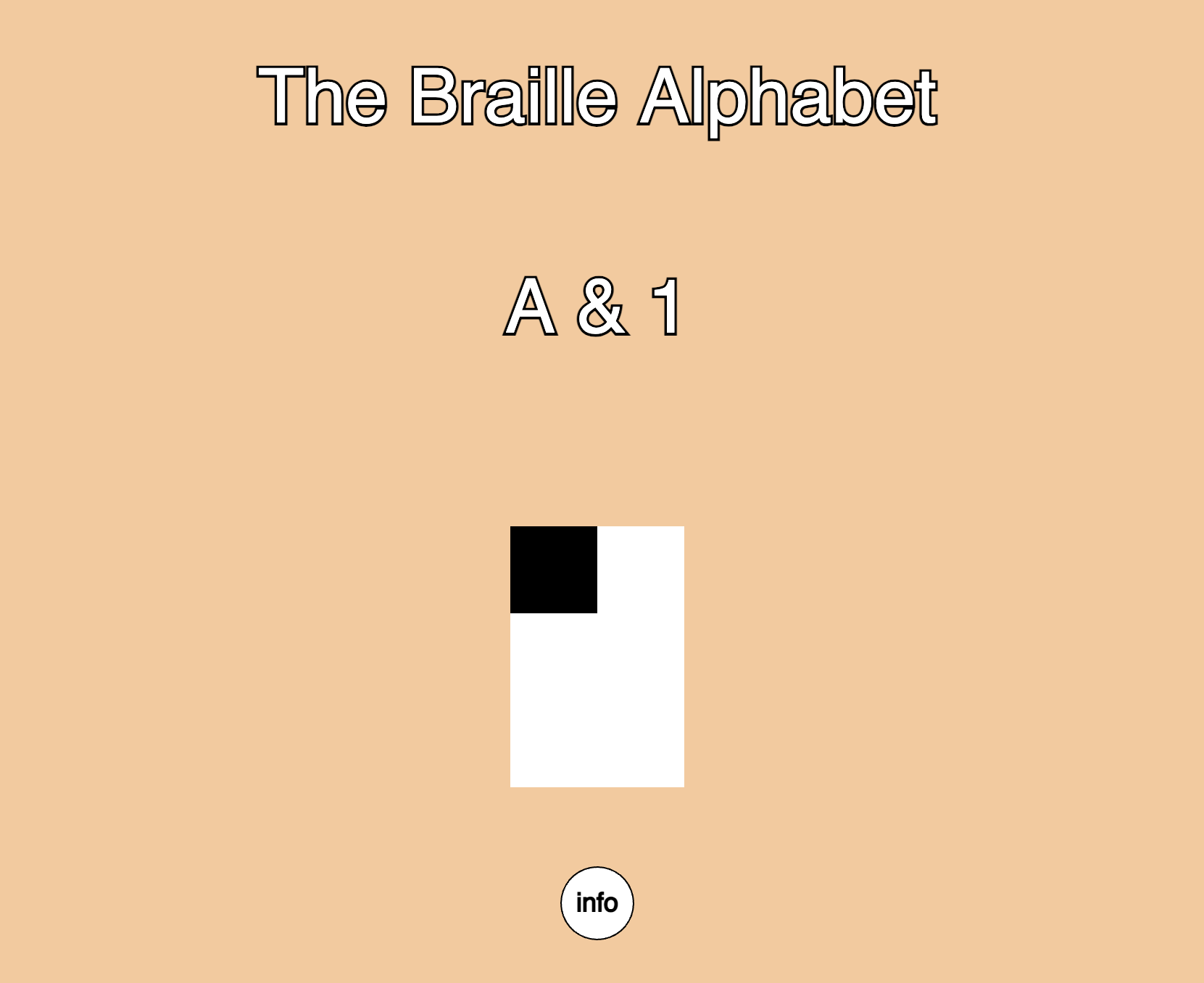
P5 sketch:

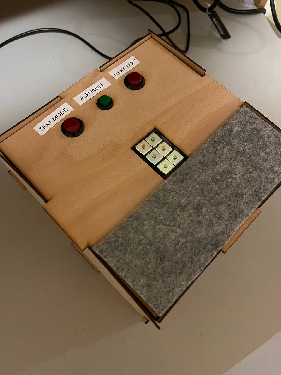
The upper view of the device:

How does it work?

The first thing that the user sees is the screen where the info button can be found. After clicking the button, P5 shows the instruction menu, which tells the user how to use the device.

When the user clicks the green button, the program starts working: the solenoids start moving, pushing the pins according to the letter’s pattern. Letters go in alphabetical order from A to Z. While the button is down, the Arduino pushes the solenoids, and P5 shows the letter’s pattern on the screen together with the letter itself to enhance the user experience.

In my original idea, I wanted to implement the opportunity for the users to read the texts using the Braille alphabet, but for demonstration purposes, I decided to wait with its implementation. The logic behind interpreting the text is the same as with the alphabet.

VIDEO_DEMONSTRATION

Arduino & P5 code

#define A 1
#define B 2
#define C 3
#define D 4
#define E 5
#define F 6
#define G 7
#define H 8
#define I 9
#define J 10
#define K 11
#define L 12
#define M 13
#define N 14
#define O 15
#define P 16
#define Q 17
#define R 18
#define S 19
#define T 20
#define U 21
#define V 22
#define W 23
#define X 24
#define Y 25
#define Z 26

const int solenoide_1 = 5;
const int solenoide_2 = 3;
const int solenoide_3 = 6;
const int solenoide_4 = 9;
const int solenoide_5 = 10;
const int solenoide_6 = 11;

const int buttonTextMode = 13;
const int buttonAlphabet = 12;
const int buttonNextText = 4;

int alphabet[] = { A, B, C, D, E, F, G, H, I, J, K, L, M, N, O, P, Q, R, S, T, U, V, W, X, Y, Z };

int alphabetMode = 0;  // 0 for inactive, 1 for active
int textMode = 0;

void setup() {
  Serial.begin(9600);
  pinMode(solenoide_1, OUTPUT);
  pinMode(solenoide_2, OUTPUT);
  pinMode(solenoide_3, OUTPUT);
  pinMode(solenoide_4, OUTPUT);
  pinMode(solenoide_5, OUTPUT);
  pinMode(solenoide_6, OUTPUT);
}

void loop() {

    digitalWrite(solenoide_1, LOW);
    digitalWrite(solenoide_2, LOW);
    digitalWrite(solenoide_3, LOW);
    digitalWrite(solenoide_4, LOW);
    digitalWrite(solenoide_5, LOW);
    digitalWrite(solenoide_6, LOW);
    
    int currentButtonAlphabetState = digitalRead(buttonAlphabet);

    if (currentButtonAlphabetState == 1 && alphabetMode == 0) {
      // Transition from inactive to active
      alphabetMode = 1;
    } else if (currentButtonAlphabetState == 0 && alphabetMode == 1) {
      // Transition from active to inactive
      alphabetMode = 0;
    }

    int TextMode = digitalRead(buttonTextMode);
    int NextText = digitalRead(buttonNextText);
    int thisLetter = 0;

    Serial.print(currentButtonAlphabetState);
    Serial.print(',');
    Serial.print(TextMode);
    Serial.print(',');
    Serial.print(NextText);
    Serial.print(',');
    Serial.println(thisLetter);
  

    while (thisLetter < 26 && alphabetMode == 1){
      currentButtonAlphabetState = digitalRead(buttonAlphabet);
      if (currentButtonAlphabetState == 1 && alphabetMode == 0) {
      // Transition from inactive to active
      alphabetMode = 1;
    } else if (currentButtonAlphabetState == 0 && alphabetMode == 1) {
      // Transition from active to inactive
      alphabetMode = 0;
    }
      Serial.print(currentButtonAlphabetState);
      Serial.print(',');
      Serial.print(TextMode);
      Serial.print(',');
      Serial.print(NextText);
      Serial.print(',');
      Serial.println(thisLetter);
      if (alphabet[thisLetter] == I || alphabet[thisLetter] == J || alphabet[thisLetter] == S || alphabet[thisLetter] == T || alphabet[thisLetter] == W){
        digitalWrite(solenoide_1, LOW);
      } else {
        digitalWrite(solenoide_1, HIGH);
      }
      if (alphabet[thisLetter] == A || alphabet[thisLetter] == B || alphabet[thisLetter] == E || alphabet[thisLetter] == H || alphabet[thisLetter] == K || alphabet[thisLetter] == L || alphabet[thisLetter] == O || alphabet[thisLetter] == R || alphabet[thisLetter] == U || alphabet[thisLetter] == V || alphabet[thisLetter] == Z){
        digitalWrite(solenoide_2, LOW);
      } else {
        digitalWrite(solenoide_2, HIGH);
      }
      if (alphabet[thisLetter] == A || alphabet[thisLetter] == C || alphabet[thisLetter] == D || alphabet[thisLetter] == E || alphabet[thisLetter] == K || alphabet[thisLetter] == M || alphabet[thisLetter] == N || alphabet[thisLetter] == O || alphabet[thisLetter] == U || alphabet[thisLetter] == X || alphabet[thisLetter] == Y || alphabet[thisLetter] == Z){
        digitalWrite(solenoide_3, LOW);
      } else {
        digitalWrite(solenoide_3, HIGH);
      }
      if (alphabet[thisLetter] == A || alphabet[thisLetter] == B || alphabet[thisLetter] == C || alphabet[thisLetter] == F || alphabet[thisLetter] == I || alphabet[thisLetter] == K || alphabet[thisLetter] == L || alphabet[thisLetter] == M || alphabet[thisLetter] == P || alphabet[thisLetter] == S || alphabet[thisLetter] == U || alphabet[thisLetter] == V || alphabet[thisLetter] == X){
        digitalWrite(solenoide_4, LOW);
      } else {
        digitalWrite(solenoide_4, HIGH);
      }
      if (alphabet[thisLetter] == A || alphabet[thisLetter] == B || alphabet[thisLetter] == C || alphabet[thisLetter] == D || alphabet[thisLetter] == E || alphabet[thisLetter] == F || alphabet[thisLetter] == G || alphabet[thisLetter] == H || alphabet[thisLetter] == I || alphabet[thisLetter] == J || alphabet[thisLetter] == W){
        digitalWrite(solenoide_5, LOW);
      } else {
        digitalWrite(solenoide_5, HIGH);
      }
      if (alphabet[thisLetter] == U || alphabet[thisLetter] == V || alphabet[thisLetter] == W || alphabet[thisLetter] == X || alphabet[thisLetter] == Y || alphabet[thisLetter] == Z ){
        digitalWrite(solenoide_6, HIGH);
      } else {
        digitalWrite(solenoide_6, LOW);
      }
      delay(2000);
      digitalWrite(solenoide_1, LOW);
      digitalWrite(solenoide_2, LOW);
      digitalWrite(solenoide_3, LOW);
      digitalWrite(solenoide_4, LOW);
      digitalWrite(solenoide_5, LOW);
      digitalWrite(solenoide_6, LOW);
      delay(1000);

      thisLetter++;

    }
}

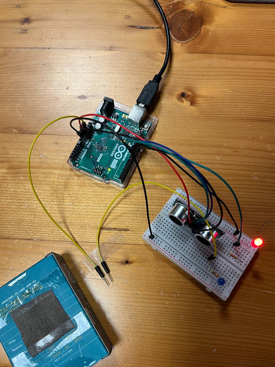
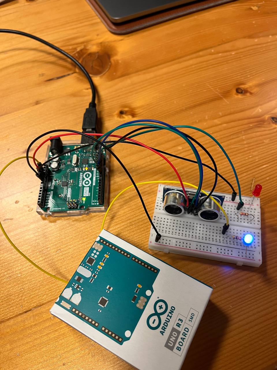
The following video shows the Arduino circuit

CIRCUIT_VIDEO

P5 sketch:

Communication

In my project, I only needed one-way communication: from Arduino to P5. Arduino is continuously sending P5 the values of three buttons and the value of the thisLetter variable. This variable tells P5 what pattern and what letter it has to show while the green button is pressed.

Aspects of the project I’m proud of

First and foremost, I’m proud of implementing my original idea and making it, even though it turned out not as I imagined it at the initial stage. This project taught me how to use solenoids and how to solder. I’m proud of my persistence and that I went all the way and solved every problem along the way.

Areas for future improvement

The first thing that comes to mind, and it’s exactly what I thought about at the initial stage of the project. It is to reduce the size of the device, so it would fit the size of an index finger without the need for the whole box. But for this, I will have to use something else, not Arduino. After the demonstration, I will add the text mode, and I would like to give a user an opportunity to download the files in the folder from which Arduino would be able to read the texts and then, using the solenoids, translate them into Braille.

User testing

The idea of adding the instructions appeared while I was asking my friends to test my device. All of them firstly tried to push the solenoids inside the box like buttons, and I had to explain them that they are working differently. Then, I added the functions’ descriptions of the buttons either in P5 and on the device, which at the end of the day gave a better idea to the user of what to do, and what to expect from the program.

Another problem was that people aren’t really familiar with how to read Braille. Do you have to use the palm? Or maybe two fingers? Or one is enough? But if you show the user the best position for the hand, they admit that the device fully fulfills its purpose. Maybe I should have added the picture of the hand on the device, but the most comfortable position stills varies from person to person; therefore, I decided to give a user more freedom with finding the best position.

In user testing the device was working well, except for the times when people put too much weight on the solenoids. The 5V solenoids aren’t that strong, and they can’t push the weight of the human hand. I had to explain the users that in order to use the device properly they need to shift the center of gravity.

Sources

https://youtu.be/RfrDtAEQ95c?feature=shared

Week 12 – Final Project Description

FINALIZED CONCEPT

I decided to stick with the idea of creating a Braille reader. The design of the device will be close to this, but I’m thinking about adding an additional hole for the light sensor, which will detect if the finger is placed on the device.

The platform will be the size of an index finger, allowing the user to use the device in limited spaces.

The solenoids will be used to put the parts into motion and will be controlled by the Arduino program, which will control their state. As my device is designed for people with sight problems, I will use the P5 only for the audio functions, allowing a person to get familiar with the functionality of the device on their own.

I will provide the user with two modes, controlled by the switches: reading mode and alphabet mode. Moreover, there will be one additional switch allowing the user to stop the program completely. In the reading mode, the device will work according to the texts downloaded into P5, while the alphabet mode will teach a person the alphabet while providing a sound accompaniment to the program.

The P5 sketch will receive information about the state of the switches, and if the Alphabet mode is activated, it will start receiving information from the Arduino about the state of the solenoids and, according to that, sounding out the corresponding letters.

Week 11 – Reading Reflection

According to the World Health Organization, 1.3 billion people, or 16% of the population, have significant disabilities. With the invention of new technology, most of the disabilities can be treated, providing a person with a relatively normal lifestyle. However, there’s a stigma posed by society that makes it treat people with disabilities differently, which complicates the process of socialization for them. And design, along with fashion, can be a great force in transitioning people’s beliefs towards accepting and equalizing our society. While I was reading, I was curious to find out how glasses, being an attribute of people with sight problems, have become an essential object of fashion in recent decades.

I believe that there should be more investments in the field of biological and medical advances that would enable the group of people with disabilities to enjoy life and implement their intellectual abilities. Design should become the transitional power to understand and accept people with disabilities, but there’s still a long way to go until people with disabilities are treated equally in most of the world.

Final Project Ideas

Idea 1

I would like to combine my midterm project with the final project, creating a tool that allows a person to learn to play the piano with a midi keyboard. My sketch on P5 will offer a user a variety of songs and an opportunity to add unique ones. The key that needs to be pressed will be shown on the screen, and if the right key is pressed, Sketch will show the next key.

Idea 2

During the last reading, I came up with the idea of creating a device that would allow blind and deaf, or blind people to read Braille. It would look like a small platform for a finger, which will have six points. The device will elevate the points according to the letters they represent in Braille. The user will be able to control the speed of the reading and upload their own text.

Week 11 Exercises

Exercise 1

function draw() {
  background(250, 200, 152);

  if (!serialActive) {
    print("Press Space Bar to select Serial Port", 20, 30);
  } else {
    print("Connected");

    // ellipse
    noStroke();
    fill(255, 0, 0);
    ellipse(map(rVal, 0, 1023, 0, width), height / 2, 100, 50);
  }
}

Link to the sketch: Sketch Exercise 1 

Exercise 2

function draw() {
  background(250, 200, 152);

  if (!serialActive) {
    print("Press Space Bar to select Serial Port");
  } else {
    print("Connected");
    
    brightness = Math.floor(map(rVal, 0, 1023, 0,255));
    right = Math.floor(brightness);
  }
}

The only change in Arduino code I made was using analogWrite instead of digitalWrite.

Link to the sketch: Sketch Exercise 2

Exercise 3

function draw() {
  
  background(250,200,152);
  
  if (!serialActive) {
    print("Press Space Bar to select Serial Port");
  } else {
    if (state == 1){
    
    applyForce(wind);
    applyForce(gravity);
    velocity.add(acceleration);
    velocity.mult(drag);
    position.add(velocity);
    acceleration.mult(0);
    ellipse(position.x,position.y,mass,mass);

    if (position.y > height-mass/2) {
      velocity.y *= -0.9;  // A little dampening when hitting the bottom
      position.y = height - mass/2;
    } 

    if (position.y >= height - mass/2 - 5) {
      left = 1;
    } else {
      left = 0;
    }

  wind.x = map(rVal, 0, 1023, -1, 1)
    }
  }
}

For this sketch, I used the state machine to allow the Arduino to load before the ball starts to fall. Otherwise, the LEDs wouldn’t work properly.

Link to the sketch: Sketch Exercise 3

Video demonstration: VIDEO

Assignment 10 – IM (Ivan & Muhammad) Techno

Concept

It took a while for us to come up with a properly functioning musical instrument with a decent sound. At first, we tried to incorporate an ultrasonic sensor for controlling the height of a sound, a servo motor to create a beat, and a flex sensor for controlling the duration of the notes. It turned out to be fine, but we weren’t satisfied with the quality of the sound or its instability. After a little experimenting, we finally decided to use transistors to amplify the sound, which gave the music a feel of the techno genre.

Technical structure

We decided to use a transistor to amplify the signal to the speaker. Moreover, we added an external 9V power supply to power the speaker, and these additions greatly enhanced the volume and clarity of the sound. The potentiometer controlling the volume is connected in series with the input signal to the speaker from the Arduino, and so the physical reduction of the voltage of the signal by adjusting the resistance of the potentiometer controls the volume. Therefore, we use the potentiometer as a variable resistor instead of an input here.

On the other hand, the potentiometer used for the delay is used to get analog input to the Arduino, which is then used to control the delay interval in code. This is just a way to showcase the different use cases of the same components.


Video demonstration:


Code

int mapDistanceToIndex(float distance) {
  // Map distances into array index (2 cm steps from 5 cm to 15 cm)
  // int index = constrain((distance - MIN_DIST) / 2, 0, ARRAY_LENGTH - 1);
  int dist = int(distance);
  int index = constrain(map(dist, MIN_DIST, MAX_DIST, 0, ARRAY_LENGTH - 1), 0, ARRAY_LENGTH - 1);
  return index;
}

void loop() {
  float dist = getDistance();

  noteDuration = map(analogRead(OFFSET_DIMMER), 0, 1023, 100, 500);

  if (millis() - noteStartTime >= noteDuration) {
    // noTone(SPEAKER_PIN);
    // delay(10);
    // Play a funky note continuously based on the distance range
    if (dist >= MIN_DIST && dist <= MAX_DIST) {
      int note = FUNKY_NOTES[mapDistanceToIndex(dist)];


      Serial.print(dist);
      Serial.print("cm ");
      Serial.print(note);
      Serial.print("HZ");
      Serial.print(" with duration = ");
      Serial.print(noteDuration);
      Serial.println();

      // Check if the note duration has elapsed, then check for a new note


      // If the note has changed, start a new note
      if (note != lastNote) {
        lastNote = note;
        tone(SPEAKER_PIN, note);
        noteStartTime = millis();  // Record the start time of the current note
      }
    } else {
      noTone(SPEAKER_PIN);
    }
  }

Reflection

We have succeeded in creating a new instrument that wouldn’t just become the replication of already existing ones. Furthermore, we had a chance to experiment with new sensors and get experience working with transistors and potentiometers, implementing them in one project. We believe there’s more potential for this project, especially if we could use the mp3 files. Nevertheless, we had fun working on this project, experimenting with Arduino.

Week 10 – Reading Reflection

When I was young, I used to watch fiction movies portraying the future. I’ve seen that the vision of it shifts significantly over time because, whereas filmmakers strive to develop pre-existing technologies, inventors revolutionize them by bringing in new ideas and perspectives on the world. For instance, I recall the old movie where the main characters could instantly get any book, which would appear in a special box if they said its title. Right now, with the invention of the Internet and smartphones, we can get the same result, but the way we do it is remarkably different. In that sense, I absolutely support the position of Bret Victor about stopping to visualize our future as an advanced version of the present, but rather thinking about how we might revolutionize it and create something entirely new.

Regarding the use of “Picture Under Glass”, I believe it will still be used for at least 3 decades, but personally, I would like to see the transition to the new form of control. Bret Victor promotes the idea that, similar to how we use physical objects and tools, we should use technology in a naturally human way. More or less, I support the idea of involving human actions as a way of controlling things, but I don’t think that it’s the only way to go, as it’s hard to see the world where every control will involve action or physical sensation. It may be implemented alongside other technologies, but not as the only path to technological development.

Week 9 – Reading Reflection

Making Interactive Art: Set the Stage, Then Shut Up and Listen

While reading the article, I resonated a lot with the author. I do believe that artists should create a space where the mind of a person experiencing the artwork can feel free to explore. By doing so, the artist can not only analyze how interactive and understandable the artwork is, but also take a look at their own work from different perspectives.

The other great point was about not making people adopt the author’s interpretation of the work. I do believe that every artwork should find its own unique place in a person’s mind. And that’s why the idea of artwork having only one interpretation doesn’t make any sense to me.

On the other hand, I do believe that for complex projects, guidance for the user is necessary, even though it can be interpreted as “giving a user a way of doing things”. But otherwise, the initial idea of creating a free space doesn’t see the light because the user may not be able to enter that space.

Physical Computing’s Greatest Hits (and misses)

I really enjoyed the idea described in the first paragraph that it’s worth doing something that has already been done because there’s always room for originality. But I also believe that humans should be inventors, and before pursuing any type of work, think if there’s something more that can be done.

The article gave me ideas that can be used in the projects. I saw most of the ideas mentioned in the article being implemented in real life. Particularly, I see a lot of room for originality in the project involving gloves.

Assignment 9 – “Don’t steal my Arduino UNO Part 2”

Concept

For this assignment, I decided to advance my first assignment by using an analog sensor (ultrasonic range finder) to calculate the distance to the object, indicating if it has been moved too far from the sensor.

Technical structure

For the digital switch, I used the one from the last assignment, where the conductive fabric was used to complete the circuit when an object touched the wires. When it happens, the blue LED lights up.

  .  

As I mentioned earlier, for the analog switch, I decided to use the ultrasonic range finder. It turned out that working with this sensor is quite easy; however, while I was testing the sensor, I found that sometimes the waves go through the object (e.g., hands), and the sensor detects dramatic changes in distance, which makes it slightly inaccurate.

The program is constantly checking the distance to the object, and when the distance detected is more than 10 cm, the red LED starts fading.

Code

void loop() {

  digitalWrite(trigPin, LOW);
    delayMicroseconds(2);

    digitalWrite(trigPin, HIGH);  
    delayMicroseconds(10);  

    digitalWrite(trigPin, LOW); 
  duration = pulseIn(echoPin, HIGH);
  distance = (duration*.0343)/2;

  if (distance >= 10){
    analogWrite(led, brightness); // set the brightness of pin 11:
    brightness = brightness + fadeAmount; // change the brightness for next time through the loop:

    // reverse the direction of the fading at the ends of the fade:
    if (brightness <= 0 || brightness >= 255) { 
      fadeAmount = -fadeAmount;
    }

    // wait for 3 milliseconds to see the dimming effect
    delay(3);
  } else {
    analogWrite(led, 0); // turn off the light if the object is within 10 cm distance
  }

  Serial.print("Distance: ");  
    Serial.println(distance);  

    delay(10);
}

In this part of the code, the loop function for the project is described. The first part controls the functionality of the switch, and starting with the if function, the red LED is being controlled. In line 11, the duration is multiplied by 0.343 because the speed of sound in centimeters per microsecond is .0343 c/μS. Then it’s being divided by two because the sound waves travel to the object and back.

Demonstration

Link to the video: Assignment demonstration

Reflection

While working on the assignment, I realized that making a theft detection device is not as simple as it seems to be. The device I created can be easily bypassed by placing another object in front of the sensor. But if the person is not aware of how the system functions, the device can be used successfully. I enjoyed working with a new sensor, and I hope to expand my knowledge of Arduino more.

Sources used:

“Getting Started with the HC-SR04 Ultrasonic sensor”

https://projecthub.arduino.cc/Isaac100/getting-started-with-the-hc-sr04-ultrasonic-sensor-7cabe1

Assignment 8 – “Don’t steal my Arduino UNO”

Concept

For this assignment, I tried to come up with a functional switch that could be potentially used in real life. As it was my first time working with electronics, I found it very interesting to explore different tools and materials that could be used in the project.

After some consideration, I decided to create a theft detection switch that is triggered when an object is taken out of the place. One of the complications I had to solve was to make a switch more convenient by not connecting the wire directly to the object that was being tracked.

Technical structure

For this switch, I used conductive fabric, which was put on the back of the object. I secured two wires on the table, one of which was connected to an Arduino Uno, while another was connected to a solderless breadboard. When an object is lying on the wires, the circuit completes and the LED lights up. The moment you take the object from its place, the LED goes out.

Demonstration

Link to the video: Switch_demostration

Reflection

I really enjoyed working with electronics, and I see how many things can be done using them. I’m glad I managed to find a practically usable switch that could be potentially used in future work. I’m looking forward to learning more about Arduino and creating more and more sophisticated projects.