Final – Arduino of Time

Where has the time gone? The semester is nearly over, and Christmas so close. The incomprehensible specter of 2023 peeks around the corner, and I again lament the graying of memories. Yet there is a gift that has been granted unto humanity that can color in even the most ashen of memories: music. For they say that music is the vessel of memory, and memory the muse of music.

Concept & Description

The original concept—an Arduino-powered musical instrument that users can physically interact with to play songs that activate certain effects in p5js—has fortunately withstood the tides of reality! I was also able to write up an overarching mini-narrative of sorts that serves as a framing device that ties the project together and allows for the user to have a more immersive experience.

Explained at the beginning of the p5js sketch before the main game, the premise of the project is that the user plays as an amnesiac who recovers pieces of their memory through 6 songs that are tied to certain memories and emotions of the past. The user is then presented with a list of six songs, with each one having a combination of buttons/notes—playing a song correctly on the Arduino instrument triggers an according scene of remembrance, which is represented by a short video of said memory being played together with a text box.

The project is heavily inspired by the Legend of Zelda video game series, owing to it not just the initial inspiration but also much of the assets. All 6 songs are actual songs from Legend of Zelda: Ocarina of Time, and the aesthetic direction + images and videos are from Legend of Zelda: Breath of the Wild.


Implementation & Highlights

Building upon the progress made in the last post—in which I assembled and coded the Arduino instrument, with the value corresponding to the pressed button/played note being sent to p5js—the next main step was to work on writing code in p5js that 1) gathers and holds on to the data from Arduino and 2) checks if the combination of said incoming data corresponds to one of the six songs 3) plays a number of effects corresponding to the song that has been played (if there is any). The following block of code is the method I used to achieve the first part of this step:

//Method for Collecting Arduino Data//

//Make Array to Gather Notes
const notesArray = [];

function readSerial(data) {
  ////////////////////////////////////
  /////  READ FROM ARDUINO HERE  /////
  ////////////////////////////////////
// Make sure there is actually a message
  if (data != null) {
    let fromArduino = data;
//Reset Array If It's Full (6 Notes)
    if (notesNum >= 6){
      for (i = 0; i < notesNum; i++){
        notesArray.pop();
      }
    }
//Add Played Note to the Array
    notesArray.push(data);
  }
}

As each song is an arrangement of six notes, the array needs to be able to hold onto the notes until it reaches a total of six. If a note is played after the sixth has been recorded, the array is reset to make way for a new combination. When an array is full, the second part of the step is carried out through the following code:

//Song is Stated as Array
const stormsSong = [0, 1, 4, 0, 1, 4];

//Function Used to Compare User Input to Songs
function songCheck(s1, s2){
  return s1.toString() == s2.toString();
}

//The Code Below is in Draw()
//Example: If Song is Played, Effects Activate
if ((songCheck(notesArray, timeSong)) == true){
 if (songPlaying() == false){
 //Audio File Played
  timeAudio.play();
 //Trigger Variable Set to True
  timeTrigger = true;
 }
}
//True Trigger Variable Activates Function Containing Effects
if (timeTrigger == true){
 timeMemory();
}

The function songCheck() uses the .toString() method to convert two chosen arrays into two string objects, which it then uses to compare and return whether the two are the same. As demonstrated in the example, an if() loop containing this function is used to compare notesArray with one of the six preexisting songs, which are also arrays (in this case, timeSong, an array for the Song of Time)—and if the song played on the Arduino instrument matches the song, a set of effects corresponding to the song are played.

A little explanation on the “effects”: playing each tune triggers an audio file from Ocarina of Time of the in-game ocarina playing said tune (this is prompted by the timeAudio.play() line of code), a video or gif of a scene from Breath of the Wild that corresponds with the song (which represents a memory), and a text box above it that contains a short, sentimentally written passage. Playing the Song of Time results in a trigger variable named timeTrigger being set to true, which in turn activates a function named timeMemory that contains the code for the video and text:

//Function Containing Video and Text for Song of Time
function timeMemory(){
//Video is Mapped to Image and Played
  let timeImg = timeVid.get();
  image(timeImg, 0, 0, 960, 540);
  timeVid.play();
//Make Text Box
  tint(255, 150);
  image(memoryBG, 40, 308, 880, 182);
  noTint();
//Write Text; TypeWriter Effect
  fill(185, 159, 102);
  textSize(40);
  let currentString = timeString.substring(0, currentCharacter);
  push();
  text(currentString, pageMargin + 10, 313, width - pageMargin*2, height - pageMargin);
  pop();
  currentCharacter += random(0.3, 0.5);
}

Thus is the general pattern for all 6 of the songs and the overall gameplay loop—each song has an array containing the notes; the tune last played by the user on the Arduino instrument is checked against each song; if there is a match, the effects bound to the song are played; after the song and video has played once, the screen returns back to the scene that shows the songlist; users can then play another song again and see its effects.


For the physical part of the project, I decided to make a nifty box of a controller-instrument with buttons and a speaker that are connected to the Arduino housed within. With help from the Lab Assistants, I was fortunate enough to be able to use the laser cutter in the IM Lab to acquire six wooden panels (the top panel having five circular holes for the buttons and one rectangular hole for the speaker, and the side panel on the right having a little hole through which the USB cable runs) that I taped together to make a rectangular prism.

One major step that I was worried about was soldering wires onto the big buttons that I chose to use (they’re so much more satisfying to press than the little ones that come in the kit). Despite having watched Professor Shiloh give a clear demonstration in class, I was nervous about trying my own hand at it. After watching a few tutorials as a refresher, I booted on the soldering station and clenched the iron in my hand—and to my surprise, it came rather easily! By the time I was soldering the wires onto the fifth and last button, I felt that I had gotten the hang of it and was somewhat successful at making the drops look nice and neat.

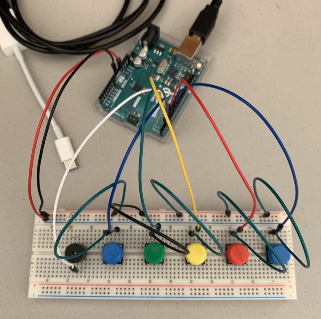
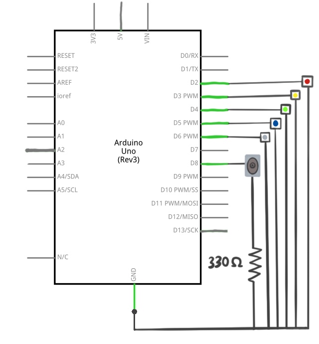
With the buttons all wired up and the wooden box complete, I was ready to assemble my controller-instrument. The original circuit looked like this:
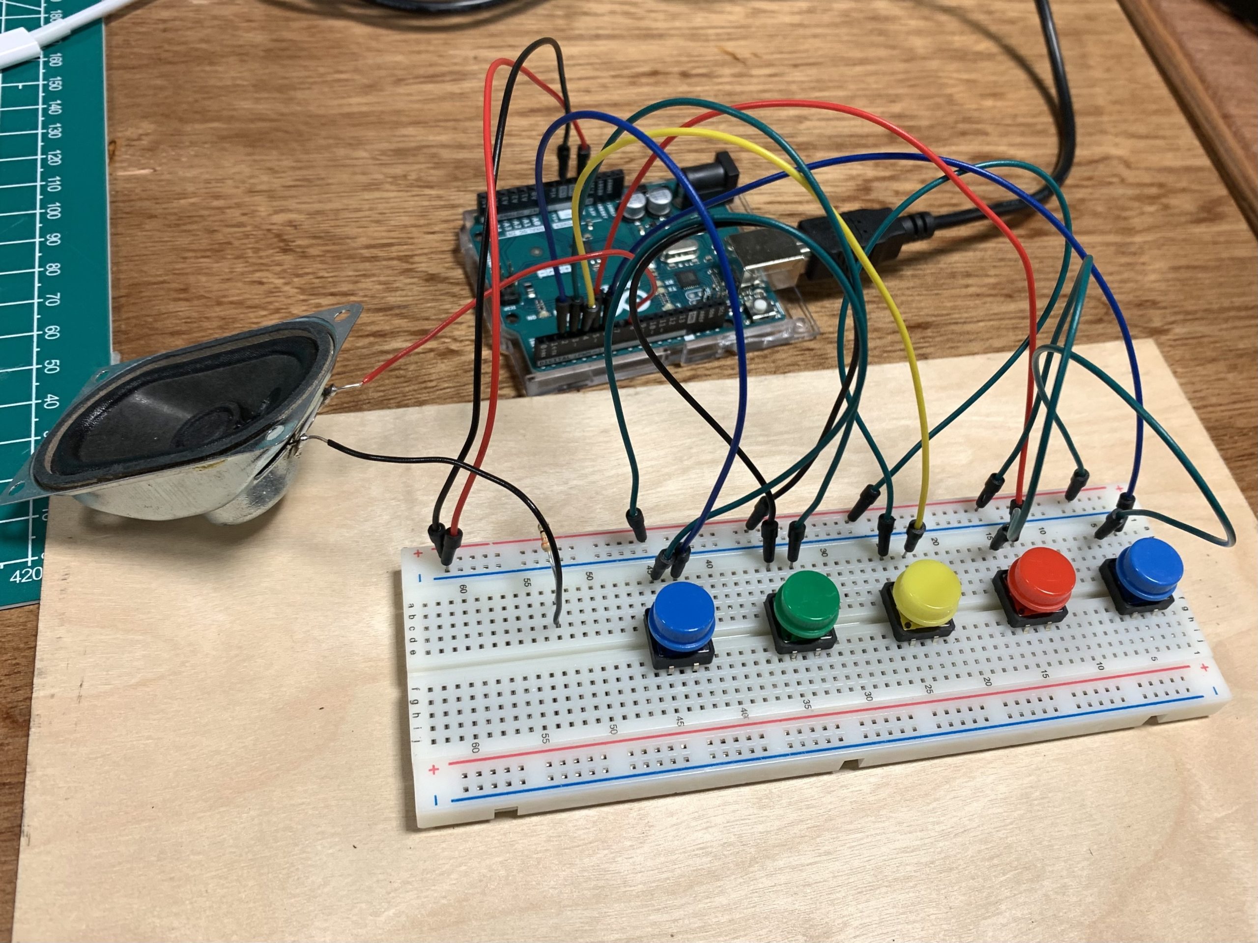
Placing the Arduino and breadboard inside the box, I carefully deconstructed the parts of the circuit that needed to be adjusted and hooked the buttons to the breadboard one by one…and voila!
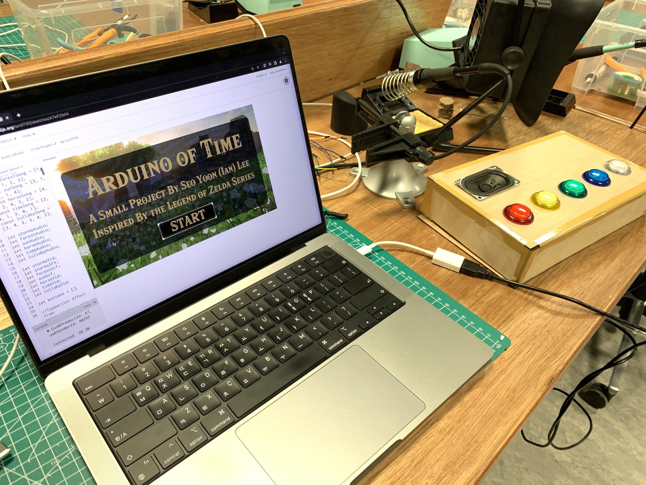
The fabled Arduino of Time.


Video Demonstration


Reflections

It’s been an amazing journey, and I’m very proud 0f what I was able to achieve for this final project! I’ve said it time and time again on this blog, but it really is a wondrous experience to fish an idea out of your mind, build upon it, and create something palpable. This course has not only taught me the basics of p5js and Arduino, but also inducted me into the realm of IM thinking—a space that encourages one to act upon creative ideas and engage with them in meaningful ways. And so the semester comes to a close…but I will continue to hold on to what I have learned.

Final – User Testing

User Testing

Shown below is a video of one of my suitemates testing out my project! It was great to be able to show off my project to someone who knows that I’ve been working (and struggling, haha) on this for a while but has never actually seen it in action.

He tested it out without much prior knowledge or instructions and was able to figure out almost immediately how things worked! It was encouraging to feel that my project does have at least some intuitive design. He also found it nice that the user’s interactions with the Arduino instrument and the pj5s sketch were linked in a musical way—this too was very encouraging, as I personally liked my own idea of using music as a means of engagement. All in all, this was some valuable input to receive!

Final – Update

I have admittedly fallen behind in terms of progress (in comparison to the current date), but I fortunately do have some updates to share! I have been able to commit to my chosen concept and start working on the primary components of the project.

The Concept, Revisited and Given Life

The base concept for my project involves an Arduino-based musical instrument of sorts that 1) the user can interact with to play notes and 2) is able to trigger a certain change in the p5js sketch when a correct tune—so a correct combination of notes—is played. As the general idea and its essential components were set in stone, I set out to first make the instrument itself. The plan was to have a device with five buttons that each play a different note through a speaker when pressed (D4, F4, A4, B4, D5). After some tinkering, I settled on a circuit that worked, the diagram of which looks like:

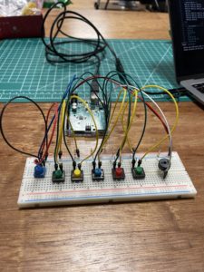
The actual circuit:

And now, the most prominent milestone so far: I was able to construct the code that I needed to achieve the desired effect from Arduino! Using arrays, I was able to simplify much of the repetitive code and condition checks, with the final result being:

#include "pitches.h"

int buttonPins[] = {
  2, 3, 4, 5, 6
};
int pinCount = 5;
int buttonStates[5];
int notes[] = {
  NOTE_D4, NOTE_F4, NOTE_A4, NOTE_B4, NOTE_D5
};
const int BUZZER_PIN = 8;
bool counter = false;

void setup() {
  Serial.begin(9600); // Initialize Serial
  for (int buttonPin = 0; buttonPin < pinCount; buttonPin++){
    pinMode(buttonPins[buttonPin], INPUT_PULLUP);
  }

  pinMode(BUZZER_PIN, OUTPUT); // Set Arduino Pin to Output Mode
  pinMode(13, OUTPUT);
}

void loop() {
  for (int buttonPin = 0; buttonPin < pinCount; buttonPin++){
    buttonStates[buttonPin] = digitalRead(buttonPins[buttonPin]);
  }
  for (int buttonPin = 0; buttonPin < pinCount; buttonPin++){
    if (buttonStates[buttonPin] == LOW) {
      if (counter == false) {
      Serial.println(buttonPin); //Sends Number of Button Being Pressed to p5js
      counter = true;
    }
    digitalWrite(13, HIGH);
    tone(BUZZER_PIN, notes[buttonPin], 500);
    delay(500);
    noTone(BUZZER_PIN); // Stop the tone playing:
  }
  else if (buttonStates[0] == HIGH) {
    digitalWrite(BUZZER_PIN, LOW);  // Turn off
    counter = false;
  }
  }
}

The use of for() loops in tandem with the buttonPins[] and notes[] arrays facilitates much of the input and output management here, with a notable line of code being Serial.println(buttonPin), which is used to send the “number” of the button being pressed to p5js. As I continue working on my project, I will be able to gather these outputs and run condition checks on p5js that determine whether the “correct” string of buttons (notes) has been played. Again, this will then trigger certain effects depending on the song. With the base Arduino-instrument completed, I can now move onto the next stages of the project—I look forward to what I can make of this vision!

Final – Proposal

To imagine that we are already at our final project! It seems like only yesterday that I was figuring out the arc() function in p5.js—yet here we are, preparing for the finale. The task is to harness the powers of both p5.js and Arduino in tandem, and I’m looking forward to see if I can realize a certain vision I’ve had in mind for a while now . . .

The Inspiration & Idea

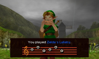
My inspiration is the ocarina mechanic in Legend of Zelda: Ocarina of Time. In the game, the main character Link possesses a magical ocarina that can have certain effects on the surrounding environment when certain melodies are played; for example, the Sun’s Song can change night to day and vice verse, while Zelda’s Lullaby is used to solve various puzzles (like opening doors with a certain insignia on them).

Since the very beginning of this course, I’ve had the vague vision of implementing this mechanic for my final project—and now that I’ve made it to this point, this vision is looking a little clearer. The plan is to use the musical capabilities of Arduino to build a makeshift instrument (in place of the ocarina), and p5.js to display a sort of environment that can be interacted with through Arduino. For instance, a treasure chest displayed in p5.js could be opened by playing the correct melody (the correct sequence of notes) on Arduino. The biggest feature and question mark here is the method I am going to use to 1) send information to p5.js containing the sequence of notes being played on the Arduino instrument; 2) check if the sequence of the notes being played is a viable melody; and 3) have the according element in the p5.js be impacted.

This will undoubtedly be my most challenging work yet, as I put together everything I have learned throughout this course to bring to life an interactive program that spans both the virtual and the physical. From making a working instrument to creating an interactive virtual environment, there is much to be done here. While I am equal parts excited and nervous about this project, I will only know of its true magnitude when I get into the thick of things. Off to work, then.

Assignment 8: Three Exercises

Exercise 1

This one was a simple matter of adding an ellipse() function (to the Arduino-p5.js connection example) in which the parameter for the x-coordinate is affected by the incoming serial data:

//In the draw function:
ellipse((inData/255 * 400), 200, 30, 30);

This line of code allows the horizontal location of the ellipse to be controlled by the potentiometer.

The link to the full code: https://editor.p5js.org/Ian0730/sketches/Nzxs9rlCa

Exercise 2

For this exercise, I modified Professor Sherwood’s example of bilateral connection so that the value of a variable defined in p5.js named brightness is sent to Arduino and used to control the brightness of an LED. This is the code in p5.js:

//p5.js Code
function draw() {
 ...
  // Click on place on canvas to adjust brightness
  if (mouseIsPressed) {
    brightness = round(map(mouseX, 0, 640, 0, 255));
    print(brightness);
  }
 ...
}
...
//Value of brightness is sent to Arduino
function readSerial(data) {
  if (data != null) {
    //SEND TO ARDUINO HERE
    let sendToArduino = brightness + "\n";
    writeSerial(sendToArduino);
  }
}

As seen in the code, the value of brightness is determined by the x-position of the mouse on the screen. It is then sent to Arduino, which runs the following code:

//Arduino Code
//Initialize Variables
int brightness;
int led1 = 5;
...
void loop() {
  // Wait for data from p5 before doing something
  if (Serial.available()) {
    brightness = Serial.parseInt();  //Arduino brightness = p5 brightness
    Serial.println(brightness);
    delay(30);
    analogWrite(led1, brightness); // Updates brightness of LED
  }
}

A variable also named brightness is constantly updated to match its counterpart in p5.js. It is then used as a parameter for determining the strength of the LED light in the line analogWrite(led1, brightness;. Thus, the LED light gets brighter the closer to the right side of the canvas the mouse cursor is pressed at (and vice versa).

The link to the full code: https://editor.p5js.org/Ian0730/sketches/_jqfjfe8V

Exercise 3

This was the most challenging exercise yet! I first took much of the code from the gravity wind example and implemented it within the aforementioned example of bilateral connection. I then initialized a key variable named bounce for tracking each bounce of the ball, which is then called for this chunk of code in p5.js:

//p5.js Code
function draw() {
  . . .
  ellipse(position.x,position.y,mass,mass);
  if (position.y > height-mass/2) {
      velocity.y *= -0.9;  // A little dampening when hitting the bottom
      position.y = height-mass/2;
      bounce = 1; //Bounce is 1 when ball touches ground
  } else{
    bounce = 0; //Bounce is 0 when ball is midair
  }
  . . .
}
. . .
function readSerial(data) {
  if (data != null) {
    . . .
    //SEND TO ARDUINO HERE
    let sendToArduino = bounce + "\n";
    writeSerial(sendToArduino); //Value of bounce is sent to Arduino
  }
}

According to this code, bounce is 1 when the ball makes/is making contact with the ground, and 0 otherwise; this value is then sent to Arduino and called for the following code:

//Arduino Code
//Initialize Variables
. . .
int led = 5;
int bounce = 0;

void setup() {
  Serial.begin(9600);
  pinMode(5, OUTPUT); //Set pin
  digitalWrite(led, LOW); //Start with LED off
  . . .
  }
}

void loop() {
  // Wait for data from p5 before doing something
  while (Serial.available()) {
    bounce = Serial.parseInt(); //Arduino bounce = p5 bounce
    if (Serial.read() == '\n') {
      digitalWrite(led, bounce); //1 = on, 0 = off
      delay(1);
      . . .
    }
  }
}

Similarly to Exercise 2, a variable also named bounce is constantly updated to match its counterpart in p5.js. It is then used as a parameter for determining whether the LED is on and off in the line digitalWrite(led, bounce;. Thus, the LED light is on when the ball makes contact with the ground and off when it is in midair.

The other portion of the exercise was to use an analog sensor to control the direction of the wind—I decided to use a potentiometer for the task. This is the code used to implement this:

//p5.js Code
function readSerial(data) {
  //READ FROM ARDUINO HERE
  if (data != null) {
    // Collect data from Arduino
    let fromArduino = split(trim(data), ",");
    // If the right length, then proceed
    if (fromArduino.length == 1) {
      // Use value from potentiometer to affect direction of wind
      wind.x = fromArduino[0];
    }
    . . .
  }
}

//Arduino Code
//Initialize Variables
int potentio = A2;
. . .
void loop() {
  while (Serial.available()) {
    . . .
    if (Serial.read() == '\n') { 
      . . .
      //Store potentiometer value
      int potValue = analogRead(potentio);
      delay(1);
      //Split potentiometer into two zones, send value accordingly
      if (potValue < 512){
        Serial.println(-1);
      } else {
        Serial.println(1);
      }
    }
  }
}

As shown in the code above, the possible values of the potentiometer are split into two halves, with each half sending a value of either -1 or  1 to p5.js; values under 512 send -1, and values equal to and above 512  send 1. These values are then used in p5.js to determine the direction of the wind through wind.x = fromArduino[0];; a value of -1 sends the wind blowing to the left, while 1 sends it to the right.

The link to the full code: https://editor.p5js.org/Ian0730/sketches/CMvWY901S

Video

Assignment 7: Musical Instrument (Maryam & Ian)

Christmas is in the Air

Concept: 

Christmas is growing closer by the day, and where’s the festive mood without some carols? In this project, we are using switches, a piezo buzzer, and a potentiometer that has the five notes needed to play Jingle Bells. Switches 1 through 5 represent nodes C5, D5, E5, F5, and G5 in order. The LED on pin 13 lights up when you switch between nodes. The potentiometer lets you control the tempo. If you are not familiar with the notes, you follow the order below to play the song.

%%%%%%%%%%%

3,3,3

3,3,3

3,5,1,2

3

4,4,4,4,

4,3,3,3,3

3,2,2,3

2,5

%%%%%%%%%%%

The Switches:

In the beginning, we thought about using distance measurement sensors. We would then map different nodes of the song to the numbers we read from the sensor in a way that the tempo would increase and decrease as you get closer or farther from the sensor. But we wanted defined and distinct sounds and a more exact mapping so we decided to go with a digital I/O instead. We were also aiming to use the potentiometer to control volume initially but the buzzer was acting strange with the signal change in the potentiometer. Later we figured it was better and more practical to control the tempo via a potentiometer (the default tempo is 8).

The five nodes in the program C5, D5, E5, F5, and G5 are defined in “pitches.h”. The song sheet is converted to code taken and provided by Project Hub and there is also a tutorial on how to do it yourself by Nathan Seidle on Github.

// %%%%%%%%%%%%%%%%%%%%%%%%%%%%%%
void loop() {

  int knob = analogRead(A2);
  Serial.println(knob);

  tempo = map(knob, 0, 1024, 60, 255)/15;

  switchOne = digitalRead(2);
  switchTwo = digitalRead(3);
  switchThree = digitalRead(4);
  switchFour = digitalRead(5);
  switchFive= digitalRead(6);
  
  if (switchOne == HIGH) {
    sing(1);
  } else if (switchTwo == HIGH) {
    sing(2);
  } else if (switchThree == HIGH) {
    sing(3);
  } else if (switchFour == HIGH) {
    sing(4);
  } else if (switchFive == HIGH) {
    sing(5);
  }
}
// %%%%%%%%%%%%%%%%%%%%%%%%%%%%%%

Full code on p5.js can be found here.

The Potentiometer:

After realizing that using the potentiometer for volume control would be difficult to do with our buzzer, we decided to use it as a means to control the tempo settings (the length of each note) of our instrument. This part of the code is used to achieve this:

void loop() {
//Potentiometer Value is Assigned to knob
  int knob = analogRead(A2);
//Tempo is Remapped and Divided
  tempo = map(knob, 0, 1024, 60, 255)/15;
. . .
//Tempo is Used to Determine Note Duration
  int noteDuration = 1000 / tempo;
  tone(melodyPin, c5, noteDuration);
}

With each loop, the value of the potentiometer is read and updated to the integer knob, which is subsequently remapped and divided; this value is then called to calculate noteDuration, which is used as a parameter that determines the length of the note played though tone(). According to this code, turning the potentiometer clockwise increases the length of a single note, while turning it counterclockwise achieves the opposite. With the potentiometer set up, our project can emit tones of differing pitches and lengths, allowing us to play neat little songs like Jingle Bells!

Demo:

Reflection:

It was an enjoyable and rewarding experience to brainstorm and collaborate on this project as a group! It definitely helped to have each other to consult (and commiserate with) when we were stuck at certain points. If we were to have more time, we would have liked to decorate our instrument with LEDs that correspond to the notes being played; regardless, we’re very proud with what we were able to achieve with this project. With each project, our familiarity with Arduino grows—and in this case, so did our teamwork. Coupled with a nice carol, this project really harnesses the Christmas spirit!

Assignment 6: Analog & Digital Sensors

Concept

It’s November already! Unbelievable. This means that we can start thinking about and preparing for Christmas more explicitly—and that includes decorations! Looking at the red and green LEDs, I was inspired by the festive thought of Christmas lights. With the idea to implement analog and digital sensors as controllers for the flickering of the lights, I set out to work.

Process

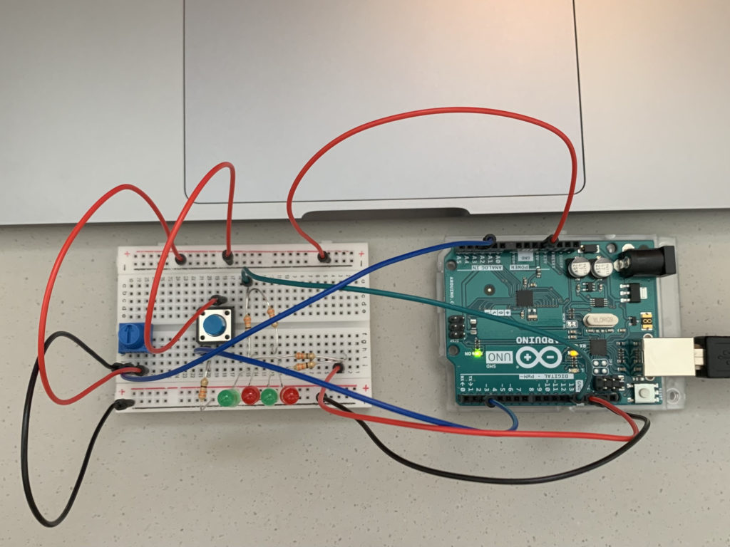
After a few iterations, I was able to settle on a setup that worked:

The row of four alternating red and green LEDs are the Christmas lights; the red LEDs are connected to Pin 13, while the green ones are connected to Pin 12. The colors of the wires match the colors of the connected LEDs. Electricity from the 5V pin flows to both the digital sensor (the switch) and the analog sensor (the potentiometer), from which data goes respectively  to Pin 2 and the A2 pin. All of the circuits, of course, flow back to the GND pin.

As for the code, I first initialized the needed variables and got things started in the setup() function:

//Initialize Variables
int currentButtonState;
int lastButtonState;
int LEDState = 0;
int sensorValue;

void setup() {
  //Initialize Serial
  Serial.begin(9600);
  //Set Pins
  pinMode(12, OUTPUT);
  pinMode(13, OUTPUT);
  pinMode(2, INPUT);
  //Set the Starting State of the Button
  currentButtonState = digitalRead(2);
}

The currenButtonState and lastButtonState variables are crucial to a central feature of my circuit, which is how the button is used to switch between the LEDs’ three different modes (off, on, alternating blinks). For this part of the code, I referred to this tutorial: Arduino Button Toggle LED Tutorial.

The LED’s modes are linked to the LEDState variable; 0 is off, 1 is on, and 2 is alternating blinks. As shown in the code above, LEDState starts at 0, meaning the LEDs are initially off.

Following is the first part of the code in the loop() function:

void loop() {
  //Saves the Last State
  lastButtonState = currentButtonState;
  //Reads the New, Current State
  currentButtonState = digitalRead(2);
  //Sensor Value; 100 is the minimum for the delay interval
  sensorValue = analogRead(A2) + 100;
  Serial.println(sensorValue);
  //Delay for Read Stability
  delay(1);

  //Only Runs When Button is Pressed
  if (lastButtonState == HIGH && currentButtonState == LOW) {
    Serial.println("The button has been pressed.");
    //Change LED State with Each Press
    if (LEDState == 0){
      LEDState = 1;
  } else if (LEDState == 1){
      LEDState = 2;
  } else if (LEDState == 2){
      LEDState = 0;
  }
  //Rest of Code Below
}

As demonstrated in the code, an if statement is used t0 check if the button has been pressed—and when the button is pressed, a chain of nested if else statements are used to change the value of the LEDState variable to the next one in line. Also notable is how the sensorValue is used to store the value collected from the potentiometer with an extra 100 added to it. The reason for this is revealed in the rest of the code:

void loop() {
  //Rest of the Code Above
  //0 = Off; 1 = On; 2 = Alternating Blinks, Delay interval controlled by potentiometer
  if (LEDState == 0){
    digitalWrite(12, LOW);
    digitalWrite(13, LOW);
    }
  } else if (LEDState == 1){
    digitalWrite(12, HIGH);
    digitalWrite(13, HIGH);
  } else if (LEDState == 2){
    digitalWrite(12, HIGH);
    digitalWrite(13, LOW);
    delay(sensorValue);
    digitalWrite(12, LOW);
    digitalWrite(13, HIGH);
    delay(sensorValue);
  }
}

Based on the value of LEDState, a different mode is accessed. sensorValue is used as the parameter value in the delay() functions to determine the length of the interval of each blink; turning the potentiometer counterclockwise will make the LEDs blink quicker, while turning it clockwise will make them blink slower. 100 is added to the value from the potentiometer to determine sensorValue because I determined that 100 would be a good minimum value to set for the delay() function (a parameter of 0 would essentially be no blinking, while anything under 100 is much too rapid).

Here is a video of what the finished project looks like:

Reflections

While I initially struggled to grasp the workings of Arduino and circuits, I feel that I have begun to get a hang of how things work. Tinkering with the kit on my own has allowed me to review and figure things out, and being able to pull this off successfully has been a confidence boost! I feel much more comfortable with Arduino than I was prior to this assignment.

One major part of the project I could improve: using the delay() function has the critical drawback of rendering my program unable to read any button presses that happen while Arduino is paused (making it seem unresponsive). It turns out there is indeed a way to make the LEDs blink without using the delay() function, one that I only found out about after wrapping things up; it will be something to keep in mind as I continue to work with Arduino.

Assignment 5: Unusual Switch

Concept

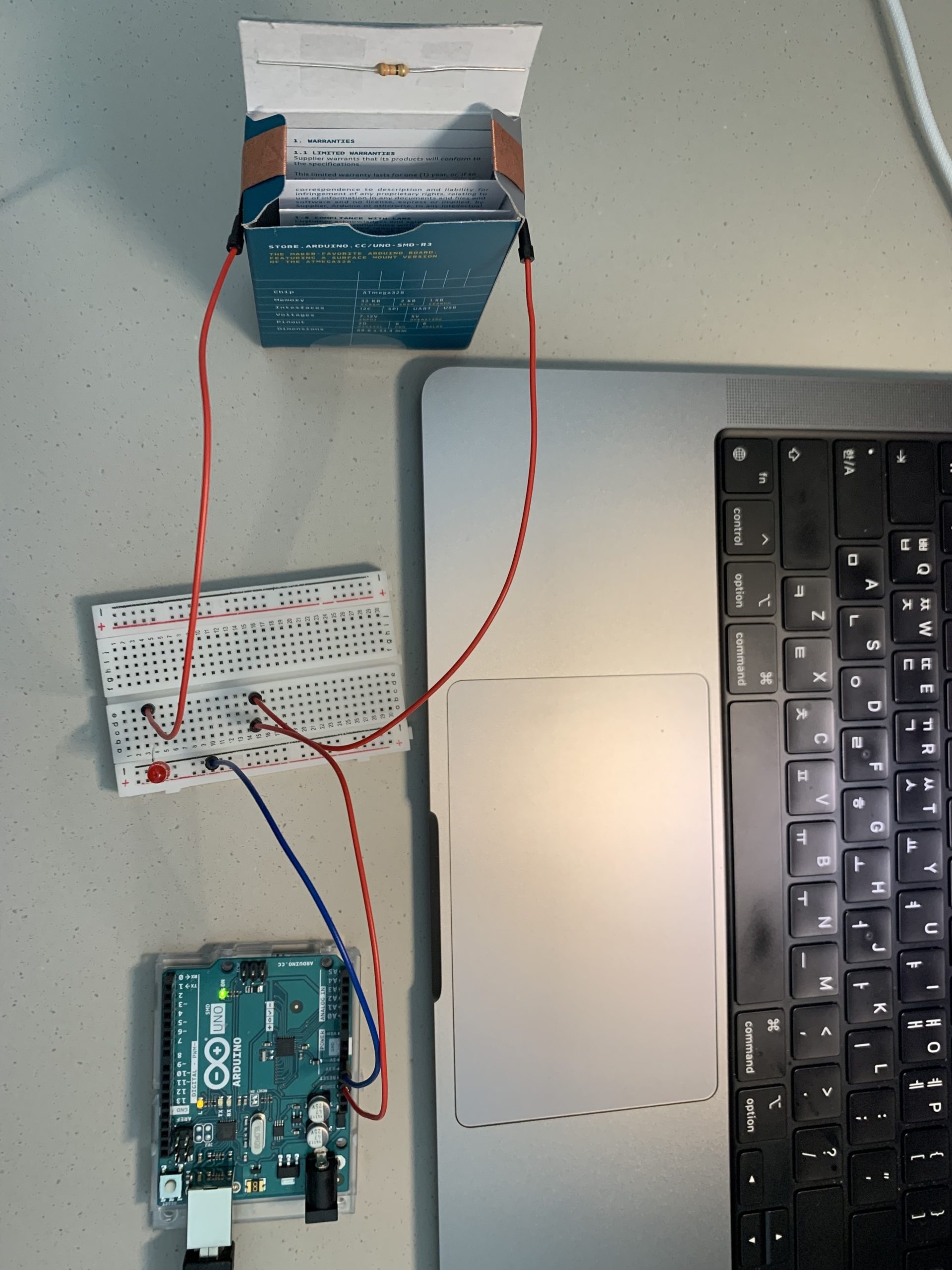
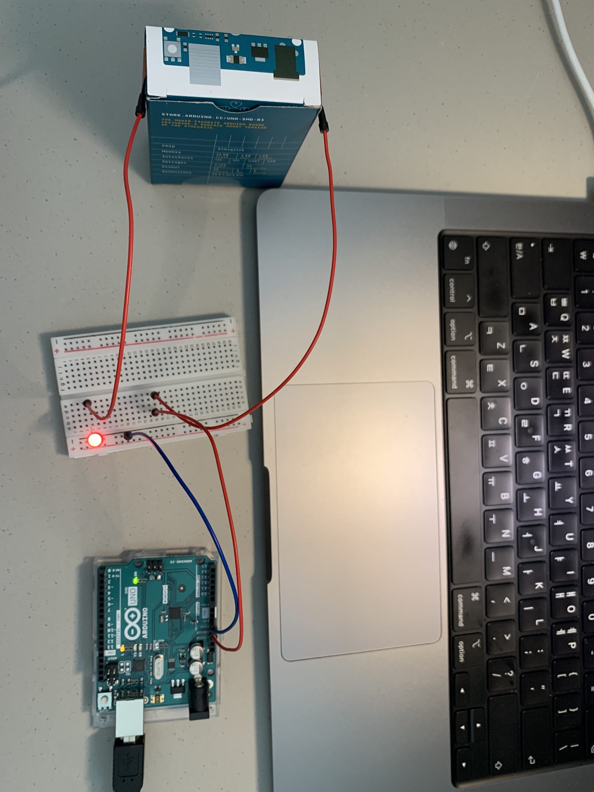
After procuring some conductive fabric from the IM Lab, I was fiddling around with the kit when a thought struck my head: instead of having a wire be dependent on the switch, I could have a resistor play the part. My eyes then turned to the box for the Arduino Uno board lying on its side—it looked quite dejected, emptied of its contents and all on its lonesome. I simply had no choice but to let it play a central role in my contraption. Looking at the box, an idea found itself in my mind: closing the box would act as a trigger for lighting up the LED. To work, then.

Process

After creating a simple circuit composed of four wires, a resistor, and an LED (5V → Wire → Wire → Resistor → Wire → LED → Wire → GND), I removed the resistor and unplugged each end of the two wires surrounding it. I then taped two slivers of the conductive fabric to the two side flaps of the box, creating small openings between the fabric and box within which I could slip in the ends of the wires. The final step was to tape the resistor to the inside of the box so that its tips would touch the fabric on both sides when the box is closed, thus completing the circuit. These pictures should help show what this looks like:

Off…and On!

And also a video:

Reflections

While it initially took me a little time to formulate the concept for my switch, things went quite smoothly after I settled on an idea! It was an exciting moment when the LED lit up as I had intended, akin to the thrill one feels when their code works. On that note, I look forward to what I can make by combining circuits with code—and especially to the doubled sense of satisfaction when things work out!

Midterm – Goomba Spotting

Concept

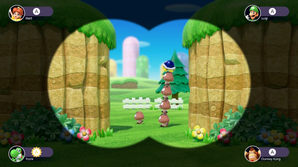
While playing Mario Party earlier this month, I was struck with the idea to recreate one of the game’s many minigames. After some thought, I settled on one named Goomba Spotting, in which players attempt to accurately tally the number of Goombas—a species of mushroom-like beings from the Mario series—that run across the screen. This is what it looks like:

Players try to count the Goombas that pass by on screen.

While it would certainly be a massive challenge unlike anything I had done before, it was one I felt I could tackle at my current level. After mentally dissecting the game into a number of key components, I set out to work.


Challenges and Highlights

I first prepared the images that would be used in the game: one for the background and one for the Goombas. One decision I had made from the start was to have NYUAD be the setting for the game: the premise would be that a Goomba invasion had happened in our beloved institute, and that the two players were “Goomba Spotters” tasked with tallying the Goombas. I edited an image of NYUAD as seen from its entrance into two separate images, a foreground and a background—the Goombas would pass in between. For the Goomba itself, I selected a sprite online and edited the background away.

With the stage now in place, I decided to immediately take on the biggest challenge of coding the Goombas. How would they move? How many should there be? With questions brewing in my head, I created a class specifically for the Goombas and their movement. By adding new functions and adjusting values as needed, I was able to settle on a comprehensive block of code that worked.

One particular highlight from this process was figuring out a way to “stall” the Goombas so that they would come out one by one, instead of all at once. This is the function used to achieve this:

//Create Class for Goombas
class Goomba {
  constructor(){
    this.xPos = 0;
    this.yPos = 492;
    this.xSpeed = random(5, 10);
    this.ySpeed = 0;
    this.check = false;
  }
  //Used to "Stall" Each Goomba to Make Them Come Out in Order
  stall(order){
    if((frameCount - frameCheck) / (25 * (order)) == 1){
      this.check = true;
    }
  }
  //Changes Goomba's Position Based on Speed
  move(){
    if(this.check == true){
      this.xPos += this.xSpeed;
      this.yPos += this.ySpeed;
    }
  }
  //Draws Goomba
  draw(){
    image(photo, this.xPos, this.yPos, 60, 70);
  }
  //There is more code in the class, but it is truncated here to keep things short.
}

This function effectively staggers the Goombas’ initial movement speeds by 25 frames each; in other words, the next Goomba in line will start moving 25 frames after the one before it has started moving. 

(frameCount – frameCheck) is used to calculate the number of frames that have passed since the actual game has started (frameCheck is a variable that I made—it is defined as the frameCount at the time the gameState is set to ‘playing‘); said number is then divided by (25 * order),  in which order is a parameter that corresponds to the “order” of the Goomba (calculated as i + 1).

The result of this division is then checked if it is equal to 1—and if so, this.check is set to true. As seen in the move() function, this.check has to be true in order for the Goomba to be able to move. A small self-congratulatory round of applause was in order.

Another major part of the code is a separate class I created for calculating tallies and results. Each click of a player’s assigned key (A for Player 1 and L for Player 2) is one tally, and this is kept track through this block of code:

//Create a Class for Tally
class Tally {
  constructor(){
    this.p1Number = 0;
    this.p2Number = 0;
  }
  //Keeps Track of Each Press; One Press = One Tally
  checkP1Click(){
    this.p1Number ++;
  }
  checkP2Click(){
    this.p2Number ++;
  }
  //There is more code in the class, but it is truncated here to keep things short.
}

//Function for Checking Key Presses
function keyPressed() {
  //Player 1: A Key
  if (keyCode === 65) {
    tally.checkP1Click();
  }
  //Player 2: L Key
  if (keyCode === 76) {
    tally.checkP2Click();
  }
}

65 and 76 are respective key codes for the A and L keys—so when pressed, the functions checkP1Click() and checkP2Click() are activated. This respectively adds 1 to this.p1Number and this.p2Number, which are the variables used to track the players’ tallies. These tallies are then compared to the actual number of Goombas at the end of the game to calculate the results (these are done through functions that are part of the truncated code mentioned above).

These two classes of Goomba() and Tally() are central to the game, which is in itself brought forth using a function named gameScreen(), which is called when gameState == ‘playing.’ On that note, it must be mentioned that the variable gameState is pivotal to this project, as it is used to transition between the start screen, game screen, and end screen. These three scenes are represented by three separate functions: startScreen(), gameScreen(), and endScreen(), which contain the code needed to bring each screen to life. These functions work in tandem with gameState, which has three values it alternates between: ‘start,’ ‘playing,’ and ‘end.’ The value of gameState is continually checked in the draw() function, and either startScreen(), gameScreen(), or endScreen() is called depending on the respective value. The code for this looks like:

//Draw Function: Displays Different Screen Based on gameState
function draw() {
  //For Start
  if (gameState == 'start') {
    startScreen();
  } //For Playing
  else if (gameState == 'playing') {
    gameScreen();
  } //For End
  else if (gameState == 'end') {
    endScreen();
  }
}
//Code has been abridged for convenience.

The start screen and end screen share an identical template (the same background and gray box is used) with different text. Another coding highlight is present within the background, a gradient made with an interesting function called lerpColor() that I learned anew for this specific task. lerpColor() blends two colors and finds a third color between the two, and the coder can also control how close the interpolated color is to either of the two colors. Using lerpColor() within a for() loop, I painted in thin rectangles that start near the first color (orange) and grow closer to the second color (light blue) with each iteration of the loop, giving off the impression of a gradient:

//Make Gradient Background
  let from = color(255, 135, 0);
  let to = color(0, 240, 255);
  noStroke();
  for (let i = 0; i < 664; i = i + 6.64){
    fill(lerpColor(from, to, 0 + i * 0.0015))
    rect(0, i, 820, 7);
  }

Other highlights include figuring out ways to 1) vary the dialogue in the end screen based on the results (by using variables that functions in Tally() can alter to contain different text depending on the results), 2) change the number of Goombas in each game (by using a variable named randI, the value of which is reset every time the game is played), 3) make the Finish button appear after the game has actually ended (by tying the button to a variable named gameEnd that relies on the position of the last Goomba), and more.

Finally, here is the completed game:


Reflections

Whoa, what a project. Undoubtedly the biggest and toughest one yet—but I made it through! I feel pride in how I was able to achieve what I set out to do without making any major compromises. I admittedly felt incredibly stuck and confused at many points, unable to pull off certain effects I was aiming to implement (successfully stalling the movement of Goombas was especially challenging). Despite said difficulties, I was ultimately able to find a solution through each and every one of the major challenges I set out to tackle.

It’s been quite the journey! I started the class with a nearly blank slate, having only minimal coding experience (none with Javascript). Looking back, I’ve come quite far; it was a magical experience to be able to make something of my own that I personally envisioned and designed. And this will certainly not be the last.

Midterm – Progress Check

Concept

The current idea that I have for my midterm game is a recreation of a minigame from Mario Party named Goomba Spotting. In the game, players are tasked with accurately tallying the number of Goombas (mushroom-shaped creatures from the Mario series) that run across the screen. The Goombas run at varying speeds and overlap each other to make it difficult to count them. The hope is that I will be able to reproduce these mechanics and effects in p5js!

Progress As of Now

My main focus has been on replicating the main mechanic of the game—namely, the Goombas and their “walking” behavior. After much trial and error, I’ve managed to figure out a way to make things work. Crucial to this process was how I created this class specifically for the Goombas:

//Create Class for Goombas
class Goomba {
  constructor(){
    this.xPos = 0;
    this.yPos = 492;
    this.xSpeed = random(5, 10);
    this.ySpeed = 0;
    this.check = false;
  }
  //Used to "Stall" Each Goomba to Make Them Come Out in Order
  stall(order){
    if(frameCount % (30 * order) == 0){
      this.check = true;
    }
  }
  //Changes Goomba's Position Based on Speed
  move(){
    if(this.check == true){
      this.xPos += this.xSpeed;
      this.yPos += this.ySpeed;
    }
  }
  //Draws Goomba
  draw(){
    image(photo, this.xPos, this.yPos, 60, 70);
  }
  //Constantly Randomizes Goomba Speeds
  random(){
    if(frameCount % 20 == 0){
      this.xSpeed = random(0, 15);
    }
  }
}

This class then works in tandem with an array and a for() loop in the setup() function to generate a random number of Goomba objects—their appearances and movements on the screen are then facilitated through another for() loop in the draw() function:

//State Variables
let goomba = [];
let randI;

function setup() {
  //Generate Random Number for # of Goombas
  randI = random(15, 30);
  randI = Math.round(randI);
  //Generate Multiple Values in Array for Multiple Goombas
  for (let i = 0; i < randI; i++){
    goomba[i] = new Goomba();
  }
}

function draw(){
  //Functions for Each Goomba
  for (let i = 0; i < randI; i++){
    goomba[i].stall(i + 1);
    goomba[i].draw();
    goomba[i].move();
    goomba[i].random();
  }
}

And now, the Goombas in motion:

Moving Forward

I’m glad that I was able to figure out how to make a major component of my game work! There’s obviously a lot more left to do, ranging from creating the start/end screens and implementing the Goomba-tallying system—but my success so far gives me hope that I will be able to make my concept come to life! Here goes.