[Assignment 3] Particle Simulator

Concept

For this assignment, I have created a particle simulator, in which small particles move away from the cursor and return to their initial positions. As the particles are in motion, their color will change. Recently, I have read several papers regarding electromagnetic forces and quantum fields. This project is inspired by the electromagnetic interactions between charged particles. I pictured small localized particles on a field, on which the particles are repelled by an external force (the cursor). The particles will then return to their initial position because they are most stable on those points. The color red means the particles are stable; the color blue means the particles are unstable.

Code

I began writing codes for declaring a class for small particles. Each particle will store 5 different pieces of information about their X and Y coordinates of their initial positions, X and Y coordinates of their current positions, and the color that will be used to set the stroke color.

class spacePoints {  //Declare class
  constructor(posX, posY) {
    this.posX0 = posX;  //Original X coordinate of the point
    this.posY0 = posY;  //Original Y coordinate of the point
    this.posX = posX;   //Current X coordinate
    this.posY = posY;   //Current Y coordinate
    this.color = 255;   //Color of the point when drawn
  }

The most challenging codes to write in this project was a class method, which updates the position of the particles depending on the cursor position. Using dist(), I measured distance between a particle and the cursor. If the distance is smaller than the defined threshold, the particle must be repelled. To do this, a vector that is always directed away from the cursor was declared. Then, the magnitude of the vector was modified to make its magnitude increase as the cursor gets closer to a particle. Since the particle is in motion, and thus, unstable, the particle’s color property is also modified.

If there is no cursor near a particle, a particle is moved back to its initial position. Another vector that points towards a particle’s initial position was created. Based on this vector, a particle’s position is updated.

movePoint() {  
    let cursorDist = dist(this.posX, this.posY, mouseX, mouseY); 
    if (cursorDist < 100) { 
        let dVec = createVector(this.posX - mouseX, this.posY-mouseY); 
        dVec = dVec.setMag(100 / dVec.mag()); 
        this.posX += constrain(dVec.x, -20, 20); 
        this.posY += constrain(dVec.y, -20, 20); 
        this.color = 0; 
    } else { 
        if (abs(this.posX - this.posX0) > 1 || abs(this.posY !=       this.posY0) > 1) { 
        let dVec = createVector(this.posX0 - this.posX, this.posY0 -    this.posY);
        dVec.setMag(1);
        this.posX += dVec.x; 
        this.posY += dVec.y;
      }else this.color=255; 
    }
  }

In the end, I wrote a short method that draws a particle based on the canvas. One noticeable thing is that the stroke color will change depending on a particle’s color property.

 drawPoint() {  //Draw a spacePoint
    noFill();
    stroke(this.color,125,125);
    strokeWeight(3);
    circle(this.posX, this.posY, 8);
  }

Click listener is also used, so the user can freely add particles on specific points they click on.

function mouseClicked() {  //When mouse is clicked
  append(pArr, new spacePoints(mouseX+random(-5,5), mouseY+random(5,-5)));  //Generate new spacePoint at where the mouse is clicked. Store it in pArr[]
  pNum++;  //Increase number of current number of spacePoints by 1
}

The draw function is rather very simple because all calculations are done by the functions and objects.

function draw() {
  background(0);

  for (let i = 0; i < pNum; i++) { 
    pArr[i].movePoint();  //Update positions of spacePoints in pArr
    pArr[i].drawPoint();  //Draw spacePoints in pArr on the canvas
  }
}

Reflection / Future Improvements

I am very happy about my project’s complex mathematical logic behind the simple appearance. I initially added lines that show the current direction and velocity of the particle’s motion, but I had to remove the lines to keep my project look simple. This is the first project that I did not use translate()  to handle coordinate calculations, which I found surprisingly easy without shifting my origin to the canvas center.

If I have another opportunity to work on this project, I would like to change and improve upon these:

  1. Optimization. Though code seems to run smoothly regardless of the number of particles, there are rare moments the code takes time to start. I believe this problem occurred because I used vectors for angle calculations. Instead of calculating angles via vectors, the program may run faster if mathematical expressions are used.
  2. Collision Detection. The project will look more interesting if each particle interacted with the other. If each particle has collision detection features, the particle simulator will be more realistic. However, because collision detection require more computing power, the codes must be optimized before adding this feature.

 

[Assignment 2] Glitchy Dragon Curves

Concept

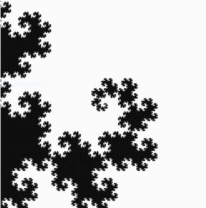
For this assignment, I have created multiple “glitchy” dragon curves, rotated with respect to the canvas center. The dragon curve is a widely known space-filling curve, meaning multiple of these curves can cover the entire 2D plane without overlapping. Not to mention, the curve is a fractal!  I first encountered this curve in my freshman year in high school, and the experience was mesmerizing. For this reason, I decided to draw dragon curves as soon as I read the assignment description.  Although the curve alone is indeed awe-inspiring, I added a glitchy appearance to the curves to make them look more interesting. The picture below is a single dragon curve without a glitchy appearance.

Code

I spent most of the time finding and coding an algorithm to create dragon curves. Fortunately, the algorithm was very intuitive because dragon curves are formed by “folding” a line segment 90° in left or right directions. I first declared an array (dirArr) that stores these directional data, which describes how line segments will be folded.

let dirArr = []; //Direciton Array storing Left or Right turn for each line segments

A function was created to fill this array using a recursive algorithm I have coded (1 indicates a right turn and -1 indicates a left turn). The default size of dirArr is 1, and it contains 1, meaning a right turn. As iteration number increases, dirArr will store more directional data, making curve more complex. The algorithm fills dirArr in this way:

[1] -> [1, 1,-1] -> [1,1,-1,1,1,-1,-1] -> [1,1,-1,1,1,-1,-1,1,1,1,-1,-1,1,-1,-1]

Each array represents directional data stored in dirArr of different iterations.

  1. For each iteration, the algorithm adds 1 at the end.
  2. Then, directional data that were in the previous iteration’s dirArr (red) are copied into a temporary array.
  3. Copied data in the temporary array are reversed (1 to -1 and -1 to 1). This data will then be added to dirArr in reverse order (blue).
  4. Steps 1,2, and 3 will be done until given iteration of dirArr is achieved (recursion).
function fillDirArr(iteration, myArr) {
  //Store Left or Right turns into dirArr. 1 = Right turn, -1 = Left
  count++;
  let tempArr = myArr.slice(); //tempary array to store dirArr
  myArr.push(1);
  let tempArrLength = tempArr.length;
  for (let i = 0; i < tempArrLength; i++) {
    let currDir = tempArr.pop(); //Read tempArr from the end
    myArr.push(-1 * currDir); //Reverse direction and push to currDir
  }
  if (iteration == count) {
    count = 0;
    dirArr = myArr;    
    return;
  } else fillDirArr(iteration, myArr); //recursion until given iteration
}

Based on dirArr, lines will be drawn using a function. This function simply draws multiple line segments with a given length. One challenging part of drawing curves was letting the code know which direction is left or right. For example, when a line segment is heading upward, making a right turn and drawing another segment can be done by line(X,Y, X+length,Y). On the other hand, when a segment is heading leftward, making a right turn and drawing another segment can be done by line(X,Y,X, Y-length). As shown above, rotating a segment left or right turn must also consider a segment’s current direction. I solved this problem by using 1s and -1s as weights. Keeping track of the sum of 1s or -1s whenever a line segment turns allowed me to calculate the current direction of a segment. Simply draw lines in random directions and add up 1s or -1s depending on the direction of the turn. In the end, you will see the result to be:

  • 0, when a segment is going up
  • 1 or -3, when a segment is going right
  • -1 or 3, when a segment is going left
  • 2 or -2, when a segment is going down

round(random(0,8*L)) was used to give the curve a glitchy look by slightly changing the ending coordinates of the lines.

function drawDragonCurve(X, Y, L) {
  let dirSum = 0; //1 or -1 act as "weights".
  for (let i = 0; i < dirArr.length; i++) {
    let currDir = dirArr[i];
    dirSum = (dirSum + currDir) % 4;
    if (dirSum == 0) {
      //UP
      //line(X, Y, X + L * currDir, Y);
      line(X, Y, X + round(random(0,5*L)) * currDir, Y);
      X += L * currDir;
    } else if (dirSum == 1 || dirSum == -3) {
      //RIGHT
      //line(X, Y, X, Y + L * currDir);
      line(X, Y, X, Y + round(random(0,8*L)) * currDir);
      Y += L * currDir;
    } else if (dirSum == -1 || dirSum == 3) {
      //LEFT
      //line(X, Y, X, Y - L * currDir);
      line(X, Y, X, Y - round(random(0,5*L)) * currDir);
      Y -= L * currDir;
    } else if (dirSum == 2 || dirSum == -2) {
      //DOWN
      //line(X, Y, X - L * currDir, Y);
      line(X, Y, X - round(random(0,5*L)) * currDir, Y);
      X -= L * currDir;
    }
  }
}

Reflection / Future Improvements

This assignment was very entertaining to work on because I have always wanted to make a dragon curve. Although the code required tons of logical thinking and calculations, I have managed to create a very satisfying digital art. When I finished the code, I was very happy to see my dragon curves filling my canvas without overlapping (when there is no glitchy effect).

My program seems to operate without any errors, but it needs optimization. Due to the complexity of the calculation using an array, the code is slow. For this reason, I removed the interactive aspect of the code. In the future, I would like to find a faster and more efficient way to draw dragon curves. When my code is finally fast, I would be able to make dragon curves to be interactive.

[Assignment 1] Self Portrait

Concept

For this assignment, I created a self-portrait using p5js. Various shapes (ellipses, triangles, arcs, and splines) were used to make a portrait of myself. This project contains a user interactive feature, in which the color wheel behind the portrait rotates as cursor moves. Not to mention, once the cursor rotates fast enough, color wheels will begin to randomly change for 2 seconds. Thick lines (strokes) and vibrant colors are used to make this portrait appear like a pop art piece.

Code

Writing codes for the hairs was the most challenging part of this project. To draw my hair, I had to read through the p5js reference page (https://p5js.org/learn/curves.html). In the end, I used spline lines to make custom shapes. A considerable amount of time was used to draw even a single spline line because it required coordinates of all points it passes through.

Code for hairs using spline lines:
//Left part of the hair
fill(0);
stroke(0);
beginShape();
curveVertex(314, 192);
curveVertex(302, 215);
curveVertex(292, 250);
curveVertex(222, 255);
curveVertex(227, 205);
curveVertex(247, 180);
curveVertex(277, 160);
curveVertex(307, 155);
curveVertex(327, 163);
curveVertex(327, 180);
curveVertex(324, 188);
curveVertex(314, 192);
endShape();
//Right part of the hair
beginShape();
curveVertex(324, 185);
curveVertex(326, 175);
curveVertex(337, 170);
curveVertex(366, 177);
curveVertex(374, 198);
curveVertex(375, 225);
curveVertex(372, 232);
curveVertex(362, 210);
curveVertex(347, 200);
curveVertex(324, 185);
endShape();

Another challenge I confronted while working on this project was the translation and rotation of reference points (axis). I translated the origin from the top-left corner to the center of my canvas because color wheels had to rotate around the portrait at the center. Yet, I noticed return values of mouseX and mouseY are not affected by the translation; therefore, I had to manually adjust cursor coordinates as shown below:

let mouseVecCurrent = createVector(mouseX - 300, mouseY - 300);

I expected rotate() to simply rotate objects without altering the axis, but p5js uses a rotation matrix, which means the whole axis will rotate with the object. For this reason, I had to reset the reference point before drawing any shapes:

rotate(radians(350)); //Reset the reference point

To create a responsive color wheel, I had to write several lines of code that calculate the position and rotational speed of the cursor. To do this, I compared current position and previous position of the cursor (pWinMouseX and pWinMouseY are functions that return cursor position in the previous frame). Then, I wrote some conditional statements to determine if the color should change based on the calculated rotational speed.

let mouseVecCurrent = createVector(mouseX - 300, mouseY - 300); //Vector holding current mouse position
let mouseVesPrev = createVector(pwinMouseX - 300, pwinMouseY - 300); //Vector holding previous mouse position

let mouseAngle = mouseVecCurrent.heading(); //Angle of mouse pointer relative to the origin
let mouseAngularV = 9 * abs(mouseAngle - mouseVesPrev.heading()); //Angular velocity of the cursor

//If cursor is rotating rapidly enough around the origin, set colorChange to true. OR, if colorChange is already and it has not been 2 seconds since the last rapid rotation, keep colorChange as true.
if (mouseAngularV > 53 || (colorChange && millis() - t < 2000)) {
if (!colorChange) { //If colorChange is false, set t to current millis time.
t = millis();
}
colorChange = true;
}else colorChange = false;

With the help of trigonometry and cursor information, I made color wheels that follow the cursor using triangles. The triangles were placed using for loop and their colors were randomly assigned using random()  function.

for (let i = 1; i <= divNum; i++) {
fill(i * 10 + 70, 3 * i + 125, 5 * i); //Default color regardless of the cursor movement.
if (colorChange) fill(random(255), random(255), random(255)); //If colorChange is true, wheel colors will totally be random for 2 seconds.
triangle(
0,
0,
700 * cos(((i - 1) * 2 * PI) / divNum + mouseAngle),
700 * sin(((i - 1) * 2 * PI) / divNum + mouseAngle),
700 * cos((i * 2 * PI) / divNum + mouseAngle),
700 * sin((i * 2 * PI) / divNum + mouseAngle)
);
}

Reflections / Future Improvements

Although I faced some challenges making this self-portrait, the project was very fun and exciting to work on. My portrait may not be perfect, but I am very satisfied with the project and willing to continue working on more intricate codes in this course.

In the future, I would like to write a piece of code that will open and close the mouth when the cursor is clicked. Adding a portion of my upper body that can interact with user input may also be interesting improvements to make in the future.