
Concept
Throughout the semester, I’ve created projects that, in a sense, gamified concepts in Biology. Back when I worked on my Assignment 2, I had expressed a desire to allow users to select multiple color options for the bacteria. So, this project grew out of that desire, in addition to giving people a chance to practice very basic Synthetic Biology / Microbiology.
In essence the concept is simple. There are six prepared agar plates. Additionally, there are six fluorescent proteins: Green Fluorescent Protein [green], mCherry [pinkish-red], mOrange [orange], mKO [yellow], mCerulean [cyan], and Blue Fluorescent Protein [BFP]. All of these proteins fluoresce naturally under UV light and are not usually produced by bacteria. Instead, they are obtained from bioluminescent animals and can thus be used as a method to verify whether a certain gene editing technique worked in bacteria. But that biology-heavy introduction aside, the idea was that users select the fluorescent protein-modified bacteria they want and “pipette” them into the corresponding plate. Then, they can incubate the bacteria to watch them grow and toggle the UV light to actually see the fluorescence.
Implementation
Interaction Design
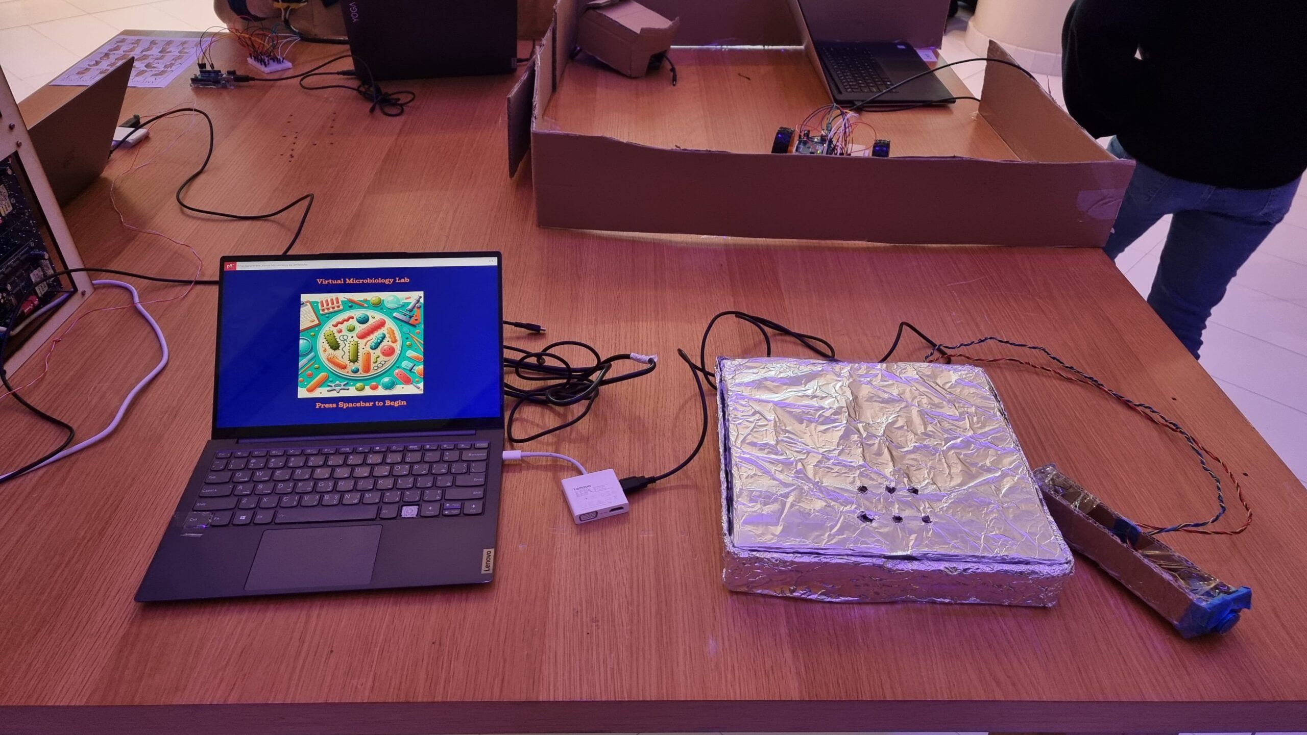
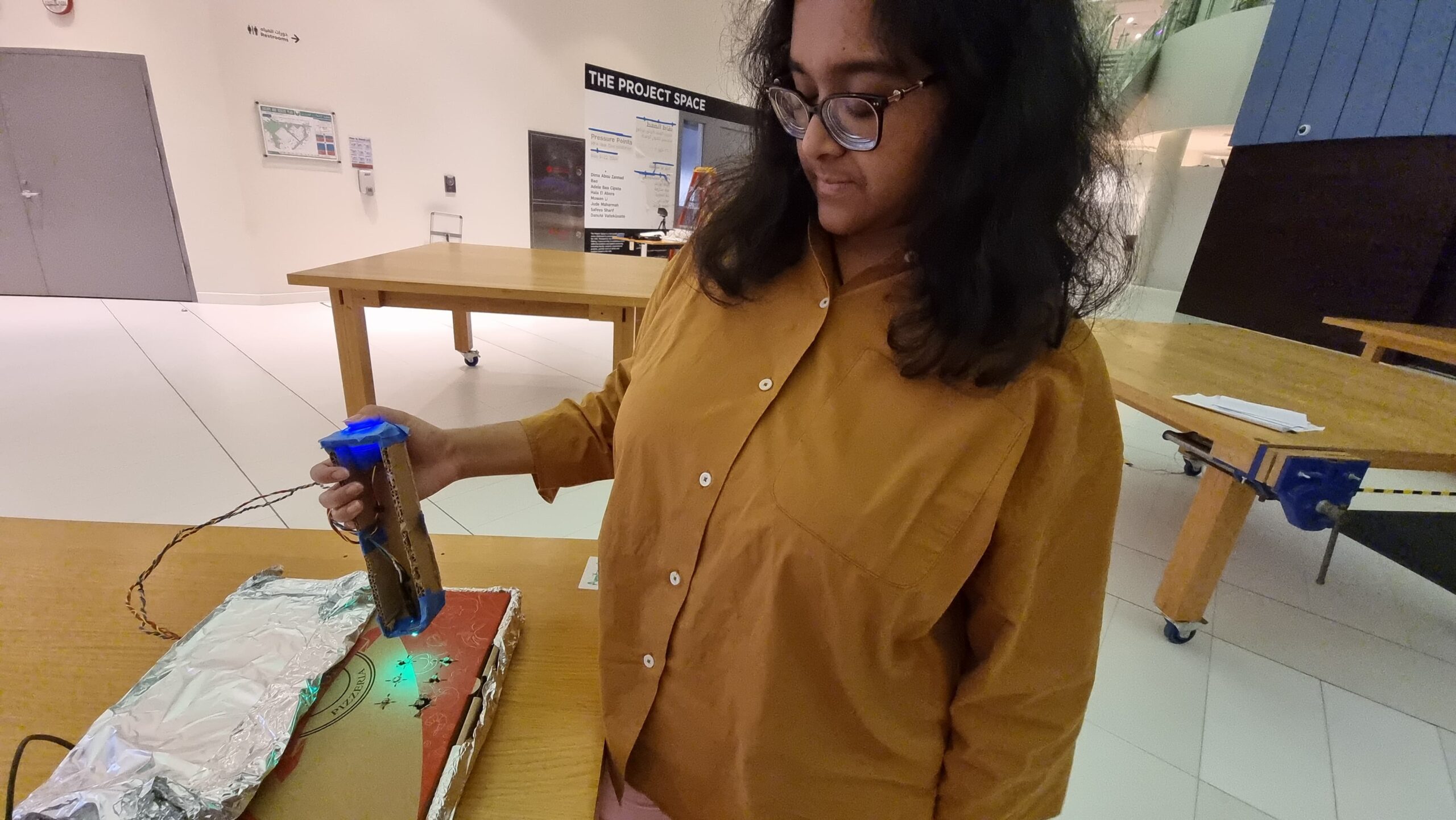
As mentioned above, the interaction design has two main parts: the laptop-focused part, and the physical prototype part. On the laptop, the user can press on-screen buttons to change the fluorescent protein, incubate the bacteria already plated, toggle the UV lamp, and dispose of the plates. On the physical prototype, the user has to bring the pipette to one of six holes (each of which contains a hidden photoresistor) and press a button to “dispense” bacteria. The idea is that the user controls which color of bacteria they want to grow on which plate.
Arduino Code
The Arduino code was relatively simplistic, as its main purpose was to read the values from the hidden photoresistor and send them to p5. The secondary function was to receive color values from p5 and control an RGB LED with it to glow with the corresponding color.
phot0 = analogRead(A0);
phot1 = analogRead(A1);
phot2 = analogRead(A2);
phot3 = analogRead(A3);
phot4 = analogRead(A4);
phot5 = analogRead(A5);
if (phot0 - phot0init > 100) {
  Serial.println("0");
}
if (phot1 - phot1init > 300) {
  Serial.println("1");
}
if (phot2 - phot2init > 300) {
  Serial.println("2");
}
if (phot3 - phot3init > 300) {
  Serial.println("3");
}
if (phot4 - phot4init > 300) {
  Serial.println("4");
}
if (phot5 - phot5init > 300) {
  Serial.println("5");
}
The above code basically detects light intensity crossing a certain threshold value above the background light intensity. The reason why pin 0 had a lower threshold was because the associated photoresistor appeared to be more sensitive to light and reached near maximum intensity even under ambient light conditions. Three separate photoresistors behaved that way, so I decided to just change the code instead. It is likely that all three photoresistors were of the same type (i.e. one that was different from the others).
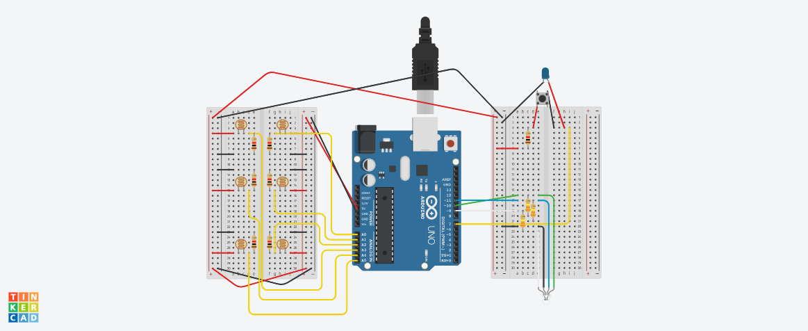
Below is my (highly confusing) assembly diagram of the project, as created using TinkerCAD.

p5 Code
The p5 code was mostly based on my old code from Assignment 2. However, I had to modify it quite a bit to both work with Serial Communication and also restrict the agar growth to specific plates rather than the entire area of the sketch. Like last time, I used randomGaussian() for the growth. I used this instead of Perlin Noise as I rather liked the higher degree of randomness the Gaussian random gave me, as the Perlin Noise did tend towards aggregation rather than spread, as expected.
Also, to avoid colonies from appearing beyond the plate borders, I just used an if() statement to only display those colonies that were generated within borders. While I originally wanted to use a while() loop to truly restrict generation to within the plate, I soon discovered that a while() loop interfered with Serial Communication, thus causing the program to crash. Since a minimum of 5 and a maximum of 30 colonies were generated every frame, or 60 times per second, I felt that the few colonies leaving the plate borders that would not be displayed wouldn’t really be missed.
for (let i = 0; i < numColonies; i++) {
  // Gaussian random to ensure aggregation towards center
  colonyX = randomGaussian(cultures[d].x, spread);
  colonyY = randomGaussian(cultures[d].y, spread);
  colonyR = random(2, 15);
  if (
    dist(
      colonyX,
      colonyY,
      plates[cultures[d].loc].x,
      plates[cultures[d].loc].y
    ) <=
    plates[d].diameter / 2 - colonyR - 3
  ) {
    strokeWeight(3);
    if (uv) {
      stroke(cultures[d].border);
      fill(cultures[d].col);
    } else {
      stroke(colonyBorder);
      fill(colonyColor);
    }
    ellipse(colonyX, colonyY, colonyR);
  }
}
Serial Communication
Serial Communication in this project was two-directional.
From the p5 sketch, the RGB values of the fluorescent protein colors were sent to the Arduino, which would use these as inputs for red, blue, and green light. I converted the hexadecimal color value to decimal using parseInt() which I learned to use from this tutorial.
let colRgb = hexToRgb(colonyUVColors[currentProt]);
let sendToArduino = colRgb[0] + "," + colRgb[1] + "," + colRgb[2] + "\n";
writeSerial(sendToArduino);
From the Arduino component, the information about which photoresistor had crossed the threshold and was thus the plate on which the user had “dispensed the bacteria” was communicated to the p5 sketch. As explained earlier, this information would only be sent when the light intensity crossed a certain value above background light intensity.
p5 Sketch
Fullscreen Version: https://editor.p5js.org/amiteashp/full/nFftrYqe_
Challenges Faced
There were numerous challenges faced. I enumerate some of them below.
1) To detect? Or not to detect?
As anyone who uses photoresistors (or any kind of variable resistance sensors really) must know, photoresistors have wildly inconsistent results. Not just that, since their resistance changes according to light intensity, any changes in background light intensity would also potentially trigger false positives, or could even mask actual detections leading to false negatives. Both are bad.
There are two ways of combatting this. The first is to create an enclosure that minimizes background light intensity. A “dark room” as such. My original plan included this in some aspect, as I had planned to build a mini version of a laminar flow hood as the housing for the project. However, due to my lack of any abilities in fabrication, this was out of the question.
So, the next solution lies in code. Instead of trying to detect light intensity above a certain threshold, using the difference in intensity between background light intensity and the light to be detected would be a better solution. So, I decided to put statements asking the Arduino to measure light intensity at startup through the setup() function. But this presents another problem, as you might have guessed. How would I account for changing light intensity during runtime? This could be done by using the button output (the one the user was pressing to pipette) as a condition for when the actual light intensity was being sensed, and otherwise continually detecting background light intensity while the user did not press the button. This actually worked surprisingly reliably, even in weird lighting conditions.
2) Watch me crank that (solder) boy
Soldering was a pain. It looks easy from the outside but I was clearly doing something wrong because making 8 solder connections took me 2.5 hours. One mistake that I discovered I was doing is that in order to “beautify” the solder, I was trying to melt it a bit so that it flowed around the wire better and looked smoother, but the whole thing would melt off and drop unceremoniously. I quickly learned not to do that.
3) If it can’t be fixed by tape, you’re not using enough
As mentioned in my Resources Used section, much of my project is held together with a ton of Scotch tape. I mean, half of an entire roll of Scotch tape. I initially wanted to join the cardboard segments making up the pipette with hot glue, but I quickly discovered that hot glue guns wouldn’t work too well. Not because of the strength of hot glue (hot glue was strong enough), but because the cardboard itself was too weak to handle shear stress from being pressed on while only being linked using hot glue to one/two joints. Tape allows for more surface area of contact and also holds the pieces together like a rubber band would instead of just creating a joint. Also, a bunch of tape was used to hold the aluminium taut against the pizza box both to prevent crinkles and also to avoid the foil itself from shifting around and covering the potentiometer windows.
4) Serial communication: More drama than Hindi TV serials
Serial Communication. It’s a useful tool to create projects linking digital artwork on p5 to physical processes through an Arduino.
But it requires so much bug-fixing to get right.
Right off the bat, as described earlier, a while() loop to keep regenerating random positions that were only within disc borders, while working perfectly fine in a p5-only situation, would crash as soon as it came to Serial Communication, most likely because the while() loop interfered with the Serial receiving/sending of data. This required me to switch to an if() statement to only display those colonies that generated within the plate borders, using the dist() function to calculate distance between centers of colonies and plates.
Also, I noticed that occasionally, Serial communication would stop entirely between the p5 and Arduino components. This, I found, was because my code initially sent a number associated with each light sensor when the corresponding light sensor detected the LED. What happens if it doesn’t detect the LED? You’re right, the Arduino stops sending data, breaking the Serial Communication. This, I fixed by asking the Arduino to send an arbitrarily picked ‘6’ whenever no sensor detected the LED.
The final challenge in fact couldn’t be solved by me. I noticed both during User Testing and the show itself that if the user switched colors too quickly (as excited users wanting to try out the different colors are wont to do) Serial lagged on the Arduino side and the LED would display a color associated with a different protein. The time taken to recover gradually increased with runtime, eventually reaching a longest period of 1 minute of recovery time. I found that p5 was indeed sending the correct information with virtually no delay, but without the ability to get Serial callouts from the Arduino while Serial Communication was running meant that I could not identify what was causing the lag in the Arduino.
User Testing
Reflections
Overall, I’m rather proud of my project. It allowed me to convey my love for Biology and allowed people, irrespective of their background, to try their hand at a simple experiment, without requiring any prior lab prep work or worry of contamination and other challenges when it comes to growing bacteria. Also, the simulation was a lot faster than actual bacteria growth (taking E. coli for example, at full growth, each second is equivalent to about 6 hours). Seeing the excited faces at the IM showcase as the fluorescence under UV was revealed to them was (as cheesy as it sounds) worth all the time I spent on this project. That I would say is the aspect I am most proud of. But other than that, I am particularly proud of my way of detecting the LED light using a difference in light intensity method than a raw threshold, as it eliminated the biggest possible source of variation.
However, there is definitely room for improvement. Most of what I include below comes from feedback actually given to me during the IM showcase, or from behaviors that I observed.
- The project was essentially not very intuitive. While I did have a poster with written instructions, like all other written forms of instruction, it was ignored, thus leaving most users confused about what to do without my assistance. The instructions being unclear also didn’t help.
- The interaction could flow better. I could map the change in fluorescent proteins to the keyboard instead of mouse clicks as (a) a lot of MacBook users kept accidentally right-clicking on my Windows laptop due to the differences in what is sensed by each device’s trackpad; and (b) most people stuck to the same color for all six plates as they forgot or did not bother with changing the color.
- As some of my Biology major friends pointed out, it would be cool if I had six tubes with six LEDs of different colors representing each of the fluorescent proteins. And then, instead of selecting the protein from the screen, I could potentially ask the user to “pipette” from one of the tubes and into each well, just like in a real Biology lab. However, this would require both an RGB sensor, as well as a way to distinguish between pipetting in and out. One button with two different depths (like in real pipettes) wouldn’t work, and two separate would be too cumbersome to hold and press. But, it would definitely increase the immersion if possible.
Resources Used
Most of the electronics were from the base Sparkfun Arduino Uno Rev3 SMD kit. I had to borrow additional photoresistors and an arcade button from the IM lab consumables for the photoresistors. Additionally, I borrowed solid core wires and solder to extend my connections and electrical tape to insulate them.
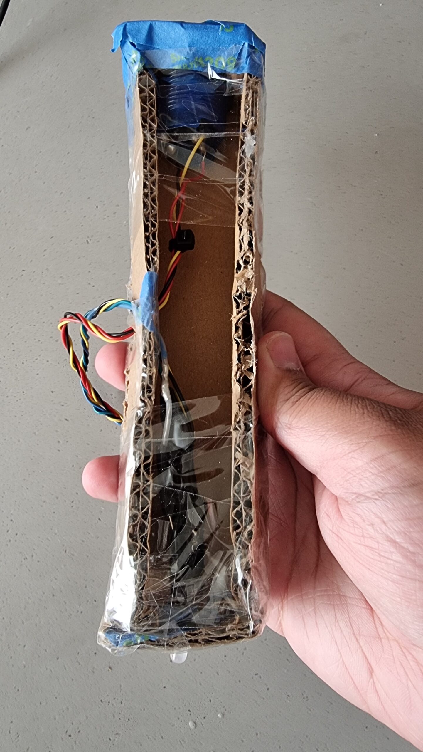
For the physical prototype itself, the pipette was made of cardboard from the IM lab held together with a LOT of tape a hole was punched into one side of the pipette for the wires, and at the bottom for the LED. A larger hole was made at the top for the arcade button.
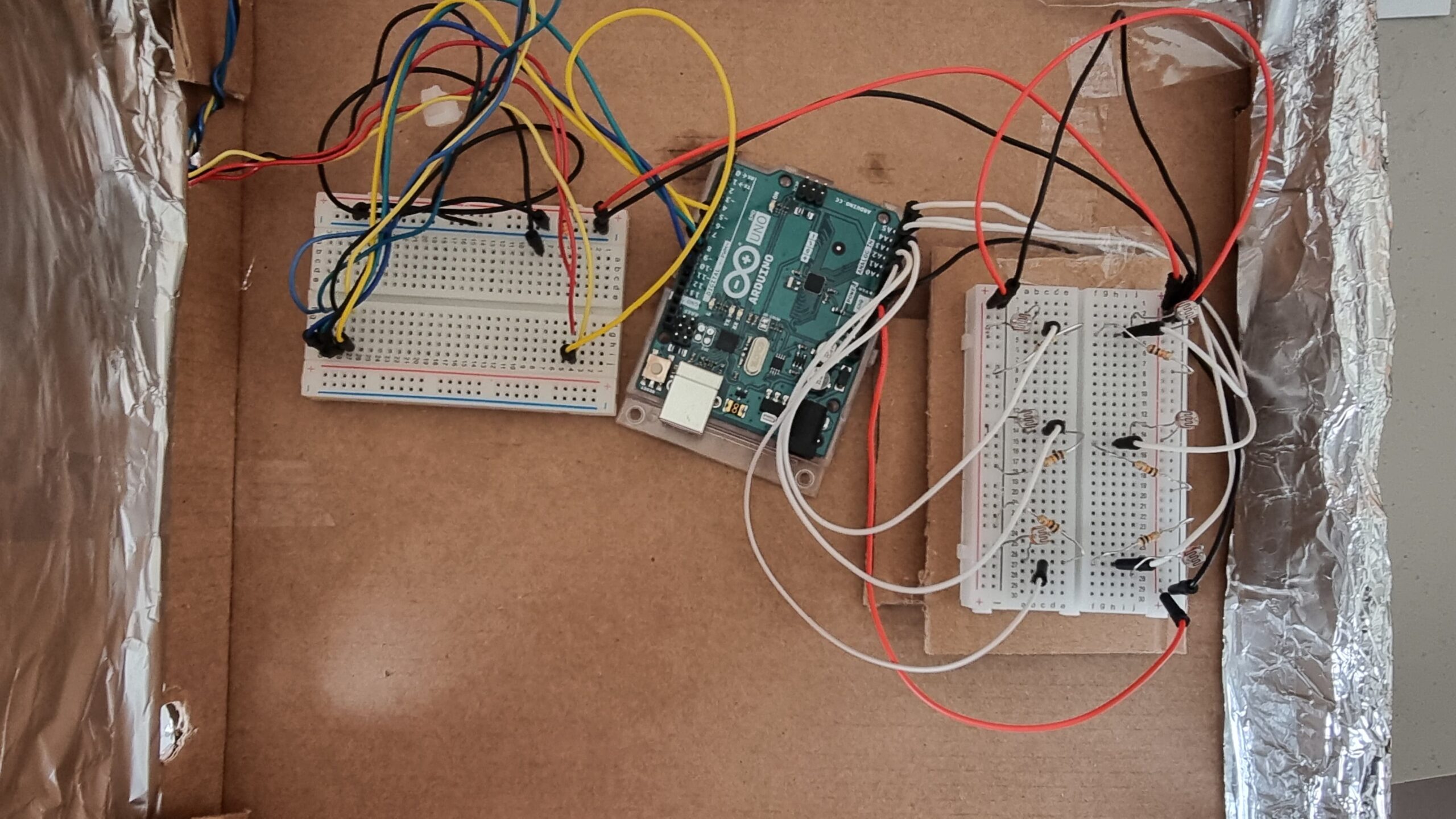
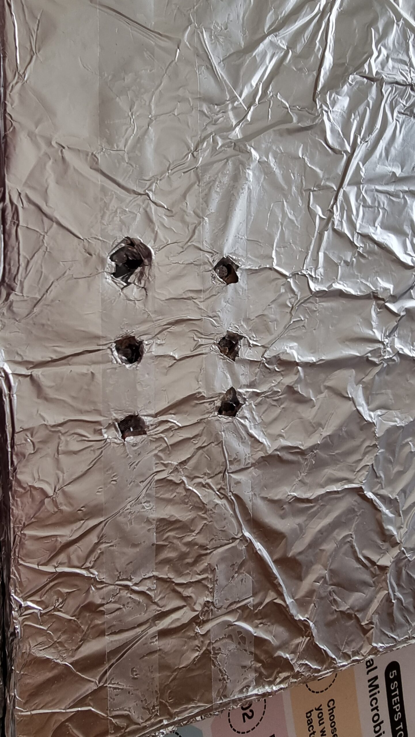
The main working surface was based on a pizza box that was covered in foil and punched with six holes to serve as windows for the photoresistors. All of my circuitry went into the pizza box, which would make it convenient to make any quick fixes. I could just open the box and work on it rather than have to cut anything out of a more permanent casing.

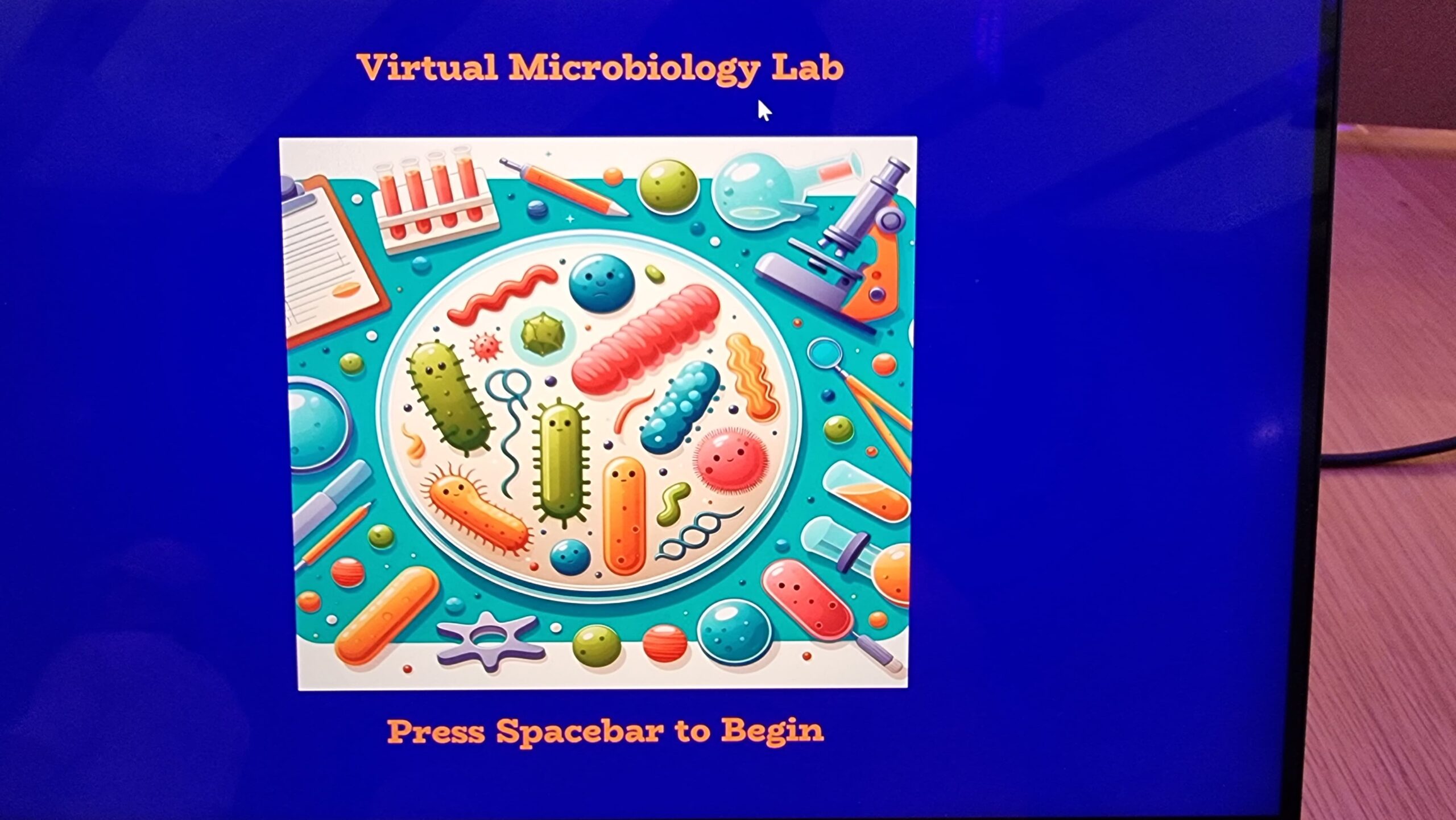
Software side, the cover image was generated using DALLE3, while the images of the fluorescent proteins were obtained from the Protein Data Bank (PDB) maintained by the Research Collaboratory for Structural Bioinformatics (RCSB).
IM Showcase
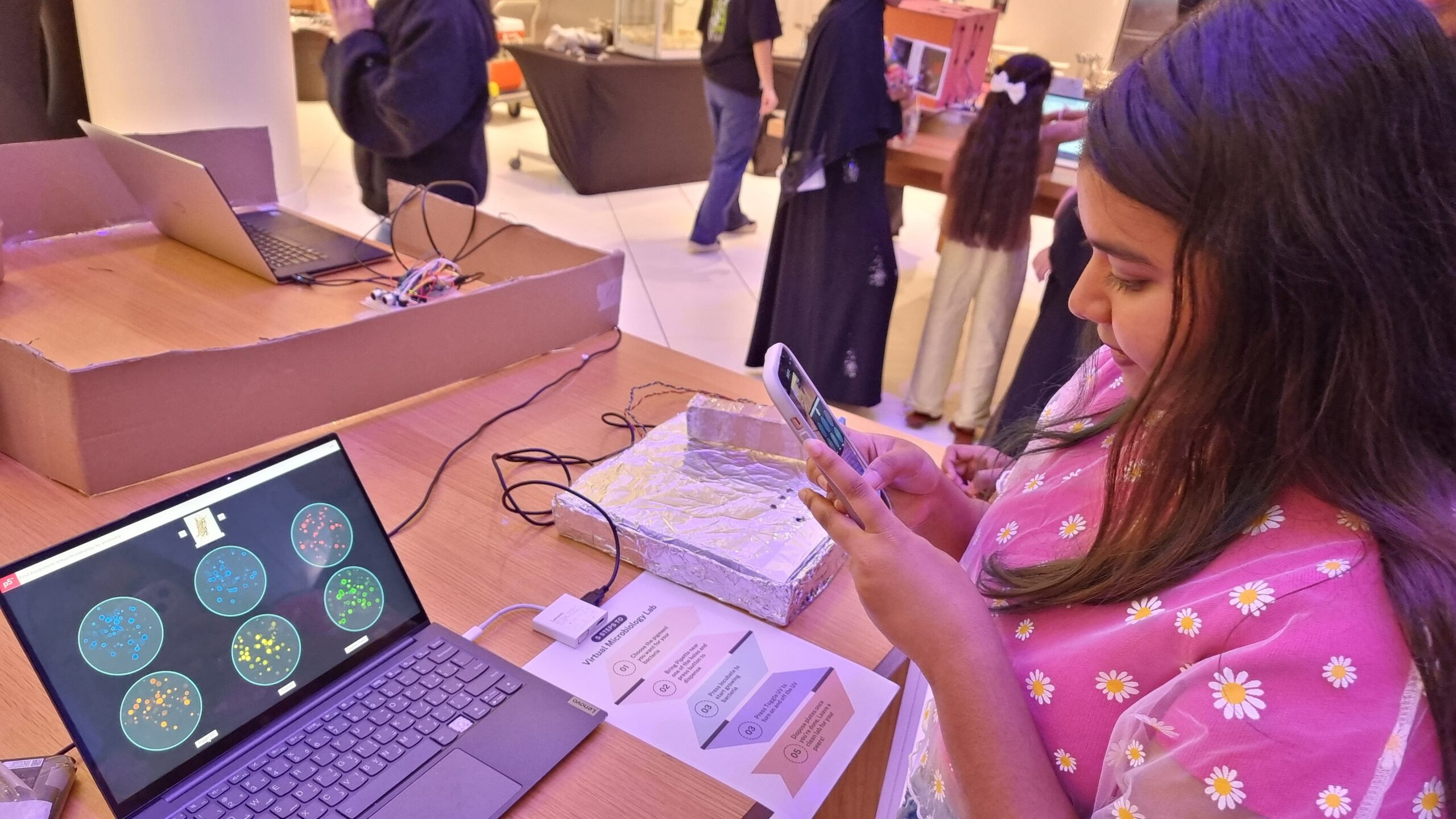
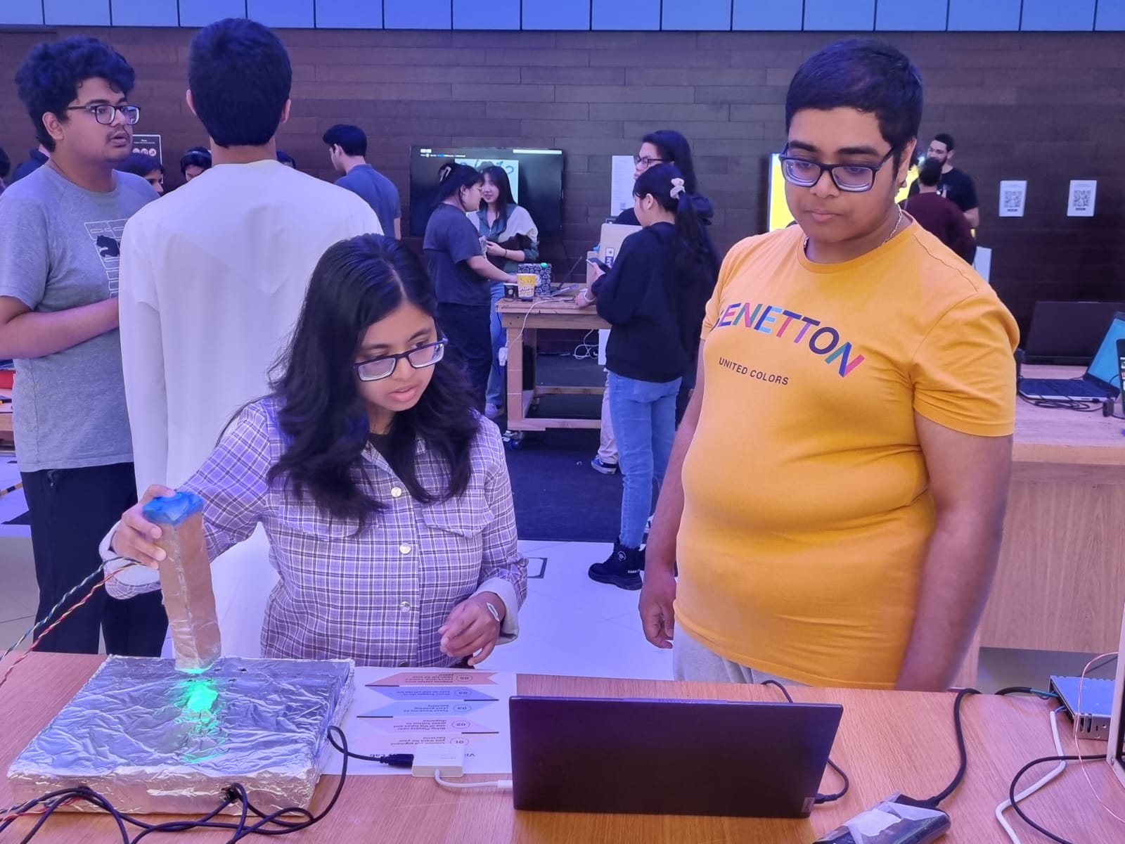
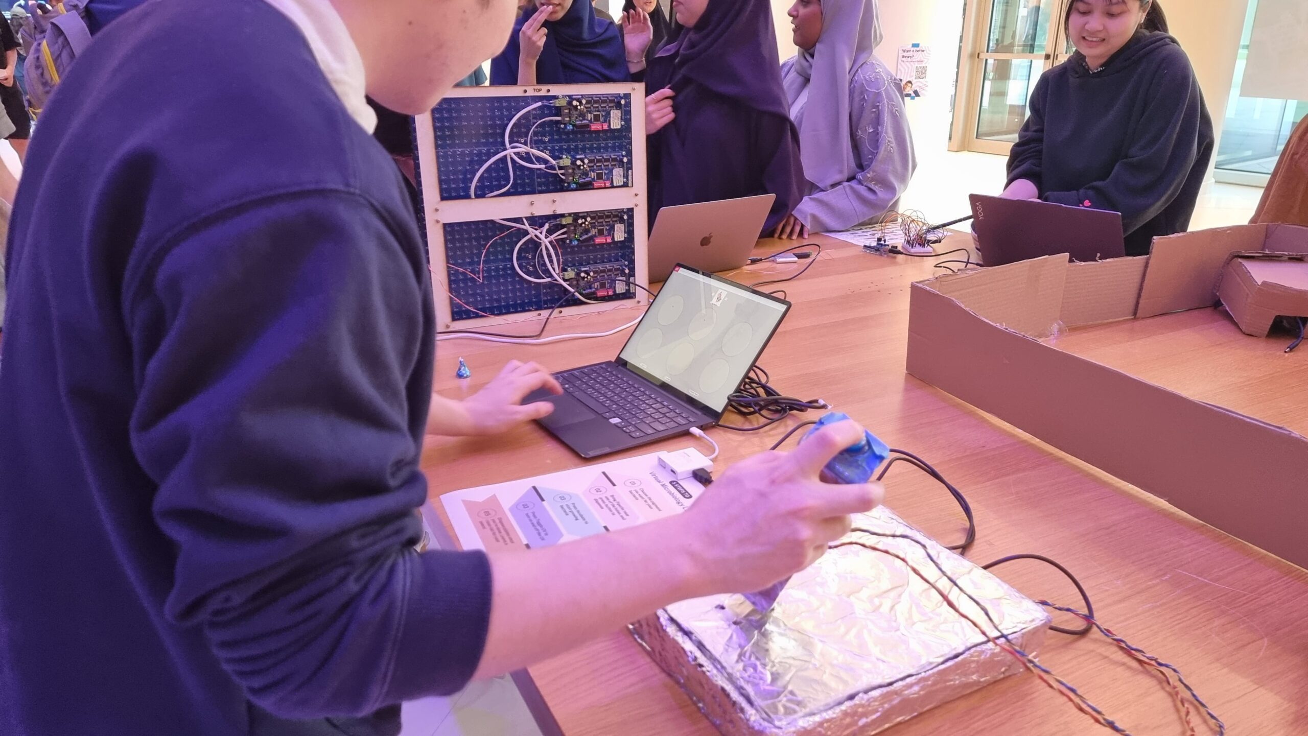
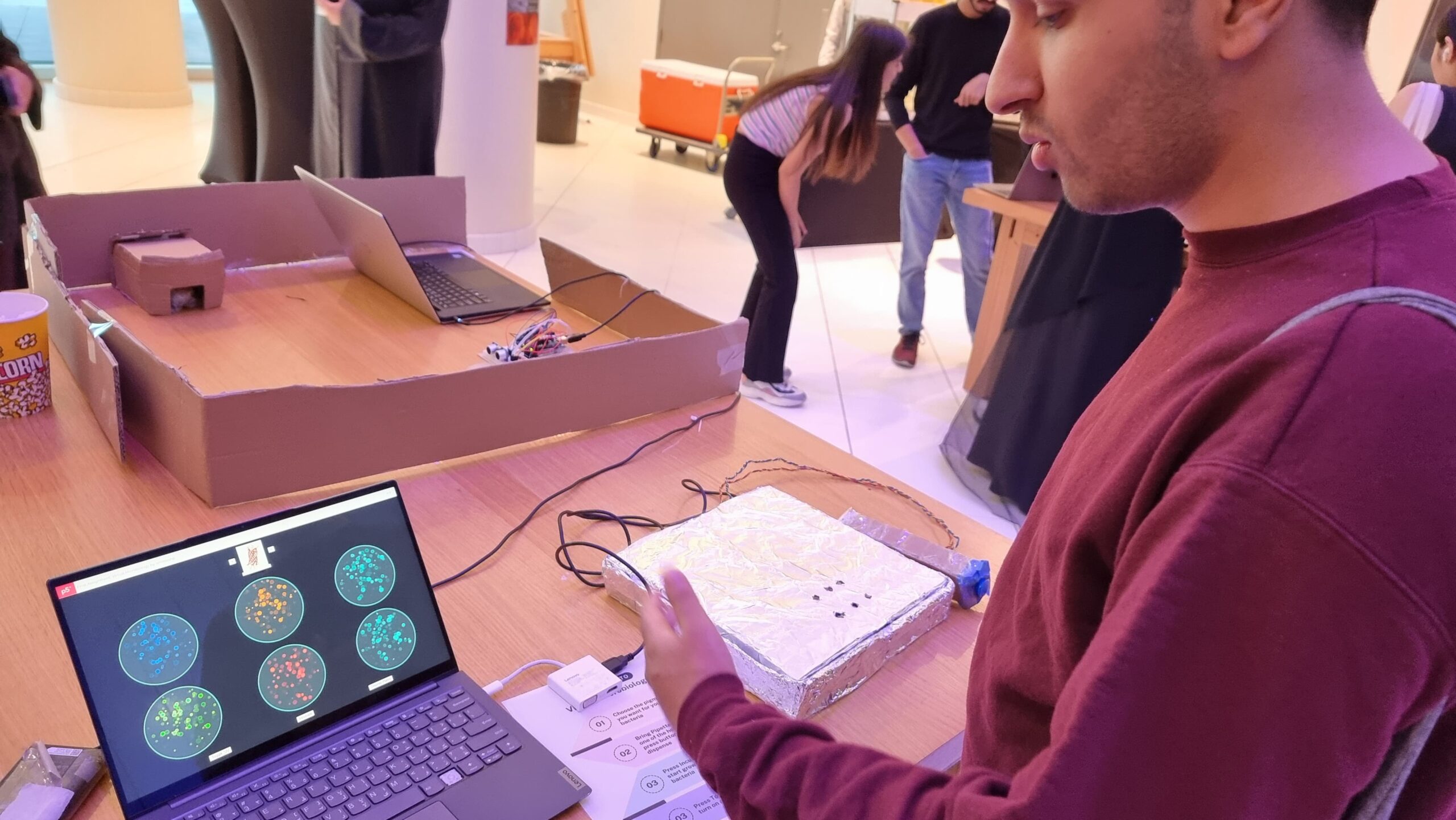
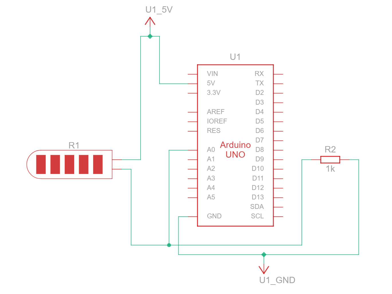
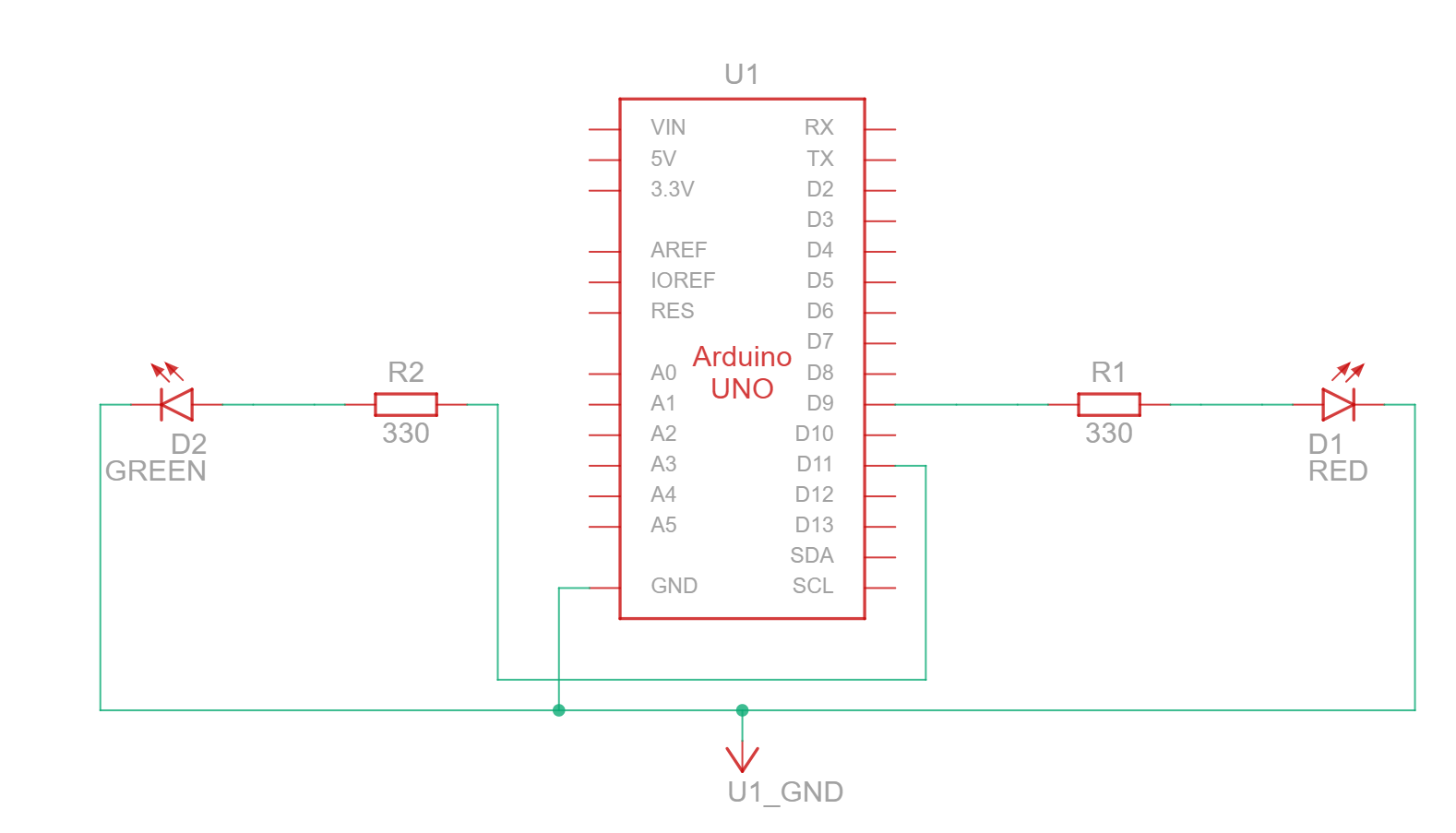
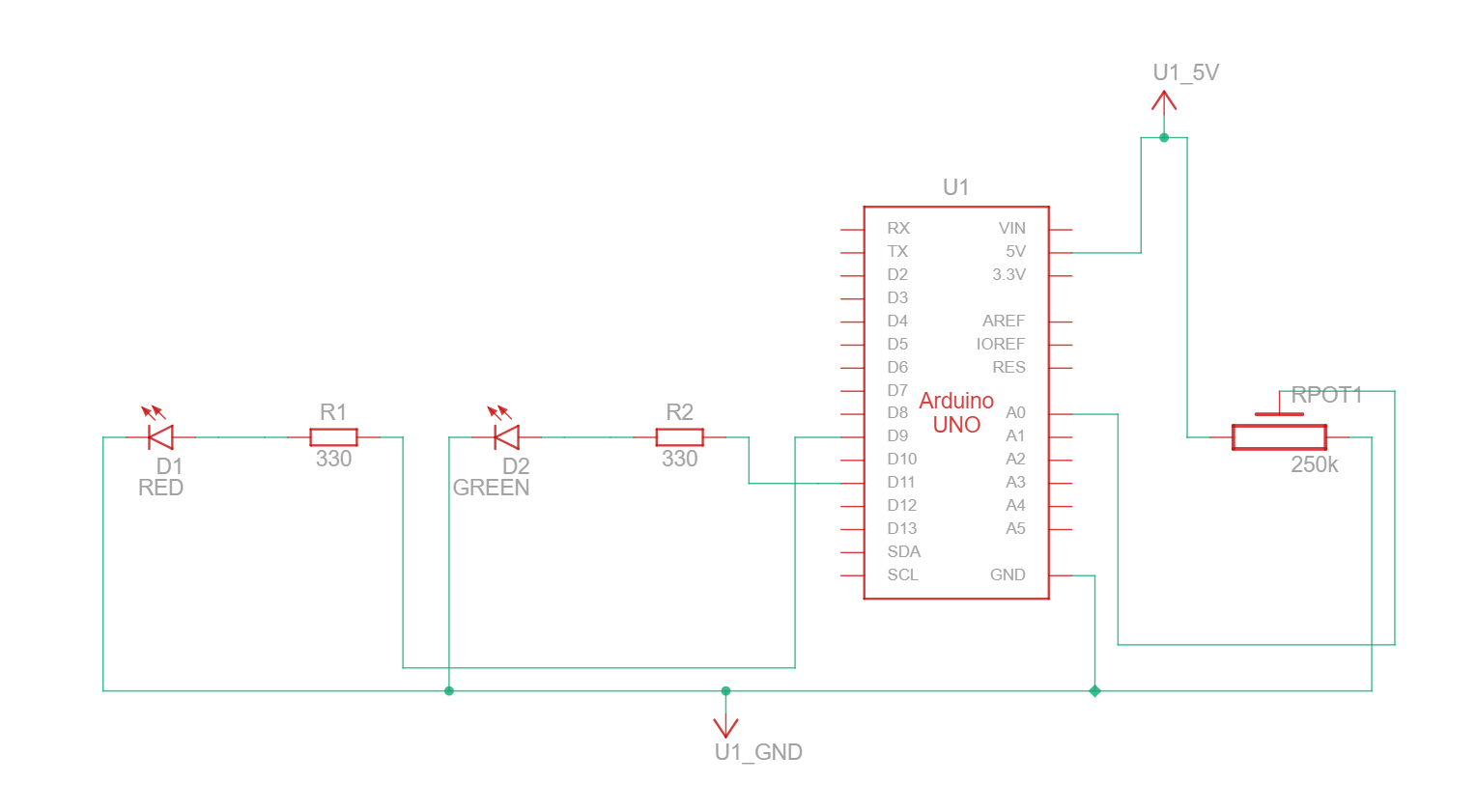


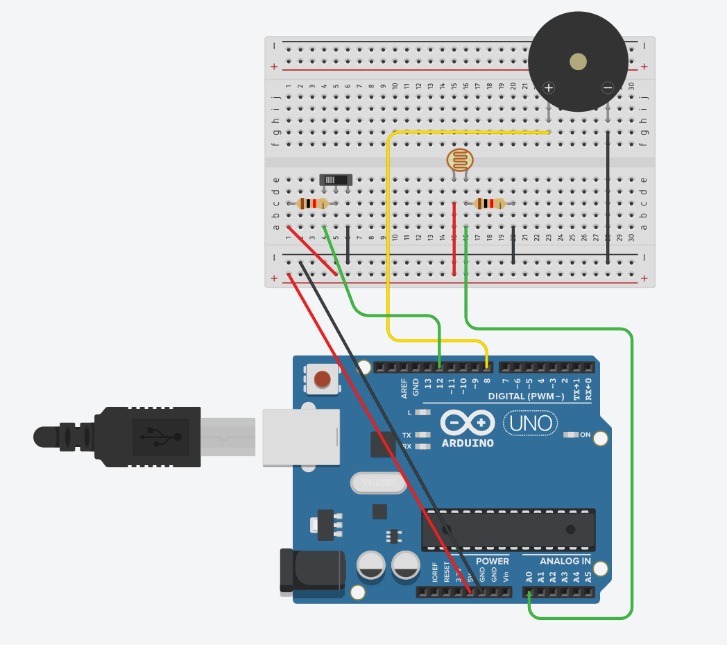
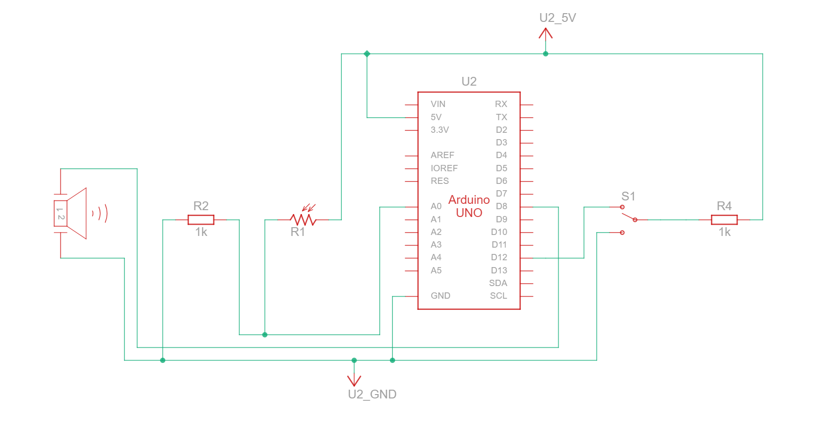
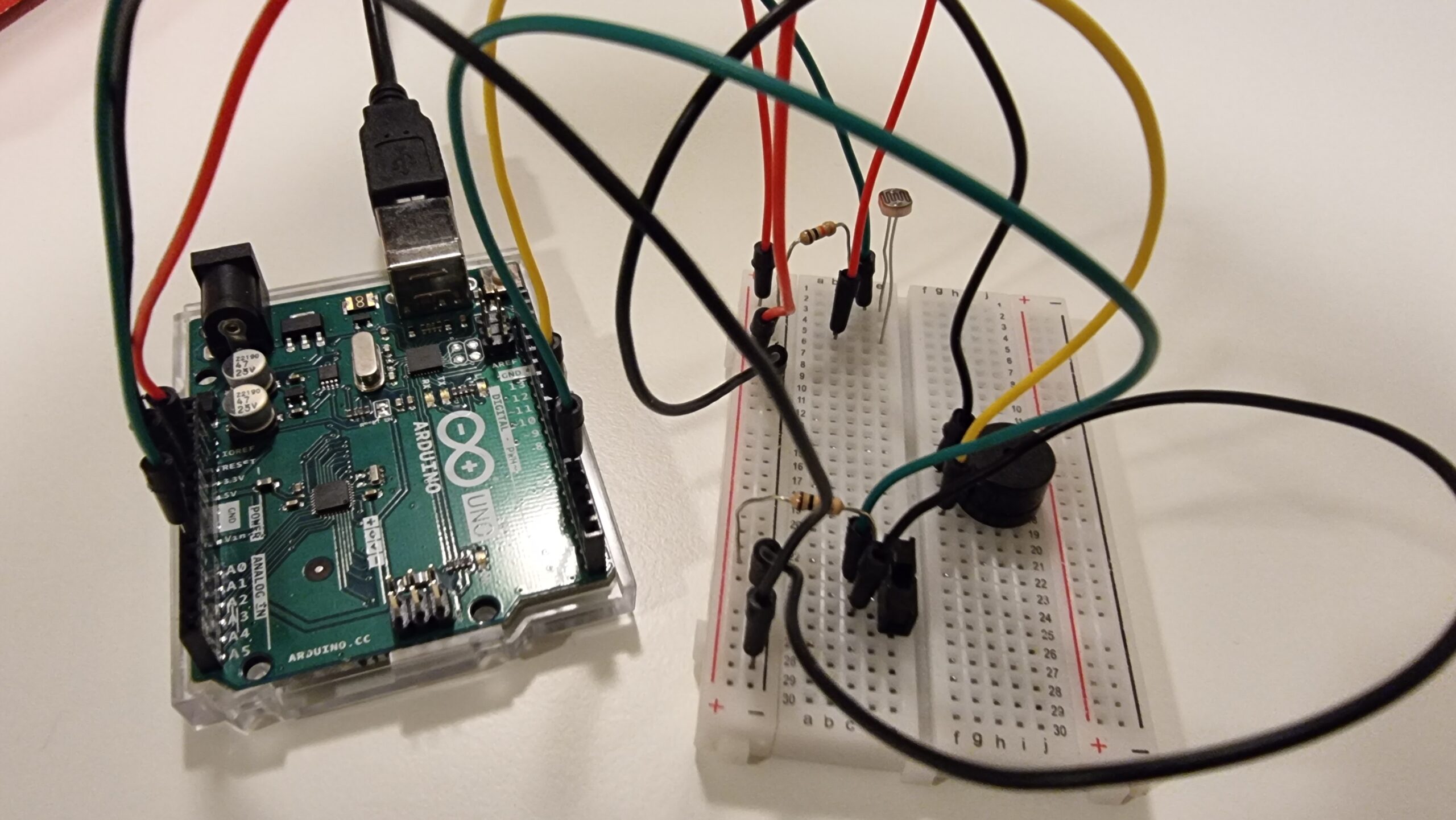
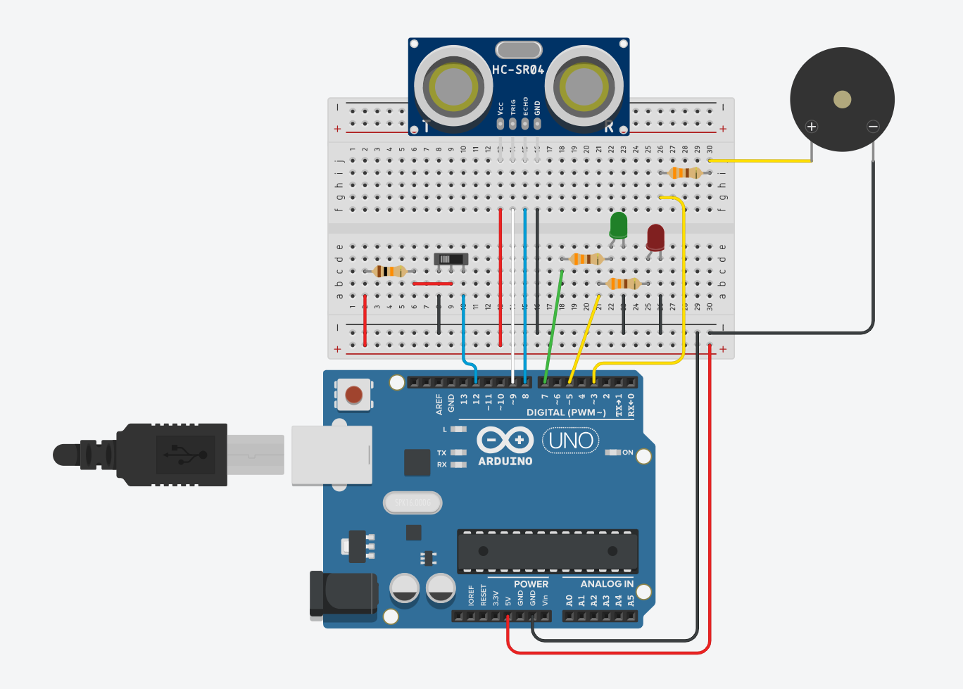 Figure 1: Component Simulation View
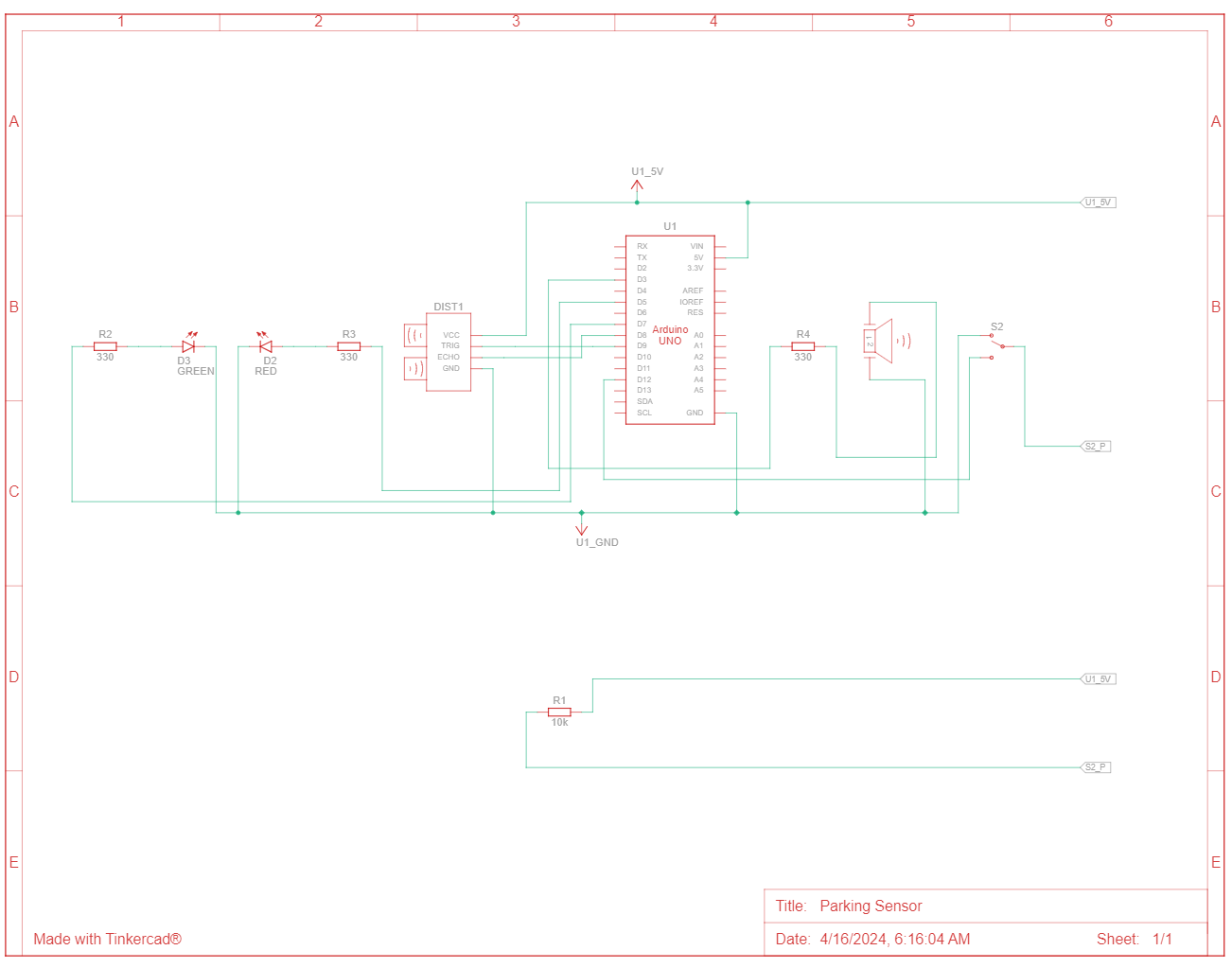 Figure 2: Schematic View
 Figure 3: Front View
 Figure 4: Top View
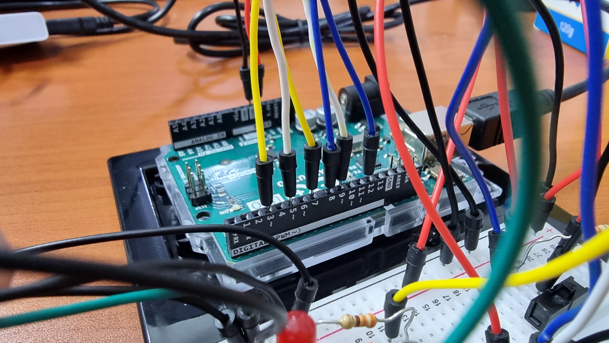 Figure 5: Arduino Pins Connection
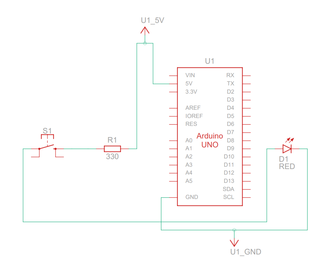 Figure 1: Circuit Diagram
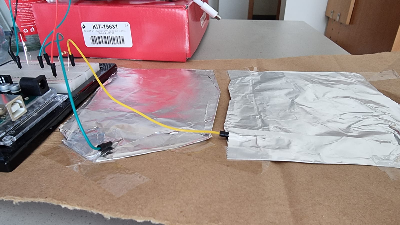 Figure 2: Switch terminals (the green terminal is +ve and the yellow terminal is -ve)