Week 12: Final Project Progress

Concept

Given the limited time constraint, the transforming robot presented a greater challenge, necessitating a reevaluation of the narrative and the concept as a whole.

At its core, the redesigned Project Utopia centers around an elegant yet challenging puzzle box. Each compartment represents a unique layer of interaction, requiring the user to solve riddles or manipulate physical components to unlock the next. Inside the compartments, users find carefully crafted informational cards and audio prompts that guide or enrich the experience.

Also, this redesign was inspired by the constraints of available technology, but it provided an opportunity to reimagine how interactive installations can connect with users through simplicity and creativity.

Features

At its heart, Project Utopia revolves around a puzzle box with multiple compartments. Each compartment contains riddles, cards with hidden clues, and audio prompts powered by p5.js. However, the twist lies in ARIS, the robotic overseer. As users engage with the puzzle box, ARIS intervenes—blocking, guiding, or assisting—depending on the challenge. This integration transforms the project into a blend of physical interaction, robotics, and storytelling, elevating the experience for participants.

The Box

A 3-d painted box, it has compartments which each secured with a unique mechanism, requiring users to solve challenges to access. The clearing of puzzles means that the person would be able to access the prompts and clues inside.

The Bot

The bot moves on two motored wheels with a castor wheel in the front for stability. It has one servo motor powered hand (made of cardboard), and

  • LCD Screen Eyes: Display emotions like suspicion, curiosity, or delight.
  • Servo Hand: Blocks premature access to the box.

it also is an expressive robot, meaning that major actions from the user will prompt expressions and sound from him.

The Code so far
#include <LiquidCrystal.h>
#include <Servo.h>

// Initialize LCDs
LiquidCrystal lcdLeft(2, 3, 4, 5, 6, 7);  
LiquidCrystal lcdRight(8, 9, 10, 11, 12, 13);

// Initialize the servos
Servo servoLeft;
Servo servoRight;

// Custom character arrays for expressions
byte happyEye[8] = {
  B00000,
  B01010,
  B00000,
  B10001,
  B01110,
  B00000,
  B00000,
  B00000
};

void setup() {
  // Begin LCDs
  lcdLeft.begin(16, 2);
  lcdRight.begin(16, 2);

  // Load custom characters
  lcdLeft.createChar(0, happyEye);
  // lcdLeft.createChar(1, confusedEye);

  lcdRight.createChar(0, happyEye);
  // lcdRight.createChar(1, confusedEye);

  // Start with a happy expression
  showHappyExpression();
}

void loop() {
  // Alternate expressions every 3 seconds
  showHappyExpression();
  delay(3000);
}

void showHappyExpression() {
  // Left Eye
  lcdLeft.clear();
  lcdLeft.setCursor(0, 0);
  lcdLeft.write(byte(0)); // Happy Eye

  // Right Eye
  lcdRight.clear();
  lcdRight.setCursor(0, 0);
  lcdRight.write(byte(0)); // Happy Eye
}

Week 11: Final Project Proposal

For my final project I decided to put the user experience and immersion as the main priority, while being eye-catching and unique.

So, my idea at the very basic level is the “Escape the Room” type. We have a transforming robot (and arduino one, and connected to p5.js) trapped in a big box, which has puzzles to solve. On the other hand, our main task is to help the robot, and interact with it. However, we have our own share of puzzles which can grant the robot inside something special (I would have to think this one through).

However, to make this one completely unique, I decided to form a story around it. The basic premise of the story is simple:

A.R.I.S. (Adaptive Recollection and Interface System) is a memory-keeping robot that gets stuck in a safe box’s shutdown room after being sabotaged. To restart A.R.I.S., the player has to answer both physical and digital tasks. The robot’s broken memories and changing personality show shocking facts about its past.

The player works with Arduino-powered machinery and p5.js-based digital tasks to find clues inside the box. These clues are the author of A.R.I.S.’s last-ditch attempts to protect secret information. The Utopia Protocol is a secret plan that these pieces point to. It could change the course of human history. But things get more dangerous when A.R.I.S. starts to doubt its mission and goes back and forth between being a friend and a possible threat.

At the end of the story, there is a moral choice, which I haven’t figured out just yet. However, based on some ways in which we have interacted with A.R.I.S means that the player can experience at least two endings.

Week 11: Reading Response

In this week’s reading, the idea for designers to prioritise aesthetics, cooperation, and diversity while developing assistive technologies struck a chord among the masses and have spread to a much wider scope. However, it has come with its own challenges of universality, fashion and so on.

A major core of the reading is focussed on designing for desire as long as utility is not comprimised. Hearing aids and prostheses have long been useful yet stigmatised owing to their utilitarian look. The author pushes for a more elegant design which devlops a sense of pride in its owner. Today, this wearable gadgets, for example, blur the barrier between function and fashion, with smartwatches serving as both style statements and health monitors. Similarly, minimalist gadgets like as folding keyboards and elegant standing workstations demonstrate how simplicity combined with beauty appeals to a wider audience.

Another good example is with prosthetic arms. One of the major reasons wearable prosthetic arms tend to be more expensive is because of the presence of quieter motors so that the wearer can not disturb the environment too much and draw attention to their impairment.

The theme of the reading, simply put, is that designers and users co-create products with the engineers (or people who figure out the science stuff). Once a radical idea, it is now standard in product development. His main argument that users should be active participants in shaping their tools finds echoes in today’s participatory design movements. Major brands regularly involve user feedback loops, whether through beta testing, user-generated content, surveys or iterative prototyping sessions.

That is why as engineers or Interactive Media students, we should think holistically about design – balancing aesthetics, accessibility, and functionality while keeping users at the center. This prevents long-term losses, maintains brand value, encourages innovation and open roads for other types of inventions.

Week 10: “Banana!!!!!”

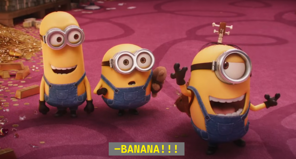
Yup, I was watching “Minions: Rise of Gru” over the weekend in order to find some inspiration for this week’s project, and I sure found the basis of my project when I watched this:

Concept

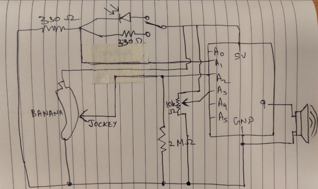
I decided on using a wheatstone bridge setup with two variable resistors (one photoresistor, and ‘the’ banana), and find the absolute difference between the two values and emit different sounds. I also decided to use a potentiometer to determine the pitch of the notes.

Apart from that, the user also has an option to not use the photoresistor at all by toggling the fixed 330 Ohm resistor in its place.

Material Required
  • Arduino Board
  • Jumper Wires
  • Breadboard
  • Potentiometer
  • 10k Ohm Resistors
  • 330 Ohm Resistors
  • SEN-09088 Photocell
  • Potentiometer
  • Banana
Schematic


Demonstration Video
Code

This Arduino code reads the voltage difference between V1 and V2, maps it to a frequency for the speaker, and uses a potentiometer to shift the octave.

// Pin configuration
const int v1Pin = A1;       // V1 of Wheatstone bridge
const int v2Pin = A2;       // V2 of Wheatstone bridge
const int potPin = A3;      // Potentiometer for octave control
const int speakerPin = 9;   // Speaker pin

// Variables for calibration and tuning
float baseFrequency = 220.0;  // Base frequency in Hz for a low A note
float maxVoltageDifference = 5.0;  // Maximum expected voltage difference (adjust as necessary)
int maxOctaveShift = 7;       // Maximum number of octaves to shift

void setup() {
  Serial.begin(9600);
  pinMode(v1Pin, INPUT);
  pinMode(v2Pin, INPUT);
  pinMode(potPin, INPUT);
  pinMode(speakerPin, OUTPUT);
}

void loop() {
  // Read voltage difference across V1 and V2
  float v1 = analogRead(v1Pin) * (5.0 / 1023.0);
  float v2 = analogRead(v2Pin) * (5.0 / 1023.0);
  float voltageDifference = abs(v1 - v2);

  // Map voltage difference to a frequency
  float noteFrequency = map(voltageDifference * 100, 0, maxVoltageDifference * 100, baseFrequency, baseFrequency * 2);

  // Read potentiometer and map to octave shift
  int potValue = analogRead(potPin);
  int octaveShift = map(potValue, 0, 1023, 0, maxOctaveShift);

  // Apply octave shift to the frequency
  noteFrequency *= pow(2, octaveShift);

  // Output the frequency to the speaker
  tone(speakerPin, noteFrequency);
  
  // Debugging output
  Serial.print("Voltage Difference: ");
  Serial.print(voltageDifference);
  Serial.print(" V, Frequency: ");
  Serial.print(noteFrequency);
  Serial.println(" Hz");

  delay(50);  // Delay for bouncing error
}
Conclusion and Reflection

Constructing this banana-powered musical instrument was a fun and an instructive process combining artistic design with technological principles. By using a Wheatstone bridge, I was quite free to play around on how I wanted to shape my music instrument.

Challenges Faced

1. Stabilizing the Output:
One major challenge was stabilizing the audio output, as random values were being read when the pencil jockey wasn’t in contact with the banana. This caused unwanted noises and a “wobbling” effect. To overcome this, I decided that I needed a pulldown resistor (here I used 2 Mega Ohms) to avoid reading noise in the Analog Pin A2

2. Mapping Voltage to Frequency Accurately:
Mapping the voltage difference to frequencies that sound musical took some experimentation. Adjusting the base frequency and range, as well as the octave shift, required fine-tuning to achieve the desired range of notes without distorting the sound.

Week 10: Reading Response

Bret Victor’s “A Brief Rant on the Future of Interaction Design” makes us think about how we describe and imagine “interaction.” Victor criticises the way we create interactions by saying that we should not limit them to finger swipes on touchscreens and instead use our hands and other senses.

He says that one of the main problems with the business is that it only cares about “pictures under glass,” while touchscreens are now used for everything. He says that this method doesn’t use the full ability of human hands, which can do a lot more than just swipe or tap. This made me think: How often have I just used touchscreens or buttons as “interactive” features without thinking about how they use or more importantly limit our physical abilities?

This interpretation also begs a crucial question: “How much have we actually improved the ways in which the ‘interactive system’ gives us feedback when we interact with something?” Actually, we are not even near enough to create a significant kind of interactive system. This is so because we neglected haptic feedback. Our hands are a collection of many kinds of sensors: heat, pressure, force, electrical, and so on. Although Victor’s perfect is employing hands in a whole spectrum of natural movements, I think haptic feedback may help to design interaction going forward.

Finding the substitutes for actual haptic input interests me as an engineering student. To replicate physical input, I may use motor vibrations, tension-based devices, or even resistance-based sensors. That is why in my creative switch project, I used a pulley mechanism to lift the connecting switch, which is to invite the user into engaging in an interactive physical system and is able to feel a sense of ‘weight’.

Week 8: Unusual Switch: The Gravity Switch

Concept

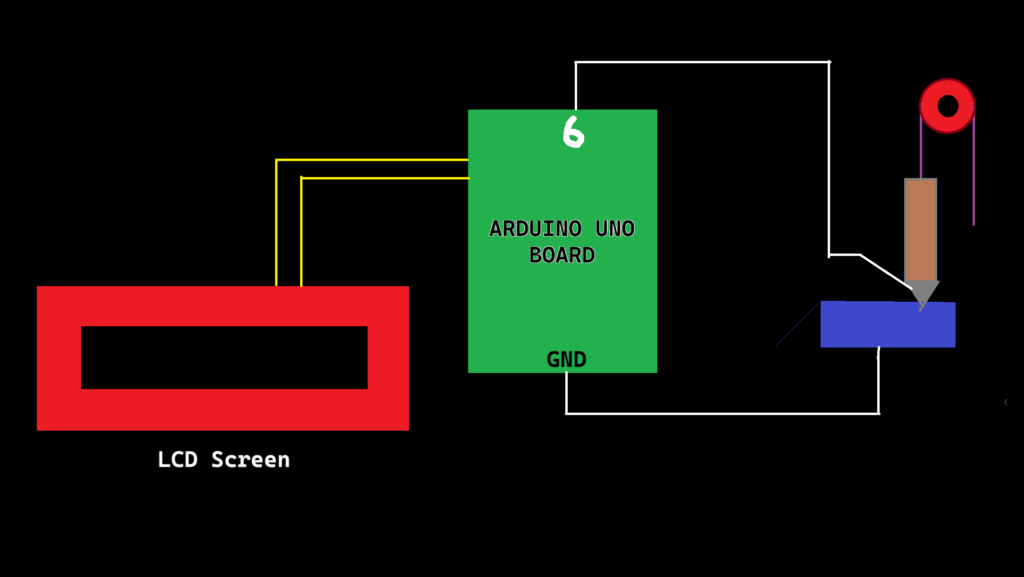
This assignment is the most unique one as at the most basic level, we had to utilize the physical systems around us to make or break a circuit. That’s why I decided to use an everyday tool- the pulley to control the flow of electricity. Rather than pressing a button or flipping a switch, the user plays a more active role in balancing forces. The switch itself is a rotating beam with a conducting end, which is lifted or dropped through a pulley mechanism onto a conductive plate. By carefully adding or removing weights, the user must balance or offset gravity to either make or break the connection. A simple two dimensional diagram of the same looks like this:


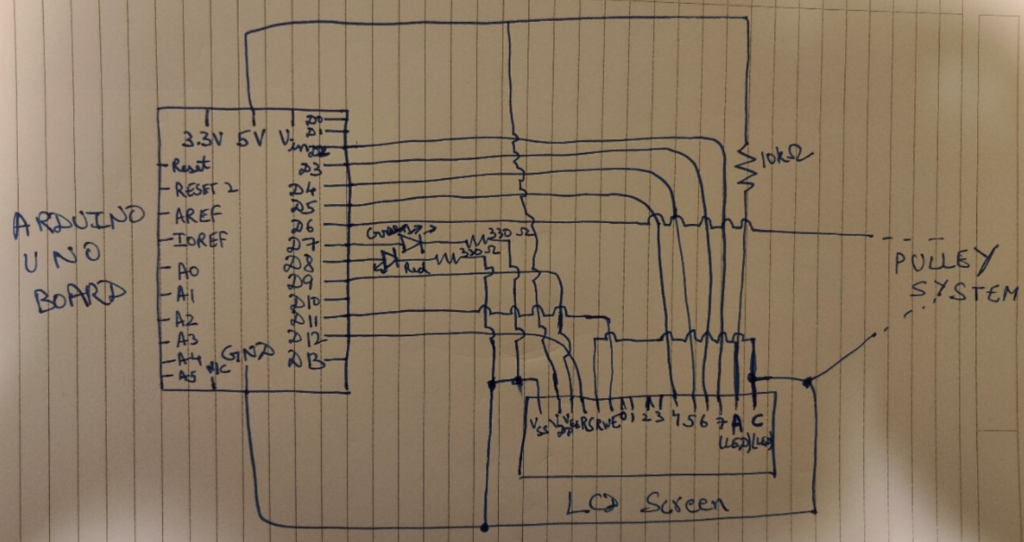
And the circuit schematic is:

Circuit Schematic

The Physics behind it

When the weight of the external weights added create enough torque to lift the heavy end of the beam, the lighter end of the beam (the one having the conducting pin), moves down to touch the conducting plate, completing the circuit and prompting the “LOW” state (because of the Pullup Input).

This state is pivotal, as it is needed to switch which LED lights up in the Arduino. Simply put, we use the red LED for stopping the user to add weight in the pan (which is associated to the “HIGH” state of the switch) and green LED to continue adding the weights (which is associated to the “LOW” state of the switch).

Thus, the Gravity Switch, which uses a Simple Pulley mechanism, Physics and Arduino actualy behaves as a “Toggle Switch,” but we don’t user our hands in a direct way. We simply rely on Gravity to do the connecting part for us.

Code Implementation

The only library imported was the LCD Library “Liquid Crystal.h”.

Now, according to the code:

// Including the required libraries
# include <LiquidCrystal.h>

// Initialize the library with the numbers of the interface pins
LiquidCrystal lcd(12, 11, 5, 4, 3, 2);
const int contrast = 90;
const int contrastPin = 9;

// Defining the Global Variables
// Defining the LED pins
const int redLEDPin = 8;     // Pin used for reading the state of the switch of Red LED
const int greenLEDPin = 7;   // Pin used for reading the state of the switch of Green LED

// Defining the switch pin 
const int switchPin = 6;     // Pin used for reading the switch state to decide which LED lights up
int switchState;
int previousSwitchState = -1;

// Setup Function
void setup() {
  // Setting the Pin to Input to read its state
  pinMode(redLEDPin, OUTPUT);
  pinMode(greenLEDPin, OUTPUT);
  pinMode(switchPin, INPUT_PULLUP);

  // Initialize the LCD and set up the columns and rows
  lcd.begin(16, 2);
  delay(500);

  // Setting up the contrast for LCD Display as not using Potentiommeter
  analogWrite(contrastPin, contrast);
  Serial.begin(9600);
}

// Loop Function
void loop() {
  switchState = digitalRead(switchPin);

  // Only clear and update the LCD when the switch state changes
  if (switchState != previousSwitchState) {
    lcd.clear();  // Clear the screen only when the state changes

    if (switchState == LOW) {
      lcd.setCursor(0, 0);
      lcd.print("Switch is ON.");
      lcd.setCursor(0, 1);
      lcd.print("Add more weight!");

      Serial.println("SWITCH STATE IS HIGH ");
      digitalWrite(greenLEDPin, HIGH);
      digitalWrite(redLEDPin, LOW);
    }
    
    else {
      lcd.setCursor(0, 0);
      lcd.print("Switch is OFF.");
      lcd.setCursor(0, 1);
      lcd.print("HALT THE WEIGHTS");

      Serial.println("SWITCH STATE IS LOW");
      digitalWrite(redLEDPin, HIGH);
      digitalWrite(greenLEDPin, LOW);
    }

    previousSwitchState = switchState;  // Update the previous state
  }

  delay(100);
}

In the code, I have used the pins 2, 3, 4, 5, 11 and 12 for the D4, D5, D6, D7, Enable, and RS pin on the LCD Display. I have used a fixed 10k Ohm resistor instead of the potentiometer for the contrast level (As we don’t want to use our hands directly in any part of the project).

Also, Pin 6 is the main switch pin which is responsible for reading the state, and the entire circuit (+ LCD) behaves according to the state.

Head Scracthing Software Problems faced

In communicating with the LCD Screen, some problems were faced, notably the random toggling of the switch input when it was not connected. This was caused by a floating input pin – a common issue in digital electronics. A floating pin picks up electrical noise, resulting in irregular behavior. The solution involved enabling the internal pull-up resistor using “INPUT_PULLUP” on the switch pin. This ensures that the switch pin has a default state of HIGH when not pressed, making the input stable and reliable. (I got to know about this from the Arduino Forum: https://forum.arduino.cc/t/arduino-input-seems-to-be-randomly-toggling/448151)

Another issue was the LCD displaying random characters in a flow instead of the expected text. This issue had multiple causes: frequent clearing of the display, incorrect contrast settings, and potential timing issues during initialization. The frequent use of lcd.clear() in every loop iteration was causing the screen to flicker and show inconsistent outputs. By refactoring the code to only clear the LCD when the switch state changed, the display became stable and only updated when necessary, improving both performance and readability.

Demonstration Video

Problems associated

  • If the user puts too weight, the beam or the conducting pin can bend or break, which will make the circuit useless.
  • One can also lift the beam by themselves to make the pin touch the conducting plate, but that defeats the purpose of the assignment.
  • I also wanted a smaller more heavier block which has the Pin 6 installed as the main weight, but the closest I could get was that block in the demonstration video.
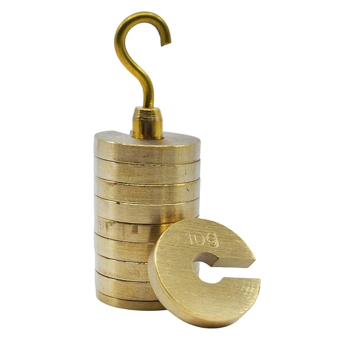
  • I wanted to use the Slot weights like these:

which are typically used in Physics experiments (but I could not find them anywhere *sad noises*)

Week 9: Reading Response

Both of this week’s readings explore the common creative challenges and themes in Design and Interactive Media.

Physical Computing’s Greatest Hits (and Misses)

The reading was nostalgic for me as it recounted several projects which I used to do in my school days for exploring the world of electronics. However, these projects are the starting point for many electronic-based fields and have withstood the test of time like Interactive Gloves, LED based projects, Video Mirrors, and so on. The author emphasizes on the fact that these projects are building blocks for other interactive projects and many famous digital works of art are variations of these seemingly simple projects. However, despite their simplicity, by changing one factor or adding another component, the entire project becomes something new. Thus, these ideas might not seem “original”, but can be interpreted in an entirely different manner it takes inspiration from.

What strikes me most in this reading is the challenge of achieving a balance between visual appeal and meaningful interaction. For example, video mirrors are essentially screens that mimic the viewer’s movements and they are captivating to look at, but limited in what they offer interactively. The author raises an important point here: while these types of projects are beautiful, they don’t necessarily provide much depth in interaction. I agree with him because I have experienced the same with my Midterm Project- it was beautiful, but offered limited interaction. I was wound up in the making the project work that I did not think of the project from a user’s perspective.

Another theme that emerges is the idea of adaptability. The author encourages creators to see these “tried – and – true” themes not as stale, but as playgrounds for innovation. This idea of keeping traditional themes fresh is something that really resonates with me. How do we, as creators, continue to reinvent these classics in a way that speaks to new audiences? That is a question which I believe everyone would answer in their own way. For me, I use some basic physics principles with electronics to bring my own twist into my projects.

Making Interactive Art: Set the Stage, Shut Up and Listen

This reading really brings a fresh perspective on an artist’s role. The author challenges creators to move away from interpreting their work or instructing audiences on what to think. Instead, he sees interactive art as a conversation that begins with the artist but is completed by his audience. This concept reminds me of theater, where the director sets the scene but leaves it to the actors to interpret their roles (to allow some freedom in exploring that character). In this case, it’s the audience that gets to step into the role of interpreter, finding their own meaning in the art.

One of the most intriguing aspects of this reading is the emphasis on “letting go of control.” For many artists, this can be challenging because we are often taught that art is an act of personal expression, a statement that’s “ours.” But interactive art, according to the author, flips that on its head – it’s no longer just our statement; it’s a shared experience. The author argues that our job is to give subtle hints, to design a space that encourages discovery, and then to get out of the way. This idea resonates with me because it’s about trusting the audience to bring their own insights and emotions to the work. This encourages me to use subtle hints rather than hard-coded instructions to engage the audience with my work.


Week 8: Don Norman and Margaret Hamilton Reading

Both of this week’s readings are the result of developing a complex relationship between aesthetics, degree of complexity and function. Norman in his readings states that inproving the user experience through design is important as it allows users to ignore the minor flaws and bugs by impressing them with creativity. For example, he states that walking the plank at different heights might seem same, but as the height increases, a person might reconsider that. However, if there are some aesthetic design incorporation, then one might choose to do so either due to aesthetic curiosity. However, initially going through Margaret Hamilton’s reading, even I was quite sure that her view is quite in contrast with Norman, as she focusses majorly on error-free, mission-critical functionality while designing software for the Apollo systems. This is because of the risks involved in her work. At the moon surface, a place unknown to humans, anything could go wrong and total preparation was needed. This became clear when just before landing on the moon, the computer overwhelmed with the many tasks on hand, chose to prioritize the main task, and leave the others.

However, Norman’s approach to adaptability in design based on aesthetics goes well with Hamilton’s approach to adaptability in systems. Norman thinks that an appealing interface makes a product more usable for a wider range of people. Hamilton, on the other hand, worked with NASA on the Apollo program and showed adaptability through strict, modular engineering that could handle unexpected edge cases, like when her daughter made a critical error during testing. These similar and different ideas show that Norman’s ideas about beauty make everyday things easier to use, while Hamilton’s high-stakes setting shows how important it is to build for reliability and test things thoroughly, which is an important quality in and of itself for life-or-death tasks.

Midterm Project: The “SpectroLoom”

Concept

For my midterm project, I thought of making something unique, which seemed like art for the casual viewers, but on closer inspection would be seen as a form of data. For this, I decided to make a circular spectrogram, i.e, visualizing sound in circular patterns. That’s when I saw an artwork on Vimeo, which visualized sound in a unique way:

Using FFT analysis, and the concept of rotating layers, I decided to recreate this artwork in my own style, and go beyond this artwork, thus, creating the SpectroLoom. I also decided that since most people sing along or hum to their favourite tunes, why not include them in the loop too?

At its core, SpectroLoom offers two distinct modes: “Eye of the Sound” and “Black Hole and the Star.” The former focuses solely on the auditory journey, presenting a circular spectrogram that spins and morphs in harmony with the music. The latter introduces a dual-layered experience, allowing users to sing along via microphone input, effectively merging their voice with the pre-loaded tracks, thus creating a sense of closeness with the song.

The Code/Science

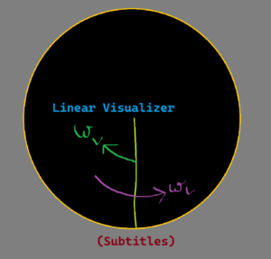
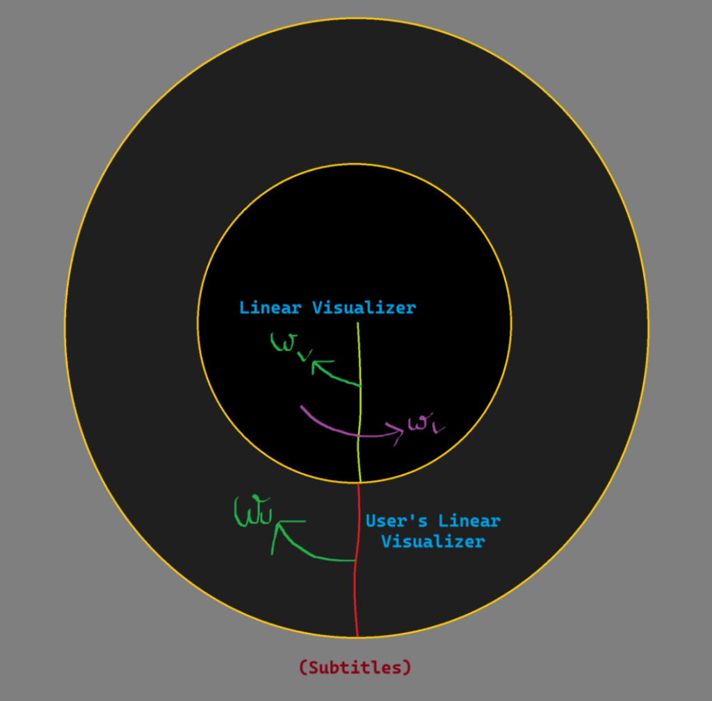
Apart from FFT analysis, the project surprisingly used a lot of concepts related to “Relative Angular Velocity”, so that I could make the sketch behave in the way I want it to be. Using FFT analysis, I was able to get the amplitude of every frequency at any given point of time. I used these values to make a linear visualizer on a layer. The background canvas is rotating at an angular velocity of one revolution for the song’s duration in anti-clockwise direction, and the visualizing layer is rotating in the opposite direction (clockwise), making it seem that the linear visualizer is stationary because the Relative Angular Velocity is “Zero”. The other user layer, which have the user’s waveform is also doing the same, but uses the mic input as the input source for the FFT Analysis (and is only in the second mode).

Also, once the user finishes the song, they can again left click for restarting the same music. This is done by resetting the angle rotated by the layer to “Zero” after a complete revolution and clearing both song visualization layer and the User input layer.

// Visualizer screen drawing function for "Black Hole and the Star" mode
function drawBlackHoleAndStar() {
  if (song.isPlaying()) {
    background(0);

    // Get the frequency spectrum for the song
    let spectrumA = fft.analyze();
    let spectrumB = spectrumA.slice().reverse();
    spectrumB.splice(0, 40);

    blendAmount += colorBlendSpeed;
    if (blendAmount >= 1) {
      currentColor = targetColor;
      targetColor = color(random(255), random(255), random(255));
      blendAmount = 0;
    }

    let blendedColor = lerpColor(currentColor, targetColor, blendAmount);

    // Draw song visualizer
    push();
    translate(windowWidth / 2, windowHeight / 2);
    noFill();
    stroke(blendedColor);
    beginShape();
    for (let i = 0; i < spectrumB.length; i++) {
      let amp = spectrumB[i];
      let x = map(amp, 0, 256, -2, 2);
      let y = map(i, 0, spectrumB.length, 30, 215);
      vertex(x, y);
    }
    endShape();
    pop();

    layer.push();
    layer.translate(windowWidth / 2, windowHeight / 2);
    layer.rotate(radians(-currentAngle));
    layer.noFill();
    layer.colorMode(RGB);

    for (let i = 0; i < spectrumB.length; i++) {
      let amp = spectrumB[i];
      layer.strokeWeight(0.02 * amp);
      layer.stroke(amp, amp, 255 - amp, amp / 40);
      layer.line(0, i, 0, i);
    }
    layer.pop();
    
    var userSpectrum = micFFT.analyze()

    userLayer.push();
    userLayer.translate(windowWidth / 2, windowHeight / 2);
    userLayer.rotate(radians(-currentAngle));
    userLayer.noFill();
    userLayer.colorMode(RGB);

    for (let i = 0; i < userSpectrum.length; i++) {
      let amp = userSpectrum[i];
      userLayer.strokeWeight(0.02 * amp);
      userLayer.stroke(255 - amp, 100, 138, amp / 40);
      userLayer.line(0, i + 250, 0, i + 250); // Place the user imprint after the song imprint
    }

    userLayer.pop();

    push();
    translate(windowWidth / 2, windowHeight / 2);
    rotate(radians(currentAngle));
    imageMode(CENTER);
    image(layer, 0, 0);
    image(userLayer, 0, 0);
    pop();
  
    currentAngle += angularVelocity * deltaTime / 1000;

    if (currentAngle >= 360) {
      currentAngle = 0;
      
      userLayer.clear();
      layer.clear();
    }

    let level = amplitude.getLevel();
    createSparkles(level);

    drawSparkles();
  }
}

Also, there is the functionality for the user to restart too. The functionality was added via the back function. This brings the user back to the instruction screen.

function setup(){
...
  // Create back button
  backButton = createButton('Back');
  backButton.position(10, 10);
  backButton.mousePressed(goBackToInstruction);
  backButton.hide(); // Hide the button initially
...
}

// Function to handle returning to the instruction screen
function goBackToInstruction() {
  // Stop the song if it's playing
  if (song.isPlaying()) {
    song.stop();
  }
  
  // Reset the song to the beginning
  song.stop();
  
  // Clear all layers
  layer.clear();
  userLayer.clear();

  // Reset mode to instruction
  mode = "instruction";
  countdown = 4; // Reset countdown
  countdownStarted = false;

  // Show Go button again
  goButton.show();
  blackHoleButton.show();
  songSelect.show();
}

The user also has the option to save the imprint of their song via the “Save Canvas” button.

// Save canvas action
function saveCanvasAction() {
  if (mode === "visualizer") {
    saveCanvas('rotating_visualizer', 'png');    
  }
  if (mode === "blackhole") {
    saveCanvas('user_rotating_visualizer', 'png')
  }
}

Sketch

Full Screen Link: https://editor.p5js.org/adit_chopra_18/full/v5S-7c7sj

Problems Faced

Synchronizing Audio with Visualization:
    • Challenge: Ensuring that the visual elements accurately and responsively mirror the nuances of the audio was paramount. Variations in song durations and frequencies posed synchronization issues, especially when dynamically loading different tracks.
    • Solution: Implementing a flexible angular velocity calculation based on the song’s duration helped maintain synchronization. However, achieving perfect alignment across all tracks remains an area for refinement, potentially through more sophisticated time-frequency analysis techniques.
Handling Multiple Layers and Performance:
      • Challenge: Managing multiple graphics layers (layer, userLayer, tempLayer, etc.) while maintaining optimal performance was intricate. Rendering complex visualizations alongside real-time audio analysis strained computational resources, leading to potential lag or frame drops.
      • Solution: Optimizing the rendering pipeline by minimizing unnecessary redraws and leveraging efficient data structures can enhance performance. Additionally, exploring GPU acceleration or WebGL-based rendering might offer smoother visualizations.
Responsive Resizing with Layer Preservation:
    • Challenge: Preserving the state and content of various layers during window resizing was complex. Ensuring that visual elements scaled proportionally without distortion required meticulous calculations and adjustments.
    • Solution: The current approach of copying and scaling layers using temporary buffers serves as a workaround. However, implementing vector-based graphics or adaptive scaling algorithms could provide more seamless and distortion-free resizing.

Midterm Project Progress: Eye of the Sound

Concept

The “Eye of the Sound” is a project which transforms sound into mesmerizing visual art using the principles of physics. There are many others before me who have used music as a way of generating artwork, like:

However, there was one artwork which was quite interesting to see on Vimeo: A circular spectrogrram. This project would be based on this visualization at the core and would be expanded on that too.

This spectrogram appears to be mostly based on the loudness of the sound, and though it is an intriguing and cool artwork, has no user interaction, no generative features, and so on. That’s where my project, “Eye of the sound” comes in. It would be based on sensory experiences of sound and sight, and the circular flow is inspired from the flow of life, and the end is quite similar to the ‘Iris’ of the eye, a symbol of life.

Implementation

I have a basic idea of what must be done in the project. The central part of the project would be FFT (Fast Fourier Transform Analysis) to distinguish the different frequencies in the song, and then use a linear visualizer to display it. The visualizer’s displacement from the mean position is stored in an array, and is used to display the results on a rotating graphics buffer layer. The layer is rotating in one direction, and the visualizer in the opposite direction to cancel the rotation effect and “appear” stationary.

The color of the imprints on the layer are based on the loudness, and the intensity of the imprints is determined by the FFT analysis. The subtitles are displayed below.

The user also has another option in which they are able to sing along with the music being played, and their voice imprints are also calculated and diplayed in the same manner but in a different color scheme according to them.

This means that providing a menu screen for the user in which the instructions are provided and separate buttons are there to lead them to the mode they want.

Improvements which can be made

  • Adding a choosing the song screen, where the user can select some songs from some options in both the modes
  • Adding a sprite running loading bar for the amount of song left
  • Adding some generative effects on the subtitles, or some sparkle effects on the “highs” of a song
  • Adding a performance score in the second mode to see how well the user has done with the song
  • A “Save Canvas” option for the user to store their experiences.