Final Project – Walking Buddy

CONCEPT:

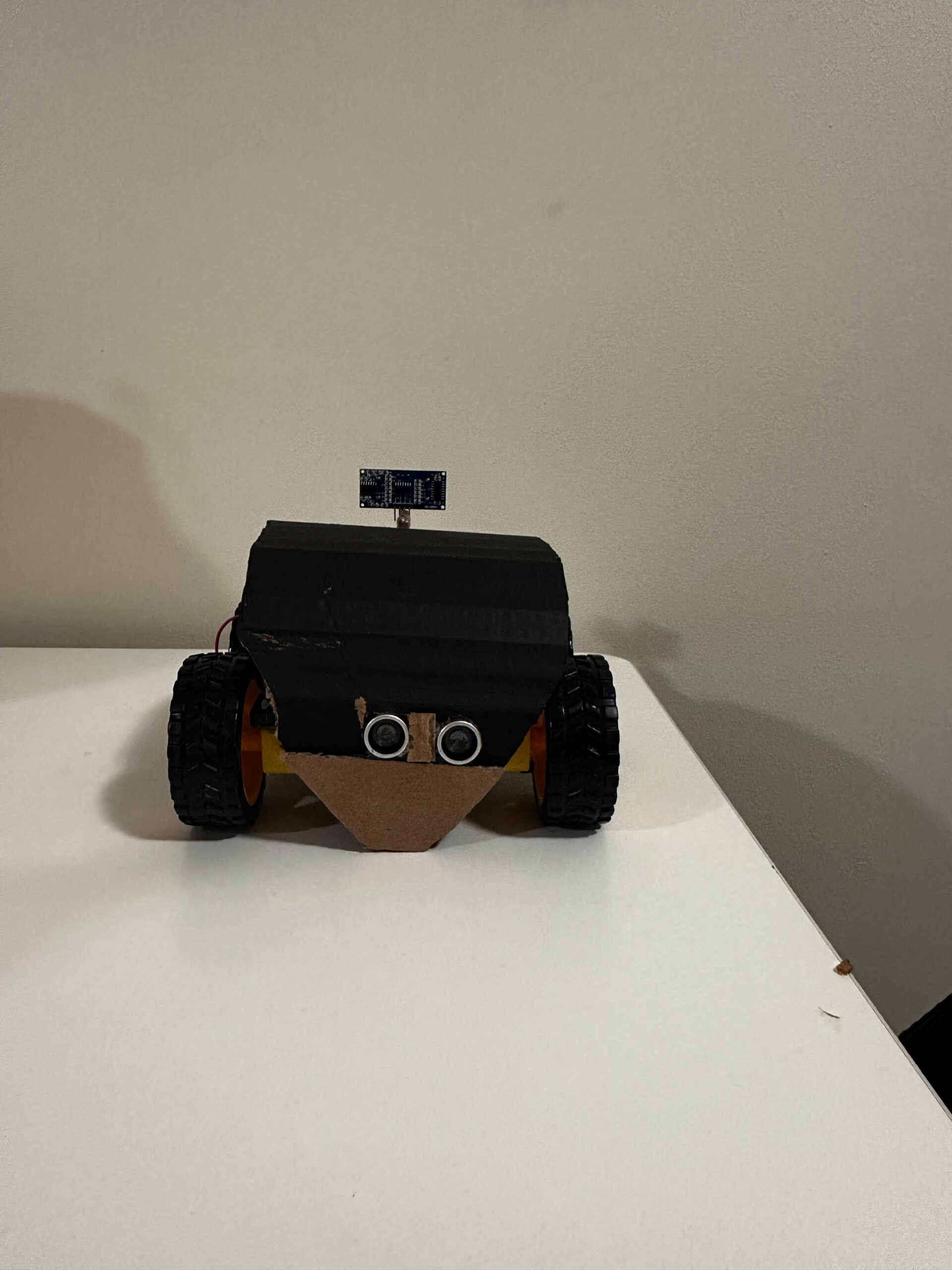
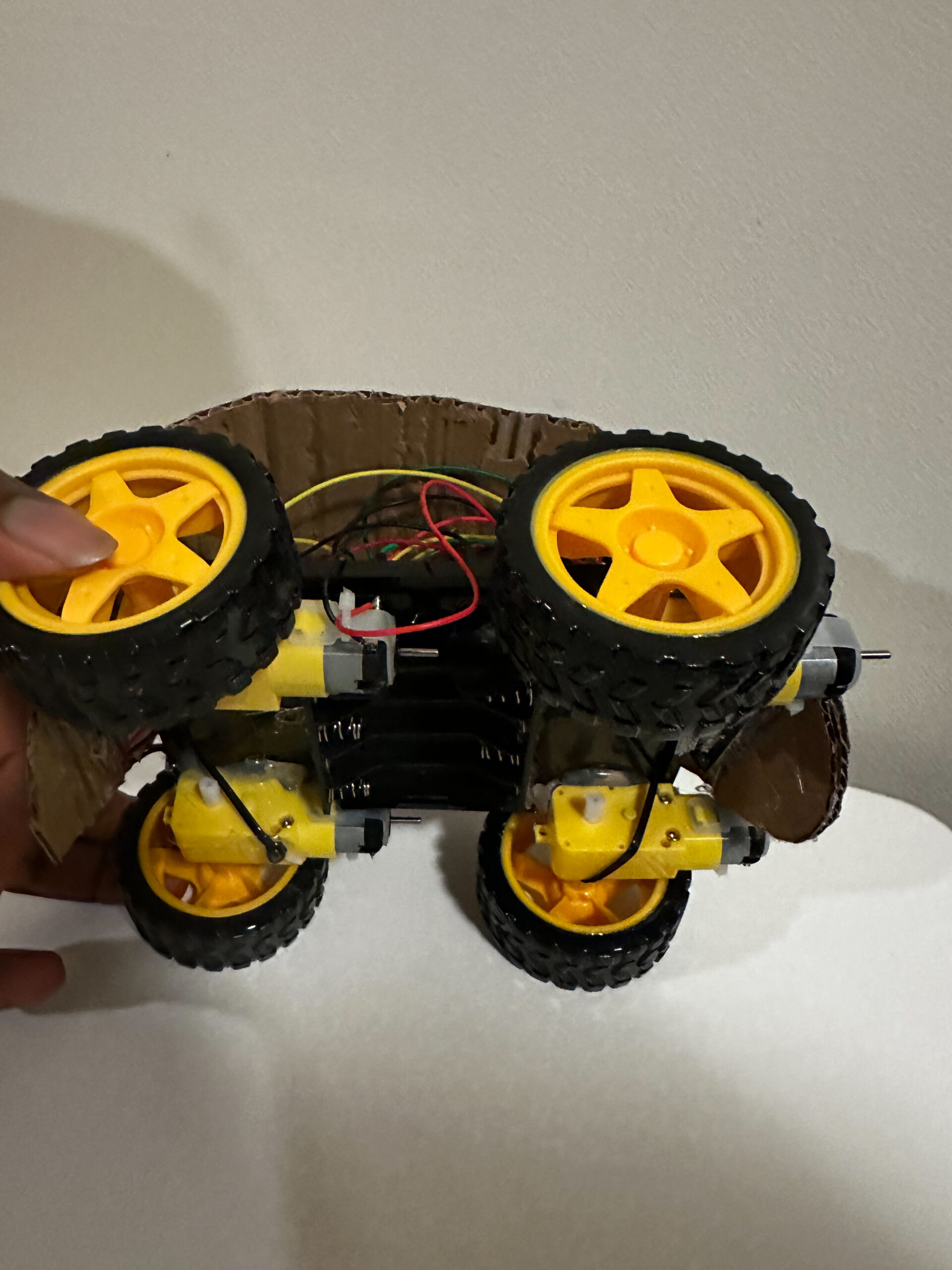
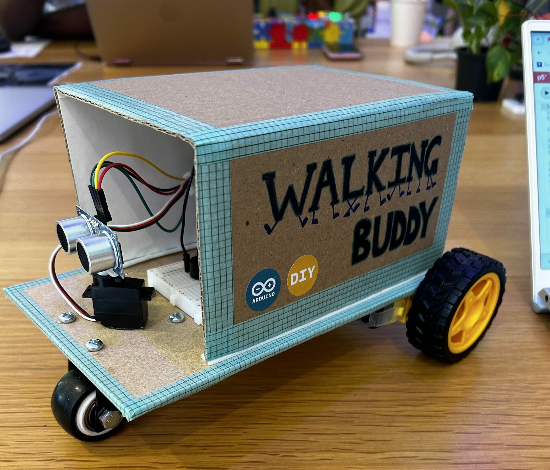
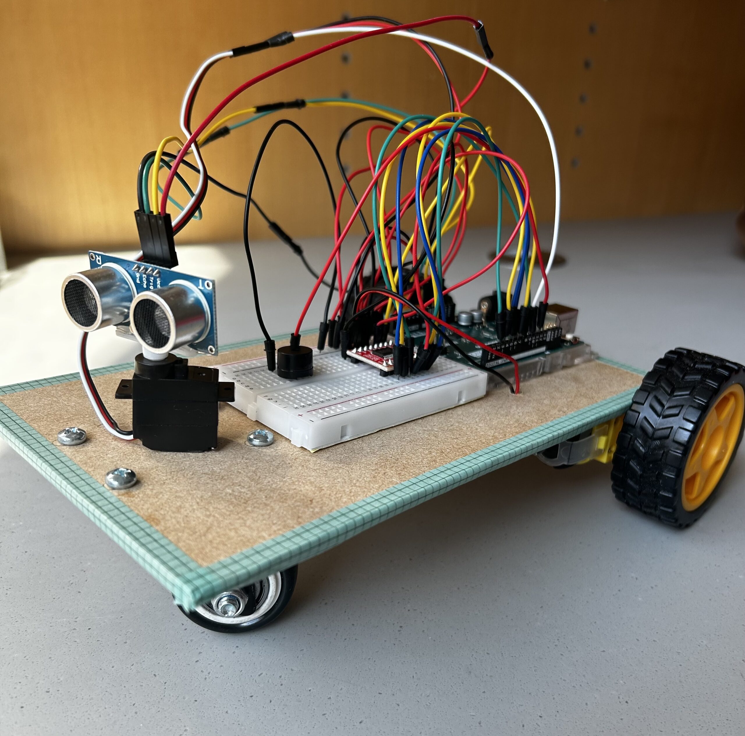
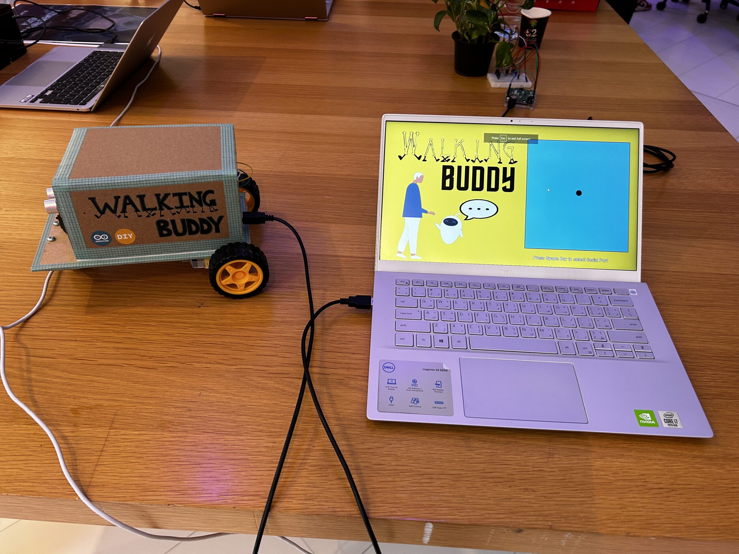
For the final project I was inspired to create an assistive device called “Walking Buddy” – a voice-controlled walking guide. Based on voice commands provided by the user, the robot changes direction and continues to move until the next command. If it encounters an obstacle, the robot stops and warns the user by playing a tune through the speaker. All the interaction involved is through voice and sound making the design inclusive for all users.


IMPLEMENTATION:

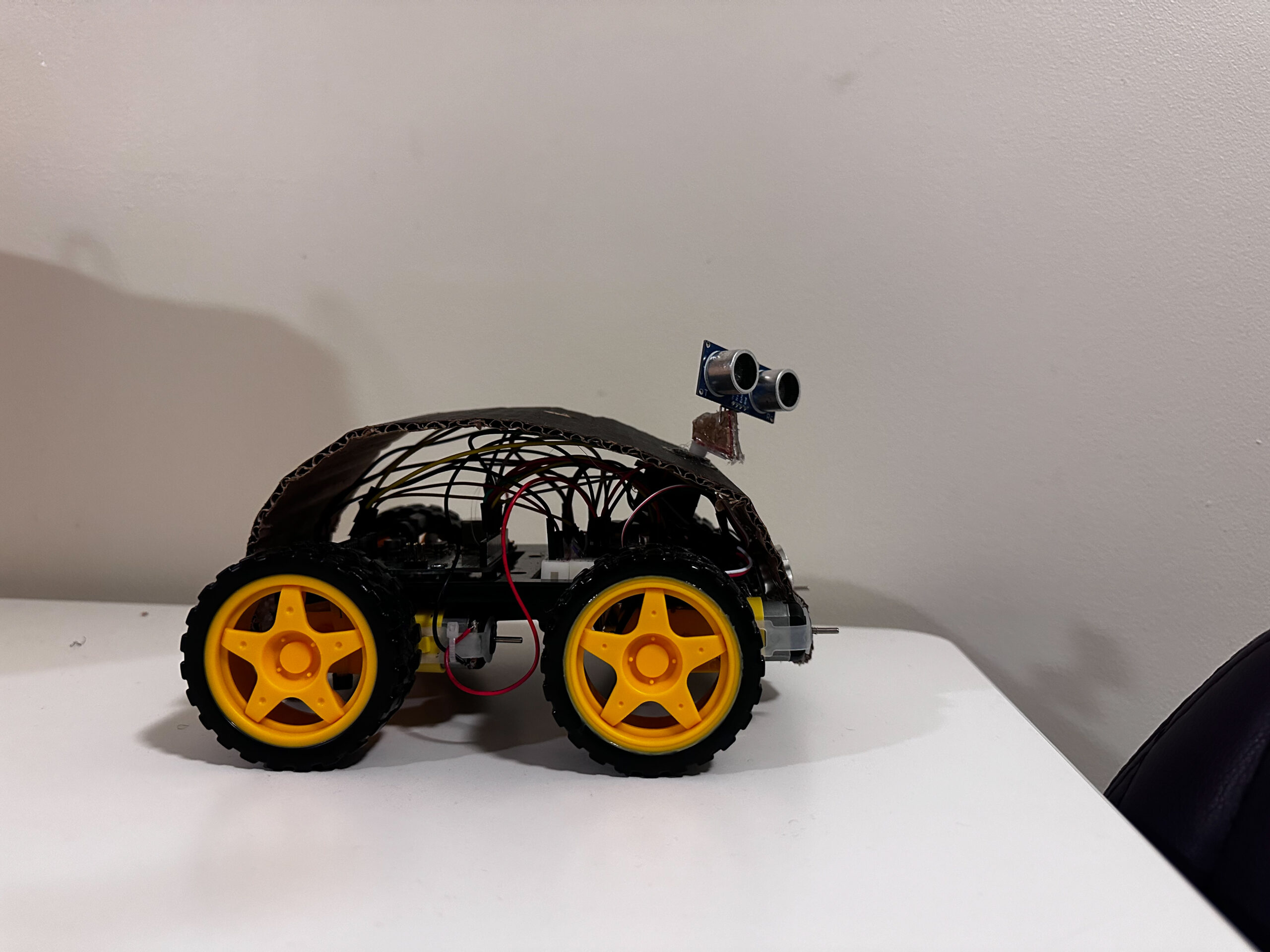
The communication begins through P5 where speech library has been used to create a code that infers the voice command and sends relevant data to the Arduino. After receiving the data, the Arduino checks the input received from the ultrasonic sensor, if there is no obstacle detected, it implements the direction of motors according to the command. However, in the presence of an obstacle it sends out a tune to warn the user and stop. Further, the ultrasonic sensor has been mounted on a servo motor which allows it to scan the surroundings before turning left or right. An additional feature that I added involves moving an ellipse in the p5 sketch based on the direction of movement of the robot.


ARDUINO CODE:

#include <Servo.h>
#include "pitches.h"

#define Echo A0
#define Trig A1
#define motor 10
#define Speed 170
#define spoint 103

const int ain1Pin = 3;
const int ain2Pin = 4;
const int pwmAPin = 5;

const int bin1Pin = 8;
const int bin2Pin = 7;
const int pwmBPin = 6;

// notes in the melody:
int melody[] = {
  NOTE_A3, NOTE_A3, NOTE_A3, NOTE_A3, NOTE_A3, NOTE_A3, NOTE_A3, NOTE_A3,
};

// note durations: 4 = quarter note, 8 = eighth note, etc.:
int noteDurations[] = {
  4, 4, 4, 4, 4, 4, 4, 4
};

char value;
int distance;
int Left;
int Right;
int L = 0;
int R = 0;
Servo servo;

void setup() {
  Serial.begin(9600);
  pinMode(Trig, OUTPUT);
  pinMode(Echo, INPUT);
  servo.attach(motor);
  pinMode(ain1Pin, OUTPUT);
  pinMode(ain2Pin, OUTPUT);
  pinMode(pwmAPin, OUTPUT);
  pinMode(bin1Pin, OUTPUT);
  pinMode(bin2Pin, OUTPUT);
  pinMode(pwmBPin, OUTPUT); 
  while (Serial.available() <= 0) {
    digitalWrite(LED_BUILTIN, HIGH); // on/blink while waiting for serial data
    Serial.println("0"); // send a starting message
    delay(300);            // wait 1/3 second
    digitalWrite(LED_BUILTIN, LOW);
    delay(50);
  }
}
void loop() {
  VoiceControl();
}

void moveBackward() {
  analogWrite(pwmAPin, Speed);
  digitalWrite(ain1Pin, HIGH);
  digitalWrite(ain2Pin, LOW);
  analogWrite(pwmBPin, Speed);
  digitalWrite(bin1Pin, HIGH);
  digitalWrite(bin2Pin, LOW);
}

void moveForward() {
  analogWrite(pwmAPin, Speed);
  digitalWrite(ain1Pin, LOW);
  digitalWrite(ain2Pin, HIGH);
  analogWrite(pwmBPin, Speed);
  digitalWrite(bin1Pin, LOW);
  digitalWrite(bin2Pin, HIGH);
}

void turnRight() {
  analogWrite(pwmAPin, Speed);
  digitalWrite(ain1Pin, HIGH);
  digitalWrite(ain2Pin, LOW);
  analogWrite(pwmBPin, Speed);
  digitalWrite(bin1Pin, LOW);
  digitalWrite(bin2Pin, HIGH);
}

void turnLeft() {
  analogWrite(pwmAPin, Speed);
  digitalWrite(ain1Pin, LOW);
  digitalWrite(ain2Pin, HIGH);
  analogWrite(pwmBPin, Speed);
  digitalWrite(bin1Pin, HIGH);
  digitalWrite(bin2Pin, LOW);
}

void stopMotors() {
  analogWrite(pwmAPin, Speed);
  digitalWrite(ain1Pin, LOW);
  digitalWrite(ain2Pin, LOW);
  analogWrite(pwmBPin, Speed);
  digitalWrite(bin1Pin, LOW);
  digitalWrite(bin2Pin, LOW);
}


int ultrasonic() {
  digitalWrite(Trig, LOW);
  delayMicroseconds(2);
  digitalWrite(Trig, HIGH);
  delayMicroseconds(10);
  digitalWrite(Trig, LOW);
  long t = pulseIn(Echo, HIGH);
  long cm = t * 0.034 / 2;; //time convert distance
  return cm;
}

int rightsee() {
  servo.write(20);
  delay(800);
  Left = ultrasonic();
  return Left;
}
int leftsee() {
  servo.write(180);
  delay(800);
  Right = ultrasonic();
  return Right;
}

void VoiceControl() {
  while (Serial.available()) {
    digitalWrite(LED_BUILTIN,HIGH);
    int value = Serial.parseInt();
    if (Serial.read() == '\n') {
      Serial.println(value);
      distance=ultrasonic();
      //Serial.println(distance);
      if (distance <= 12) {
        stopMotors();
        value=0;
        for (int thisNote = 0; thisNote < 8; thisNote++) {

          int noteDuration = 1000 / noteDurations[thisNote];
          tone(12, melody[thisNote], noteDuration);

          int pauseBetweenNotes = noteDuration * 1.30;
          delay(pauseBetweenNotes);
          // stop the tone playing:
          noTone(12);
        }
        
      }
      if (value == 3) {
        moveForward();
      } else if (value == 4) {
        moveBackward();
      } else if (value == 2) {
        L = leftsee();
        servo.write(spoint);
        if (L >= 10 ) {
          turnLeft();
        } else if (L < 10) {
          stopMotors();
        }
      } else if (value == 1) {
        R = rightsee();
        servo.write(spoint);
        if (R >= 10 ) {
          turnRight();
        } else if (R < 10) {
          stopMotors();
        }
      } else if (value == 0) {
        stopMotors();
      }
    }
  }
  digitalWrite(LED_BUILTIN,LOW);
}


P5 SKETCH AND  CODE:

let dir = 0;
let robotX, robotY;
let img1;
let title;
let speechRec;

function preload(){
  img1=loadImage("img.png")
  title=loadImage("title.png")
  speakImg=loadImage("speak.png")
}

function setup() {
  createCanvas(600, 400);
  robotX = 460;
  robotY = 195;
  
  let lang = navigator.language || "en-US";
  speechRec = new p5.SpeechRec(lang, gotSpeech);
  let speech = new p5.Speech();
  
  //Checks for the end of text-to-speech conversion
  speech.onEnd = () => {
    isSpeaking = false;
    let continuous = true;
    let interim = false;
    speechRec.start(continuous, interim);
  };
  isSpeaking = true;
  speech.speak('Hi there!,This is your walking buddy. Join me to explore the world on foot. Use the commands Right, Left, Forward, Backward and Stop to navigate the directions. Finally, remember to stop when you hear the siren.')
  

  function gotSpeech() {
    console,log("Speech")
    if (speechRec.resultValue) {
      createP(speechRec.resultString);
      //Conditions to detect the direction command
      if (speechRec.resultString.toLowerCase().includes("right")) {
        dir = 1;
      } else if (speechRec.resultString.toLowerCase().includes("left")) {
        dir = 2;
      } else if (speechRec.resultString.toLowerCase().includes("forward")) {
        dir = 3;
      } else if (speechRec.resultString.toLowerCase().includes("backward")) {
        dir = 4;
      } else if (speechRec.resultString.toLowerCase().includes("stop")) {
        dir = 0;
      }
    }
  }
}

function draw() {
  stroke(0);
  background("rgb(244,227,68)");
  image(img1,30,140,170,260)
  image(title,30,20,300,180)
  
  fill(146,196,248)
  rect(340,40,240,310)
  fill(0);
  ellipse(robotX, robotY, 20, 20);
  fill(255);
  textSize(15);

  if (!serialActive) {
    text("Press Space Bar to select Serial Port", 340, 380);
  } else {
    text("Connected", 3400, 380);
  }
  
  if (dir == 1) {
    stroke(255, 0, 0); // Red stroke for right
  } else if (dir == 2) {
    stroke(0, 255, 0); // Green stroke for left
  } else if (dir == 3) {
    stroke(0, 0, 255); // Blue stroke for forward
  } else if (dir == 4) {
    stroke(255, 255, 0); // Yellow stroke for backward
  } else {
    noStroke(); // No stroke for stop
  }
  noFill()
  strokeWeight(2)
  ellipse(robotX, robotY, 30, 30);
  
  if (dir==1 && robotX < width - 40){
    robotX+=0.5
  }
  else if (dir==2 && robotX > 360){
    robotX-=0.5
  }
  else if (dir==3 && robotY > 60){
    robotY-=0.5
  }
  else if (dir==4 && robotY < height-70 ){
    robotY+=0.5
  }
  if (isSpeaking) {
    image(speakImg, 180, 210, 100, 70);
  }
    
}

function keyPressed() {
  if (key == " ") {
    setUpSerial();
  }
}

function readSerial(data) {
  ////////////////////////////////////
  //READ FROM ARDUINO HERE
  ////////////////////////////////////

  if (data != null) {
    // make sure there is actually a message
    // split the message
   let fromArduino = split(trim(data), ",");
//     // if the right length, then proceed
    if (fromArduino.length == 1) {
    console.log(fromArduino[0]);
   }
    
    //////////////////////////////////
    //SEND TO ARDUINO HERE (handshake)
    //////////////////////////////////
    
    console.log(dir);
    let sendToArduino= dir + "\n";
    writeSerial(sendToArduino);
  }
}


The part of this project that I am proud of is achieving the voice control feature. I used ‘The Coding Train’ youtube tutorials to explore the p5 speech library and implemented both text-to-speech as well as speech-to-text conversions.

Coding Train Tutorial: https://youtu.be/q_bXBcmfTJM

CHALLENGES FACED:

Understanding the direction of movement of the motors was difficult initially but after a few trials I figured out the right code for each direction. Apart from this sending the text obtained from the commands of the user to the arduino did not always work as expected which made it challenging to understand what was wrong.

PROJECT TESTING VIDEOS:

The below videos include the robot following voice commands, detecting an obstacle and p5 screen.

https://drive.google.com/drive/folders/17U0GwIh4A0-HnNlQ5Dn-SARxTF9sP-2-?usp=drive_link

IM SHOW:

The showcase was a wonderful experience to see the creative work of others which also served as a sorce of inspiration for future projects. The concept of my project seemed interesting to people. However, I was encountered with an unanticipated situation where the robot was unable to work due to the detection of multiple sounds.

FURTHER IMPROVEMENT:

Some areas of future improvement would be to design a more efficient communication system with a precise description of the surrounding being conveyed to the user.

After the IM show, I felt that for such a robotic assistive device to be practical it would be necessary to have stronger sound selection to allow it to work even in crowded environments where multiple sounds can be detected.

Final Project: Human Following Robot

Concept

For my final project, I decided to create a human-following robot that I like to think of as a non-human pet, inspired by none other than Wall-E – that lovable robot from the movies. Just like Wall-E, my creation is meant to tag along beside you, sensing your presence and movement with its built-in sensors. It’s a robot that follows you around, imitating the way a curious pet might trail after its owner.

But there’s a twist – it’s not just an automatic follower. With P5JS, a programming tool, you get the reins, too. You can control it like you’re playing a video game, guiding it around with your keyboard and mouse. The idea struck me while watching Wall-E’s adventures, and I thought, why not blend that inspiration into something real? Something you can interact with, just like a pet that’s eager for your attention, whether it’s autonomously roaming or being directed by your commands.

Hardware Image

User Testing Videos

Key Components

  • Arduino Uno: The Arduino Uno acts as the brain of our robot. It’s a microcontroller responsible for processing data from sensors, making decisions, and controlling the motors and servo. The best part? It’s beginner-friendly, making it an ideal choice for those new to robotics.
  • Motor Driver: the powerhouse behind the robot’s movement. It precisely controls the motors that drive the wheels, ensuring our robot gracefully follows its human companion.
  • Ultrasonic Sensor: The ultrasonic sensor serves as the robot’s eyes, allowing it to measure distances. This is crucial for avoiding collisions and maintaining a safe following distance.
  • IR Sensor: Our robot needs to be smart enough to navigate around obstacles. That’s where the IR sensor comes in, allowing the robot to turn. By emitting and detecting infrared radiation, it enhances obstacle detection.
  • Servo Motor: It helps move the ultrasonic sensor, giving the robot flexibility.
  • Motors and Wheels: For our robot to follow, it needs reliable motors and wheels. The motor driver ensures these components work seamlessly, making our robot mobile and ready for adventure.
  • Piezo Speaker: Communication is key, even for robots. The piezo speaker provides audible feedback, alerting users that robots is ready to operate.

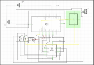
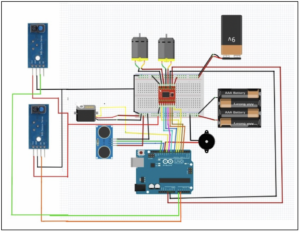
Schematic and Circuit Diagram

Implementation details

  • Interaction Design: The interaction design of my project centers on a user-friendly and intuitive experience. The robot operates in two modes: autonomous, where it uses sensors to follow the user around, and manual, where the user can control its movements through a P5JS interface. Switching between modes is seamless, catering to moments when you want a companionable presence without the effort or times when you prefer direct control.
  • Arduino Description: The Arduino code for my project serves as the brain of my pet-like robot. It integrates motor control with sensor inputs to enable the robot to follow a person autonomously or be controlled manually via P5JS. The code dictates how the robot moves in response to what the sensors detect, like proximity to objects or a person’s movements. It manages the logic for when the robot should move forward, turn, or stop to ensure smooth operation. Additionally, the code includes functions for playing melodies and controlling servo movements, giving the robot a lively and interactive character.

Code Snippet:

#include <SparkFun_TB6612.h>
#include "pitches.h"
#include <Servo.h>
//Motor Driver Pins
#define AIN1 3
#define BIN1 7
#define AIN2 4
#define BIN2 8
#define PWMA 5
#define PWMB 6
#define STBY 9

// Motor speed and control variables
const int offsetA = 1;
const int offsetB = 1;
int speed = 100;
int brightness = 0; // Variable to receive serial data for control

// Initialize motor objects with defined pins and offsets
Motor motor1 = Motor(AIN1, AIN2, PWMA, offsetA, STBY);
Motor motor2 = Motor(BIN1, BIN2, PWMB, offsetB, STBY);


//Ultrasonic Sensor
int distance;
long timetaken;
double feet, inch;

// Define ultrasonic sensor pins
#define echoPin 13
#define trigPin 12

// Define IR sensor pins
#define IRR A0  //pin for right sensor
#define IRL A1  //pin for left sensor


//Define Buzzzer pins
int speaker = 11;
int melody[] = {
  NOTE_C4, NOTE_G3, NOTE_G3, NOTE_A3, NOTE_G3, 0, NOTE_B3, NOTE_C4
};

// Melody and note durations arrays for the buzzer
int noteDurations[] = {
  4, 8, 8, 4, 4, 4, 4, 4
};

//Servo Motor initialization
Servo myservo;
int pos = 0; // Variable to store the servo position

void setup() {
    // Setup for ultrasonic sensor
  pinMode(trigPin, OUTPUT);  //ultrasonic sensor
  pinMode(echoPin, INPUT);

  // Setup for IR sensors
  pinMode(IRL, INPUT);  //left ir sensor
  pinMode(IRR, INPUT);  //right ir sensor

  //plays instrumental tones
  for (int thisNote = 0; thisNote < 8; thisNote++) {

    // to calculate the note duration, take one second divided by the note type.
    //e.g. quarter note = 1000 / 4, eighth note = 1000/8, etc.
    int noteDuration = 1000 / noteDurations[thisNote];
    tone(11, melody[thisNote], noteDuration);

    int pauseBetweenNotes = noteDuration * 1.30;
    delay(pauseBetweenNotes);
    // stop the tone playing:
    noTone(11); 
  }

  // Setup for servo motor
  myservo.attach(10);
  for (pos = 0; pos <= 180; pos += 1) {  // goes from 0 degrees to 180 degrees
    // in steps of 1 degree
    myservo.write(pos);  // tell servo to go to position in variable 'pos'
    delay(15);           // waits 15ms for the servo to reach the position
  }
  for (pos = 180; pos >= 0; pos -= 1) {  // goes from 180 degrees to 0 degrees
    myservo.write(pos);                  // tell servo to go to position in variable 'pos'
    delay(15);                           // waits 15ms for the servo to reach the position
  }
  pinMode(A3, OUTPUT);

  // Initialize Serial communication
  Serial.begin(9600);
}

void loop() {
    // Main loop for sensor reading and motor control
  int distance, readLeft, readRight;

  // Read ultrasonic sensor distance
  distance = ultra();
  Serial.println(distance);

    // Read IR sensor states
  readRight = digitalRead(IRR);
  readLeft = digitalRead(IRL);

  // Movement and control logic based on sensor readings
  if (readLeft == 1 && distance > 10 && distance < 25 && readRight == 1) {
    forward(motor1, motor2, speed); // Move forward
  } else if (readLeft == 1 && readRight == 0) {  //turn right
    left(motor1, motor2, speed);
  } else if (readLeft == 0 && readRight == 1) {  //turn left
    right(motor1, motor2, speed);
  } else if (readLeft == 1 && readRight == 1) {
    brake(motor1, motor2); // Brake the motors
  } else if (distance > 5 && distance < 10) {
    brake(motor1, motor2); // Brake if within a specific distance range
  } else if (distance < 5) {
    back(motor1, motor2, speed); // Move backward
  }

  // Remote control logic via Serial communication
  if (Serial.available() > 0) { // Check if there is any Serial data available
    // read the most recent byte (which will be from 0 to 255):
    brightness = Serial.read();

        // Conditional statements to control the robot based on the received byte
    if (brightness == 0) {
       // If the received byte is 0, move the robot forward
        // The function 'forward' is called with motors and speed as arguments
      forward(motor1, motor2, 200);
    } else if (brightness == 1) {
       // If the received byte is 1, move the robot backward
        // The function 'back' is called with motors and speed as arguments
      back(motor1, motor2, 200);
    }
  }
}


  •  Description of P5: In the P5.js code, there’s a dual-feature interface for my robot. It visually represents the sensor data, showing a value that decreases as you get closer to the robot and increases as you move away, mirroring the robot’s perception in real-time. Simultaneously, this interface allows you to control the robot’s movement. With simple commands, you can guide the robot to move forward or backward, offering a straightforward and interactive way to both visualize and manipulate the robot’s position and actions.

Code Snippet:

let serial; // variable for the serial object
let latestData = "wait"; // variable to hold the
let val = 0; // Variable to store a value for serial communication
let colorValue = 0;

function setup() {
  createCanvas(1000, 800);
  textSize(18);
  // serial constructor
  serial = new p5.SerialPort();

  // serial port to use - you'll need to change this
  serial.open("/dev/tty.usbmodem141101");

  // what to do when we get serial data
  serial.on("data", gotData);
}

// Callback function for processing received serial data
function gotData() {
  let currentString = serial.readLine(); // Read the incoming data as a string
  trim(currentString); // Remove any leading/trailing whitespace
  if (!currentString) return; // If the string is empty, do nothing
  console.log(currentString); // Log the data to the console for debugging
  latestData = currentString; // Update the latestData variable
}

function draw() {
  background(211, 215, 255);
  fill(102, 11, 229);

  // Map the latestData to a rotational degree value
  let rotDeg = map(latestData, 0, 1000, 0, 10000);

  // Check for the space bar key press to start
  if (key != " ") {
    // Display the starting screen
    textSize(30);
    fill(0, 0, 0);
    rect(0, 0, 1000, 800); // Draw a black rectangle covering the canvas
    fill(200, 200, 200); // Set text color
    text("PRESS SPACE BAR TO START THE HFR", width / 4, height / 2);
  } else {
    // Main interaction screen
    // Display forward and backward areas and instructions
    textSize(18);

    // Forward area
    fill(102, 11, 229);
    rect(890, 0, 110, 1000); // Draw the forward area
    fill(255, 245, 224);
    text("FORWARD", 900, 450); // Label for the forward area

        // Backward area
    fill(102, 11, 229);
    rect(0, 0, 110, 1000); // Draw the backward area
    fill(255, 255, 255);
    text("BACKWARD", 0, 450); // Label for the backward area

        // Draw the robot representation
    fill(35, 45, 63);
    rect(500, -100, 100, 600);  // Draw the robot's body
    fill(180, 101, 229);
    rect(500, 500, 100, -rotDeg); // Draw the robot's moving part

        // Additional robot features
    fill(200, 120, 157);
    rect(500, 500, 100, 80); // Base of the moving part
    fill(0, 0, 0);
    rect(460, 580, 40, -30); // Left wheel
    rect(600, 580, 40, -30); // Right wheel
    fill(255, 255, 255);
    text(latestData, 540, 560); // Display the latest data
    
        // Display control instructions
    fill("black");
    text("Control the Robot:\n\n", 470, 600);
    text(
      "Forward Movement:\n" +
        "- 'Forward' area on right\n" +
        "- Click to move forward\n" +
        "- Click again to stop\n\n",
      670,
      650
    );
    text(
      "Backward Movement:\n" +
        "- 'Backward' area on left\n" +
        "- Click to move backward\n" +
        "- Click again to stop\n\n",
      150,
      650
    );
    text("Move mouse to desired side and click to control movement!", 300, 770);
    textStyle(BOLD);


        // Serial communication based on mouse position
    if (!colorValue) {
      if (mouseX <= width / 2) {
        val = 1; // Set val to 1 if mouse is on the left half
        serial.write(val); // Send val to the serial port
        console.log("Left"); // Log the action
      } else {
        val = 0; // Set val to 0 if mouse is on the right half
        serial.write(val); // Send val to the serial port
        console.log("Right"); // Log the action
      }
    }
  }
    // Draw a circle at the mouse position
  fill(255, 255, 255);
  ellipse(mouseX, mouseY, 10, 10);
}
// Function to handle mouse click events
function mouseClicked() {
  if (colorValue === 0) {
    colorValue = 255;
  } else {
    colorValue = 0;
  }
}

  • Communication between Arduino and p5.js:

In this project, the Arduino sends sensor data to P5.js, allowing for a visual representation of proximity; the closer you are to the sensor, the lower the number, and vice versa. P5.js then sends back control commands to Arduino, enabling the user to maneuver the robot forward and backward. This bidirectional communication between Arduino and P5.js is streamlined through serial communication, using an application called SerialControl to effectively connect ports in P5.js. This setup ensures efficient data transfer and responsive control of the robot’s movements.

Something I am Proud of

I’m particularly proud of the hardware implementation aspect of my robot project. It was a journey that demanded considerable time, effort, and a variety of materials to reach the final outcome. The process of assembling and fine-tuning the hardware, from selecting the right sensors and motors to designing and building the physical structure, was both challenging and rewarding. Seeing the components come together into a functioning robot was a testament to the hard work and dedication put into this project. This aspect of the project stands out for me as a significant achievement.

Challenges Faced

One of the challenges I faced was with the P5.js control interface. When trying to remotely control the robot, it moved extremely slowly, and at times, it would completely stop responding, even though I was actively trying to move it. I spent a significant amount of time troubleshooting this issue, delving into various aspects of the code and communication protocols. Eventually, I came to realize that this might be a limitation within the system, possibly related to lag or processing delays, which seem to occur quite frequently.

Another challenge I encountered involved the power supply for the robot. Initially, I had a battery pack with four cells, totaling 6V, but my robot only required 4.5V. To adjust the voltage, I removed one cell and connected a wire to bridge the gap. However, this setup proved problematic; as the robot moved, the wire would shift its position, causing intermittent power loss and loss of control. The robot would continue moving uncontrollably until I reconnected the wire. To resolve this, I came up with a creative solution. I crafted a connector using aluminum foil, shaping it to fit securely on both ends of the battery compartment. This improvised connector ensured a stable connection, eliminating the issue of the wire shifting during movement. With this fix, the robot now operates smoothly without any control issues.

Future Improvements

In terms of future improvements for my project, one key area I’d like to focus on is enhancing the P5.js sketch to make it more interactive and engaging. I plan to introduce multiple pages within the sketch, each offering different functionalities or information, to create a more comprehensive and user-friendly interface. Additionally, I’m considering integrating sound into the P5.js environment. This could include audio feedback for certain actions or ambient sounds to make the interaction with the robot more immersive and enjoyable. These improvements aim to not only enrich the user experience but also add layers of complexity and sophistication to the project.

IM Show!

It was an honor to showcase my human-following robot at the IM show. Seeing the enthusiasm and curiosity of students and faculty members as they passed by to test my robot was a heartwarming experience. I was particularly thrilled to witness the interest of professors who have been integral to my learning journey. Among them was Evi Mansor, who taught me in the communications lab; her impressed reaction was a significant moment for me. Additionally, Professor Michael Shiloh, a well-known figure in the IM department, showed keen interest in my project. A special and heartfelt thanks goes to Professor Aya Riad, whose guidance and teaching were pivotal in developing the skills necessary to create such an innovative and successful outcome. The support and the lively interest of the audience made the event a memorable highlight of my academic journey.

Resources

  • https://youtu.be/yAV5aZ0unag?si=ZzwIOrRLBYmrv34C
  • https://youtu.be/F02hrB09yg0?si=d40SgnSfkBMgduA8
  • https://youtu.be/suLQpNPLzDo?si=G2rJR6YrsynycGoK
  • https://circuitdigest.com/microcontroller-projects/human-following-robot-using-arduino-and-ultrasonic-sensor
  • https://projecthub.arduino.cc/mohammadsohail0008/human-following-bot-f139db


Week 13 – Final Project – User Testing

Video

Are they able to figure it out? Where do they get confused and why? Do they understand the mapping between the controls and what happens in the experience?

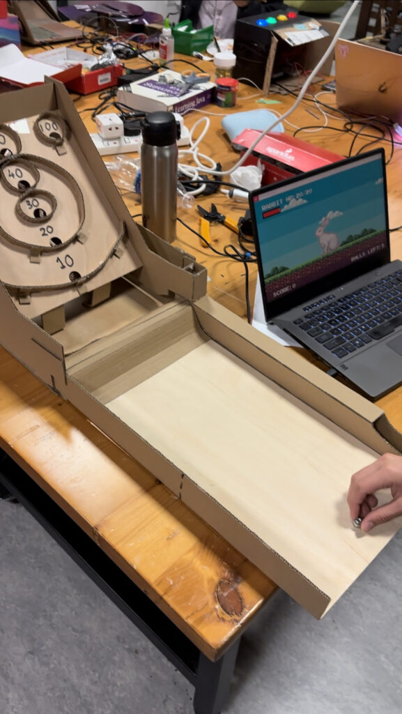
Some users did not know when to start playing the Skeeball machine after interacting with the p5.js sketch.

Some users also did not know how to play the skeeball machine, and it was a little frustrating for them as they kept missing the targets.

What parts of the experience are working well? What areas could be improved?

Users loved the instant feedback from hitting a target in the skeeball machine, and in general most users loved the p5.js sketch as they liked the art style and animations. They also liked the high score list.

The ball would sometimes get stuck in the machine, so users would be confused when the ball would not return.

What parts of your project did you feel the need to explain? How could you make these areas more clear to someone that is experiencing your project for the first time?

I often had to manually remove the ball from the machine when it got stuck. I could improve this experience by making the ball return mechanism work better, but I was not able to figure out a way of fixing it 100% of the time in the 2 hours I’ve spent trying to fix this thing.

I also had to show many users how to roll the ball, as some users would try to throw the ball which is not the intended way of playing. I could improve this by adding a screen to the front of the targets, so the only way to hit the targets is by rolling the balls up the ramp.

Final Project

BEATHOVEN

CONCEPT

The concept is inspired by Incredibox, a website first introduced in 2009 that offered a unique experience for creating music. No musical talent or knowledge of music composition is required. It’s designed so that any combination of audio seamlessly works with each other, allowing individuals to create their own music pieces. I found playing music on this website very satisfying and rewarding.

This inspiration drove the concept behind “Beat-Hoven.” Instead of different musical instruments, the music mixed is beatboxing. For the visuals, initially colorless avatars stand idle; once assigned a beatbox, their outfits change accordingly. Additionally, everything is kept in sync with an 8 sec cycle.

IMPLEMENTATION

First, I started by creating the basic mechanism of the project. I researched how buttons worked for the first time and created a small model of a single button that plays a beat when clicked. However, with this first step, I faced many issues. The first button I used was faulty, which took me a lot of time to realize. Next, I realized that a single button press sent multiple true values at once instead of the one return value I was looking for. This caused a lot of issues with the implementation of the button; however, I figured out how to fix the problem.

Next, I started creating the foundation of the project by connecting the button press to start the audio of the intended player. The first issue I faced was how to send an instruction to stop the audio. Since the button only sends a high signal when pressed, I had to interpret it and check if the button pressed was intended to start or stop the audio. I was able to do that with a few checks, if functions, and flags.

After figuring out the start and stop of the audio, it was time to implement it on a larger scale. I started soldering the rest of the buttons and got them ready. Then I started importing the audio assets to each character one by one to p5. After that, I started linking them to the audio and adjusting the Arduino code to accommodate the buttons.

However, the challenges were not over. The next problem was creating the cycle that decides when an audio is played and when it is stopped to keep the beats in sync. Unfortunately, Google wasn’t helpful in any of the problems I faced since everything worked differently in my code. After 3 hours of figuring it out, I moved on to the next problem: Images! Since I had 8 characters, each character had its own audio, image, and logo. It was the image stage, and I faced many issues, especially since I had a background that was refreshing with each loop. The character that appeared when the button was pressed disappeared since the background was called in the next frame. I had to redesign the whole page to accommodate this.

After figuring that out and adjusting it so that the characters change when they’re not playing, I had to find a way to inform the user that the button-pressed signal has been received. I had this problem since the character does not play until the new cycle starts. So, if the user selected a character between cycles, they would not know if the press was successful or not, and they would press again, which would deactivate the character. I decided to use their logos. One would be colored, and the other monochrome, symbolizing that the character is not selected. After implementing it and linking it with a new function, the project started to take its form.

The next step was to work on the aesthetics. I designed a logo for the page, decided on the iconic name “Beat-Hoven,” and designed the homepage. However, the homepage was missing something – music! I found a mix that was created using beatbox and applied it for the background music. Next, I created the info page that explained the game. Now, the code was almost done, and it was time to work on the container design. I designed the box using a template from the web and laser-cut it on acrylic. Next, I assembled everything into the container and drilled a hole for the Arduino data wire. Finally, I printed an image of the characters and attached it to the box to make it stand out. And with this the project was completed.

 For the Arduino code:

I used 8 buttons which the Arduino received signals from and sent it to p5. It has a delay to only receive one input from the button per press to avoid the spamming of inputs.

For the p5

There are so many checks to ensure the program runs smoothly.
  • receives the input of the button
  • turns the flag related to the character to active if not active and turns it off if active
  • checks to see the next cycle has started
    • if activation flag is active
      • activate the character audio and display the image
    • if flag is deactivated
      • deactivate the character, stop the audio and change the image
  • parallel check
      • if the activation flag is active
        • display the colored logo immediately and do not wait for the new cycle
      • if flag is deactivated
        • display the monochrome logo for the character
      • if the page title is pressed
        • deactivate all characters
        • turn all the flags to deactivated.
        • return to the main page
        • start the background music
      • if the info page is pressed
        • switch the page and do not turn off the background music

Aspects I am particularly proud of

There are so many to mention, but here’s a few

creating a fully functioning game that was created by a team of professionals in a few days and nights

figuring out ways around the obstacles I faced

project turning out to be better than I imagined and not just satisfying the goals

learning how to use a laser cutter and how to solder for the first time

Areas for improvement

I would love to add animation to the phase to be in sync with the audio and maybe another version with different characters.

BEATHOVEN:

Showcase: showcase


Week 13- Final Project User Testing

I had two of my friends try the project during user testing. While conducting the test, I connected the p5.js sketch to the Arduino, displayed the sketch in full screen, and left the users to determine how to interact with both the box and the screen. Even though they were mentioned in the instruction that was displayed on the screen, users were uncertain about interacting with the box and screen simultaneously. So I needed to explain that they would receive hints on the screen and input the code using the button and knob on the box.

About the guessing the code, they quickly understood how to use the hints to guess the three digits required to unlock the code. However, they found it confusing regarding how to backtrack and edit an entered code if they wanted to change one of the digits, which is not possible in the game. And that was missing in the instruction.

In this vide the user is trying to crack the code for the second time: https://youtube.com/shorts/YVequMRq7eI?feature=shared

After user testing, I decided to add instructions on how to enter the code and clarify that editing the already entered code was not an option. Also, I chose to include printed instructions on the box, indicating users should gather hints from the screen to input the digits accordingly.

Week 13 – Final Project – Skeeball Dungeon

Describe your concept

I wanted to make an arcade machine for my final project, and my initial idea was a pachinko machine. However, I pivoted away from that as I couldn’t think of a good way to integrate P5.js into that project, and decided to make Skeeball instead.

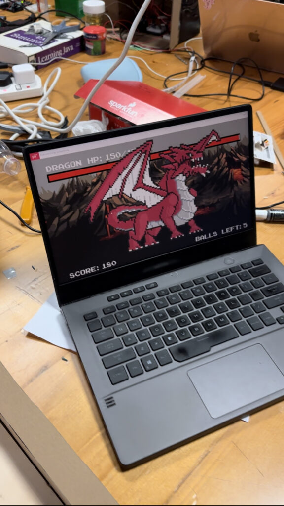
My project is basically skeeball, with a touch of an RPG battle concept, hence the very creative name ‘Skeeball Dungeon’. The player will have to fight 4 increasingly tougher opponents in P5.JS, and they the damage they do is equal to the amount of points they get in skeeball. For each opponent, they are given 5 balls, and they have to defeat the opponent in the number of given balls.

Include some pictures / video of your project interaction

p5.js battle! skeeball !

Description of interaction design

The p5.js sketch is used to display instructions, showing high scores, visualizing the battles and hold the graphics. The Arduino is used to obtain information from the user playing Skeeball, detecting when a target has been hit and how many points was obtained.

Description of Arduino code and include or link to full Arduino sketch

The Arduino was used to detect when targets has been hit in the Skeeball physical component. To detect when a target has been hit, a flex sensor is used for each hole. When the ball passes through the hole, the Arduino pin input that is connected through the flex sensor-voltage divider circuit will have a lower/higher reading. This change is reading is then used to detect when a target has been hit.

Description of p5.js code and embed p5.js sketch in post

https://editor.p5js.org/ojmjunming/sketches/V0ARmZA70
The p5.js code holds all of the battle logic and the screens. A state system is used to transition between each different ‘screen’ to make the code more readable. e.g the first screen, instructions and more.

if (currentScene === "highScore") {
    highScoreScreen();
  } else if (currentScene === "instructions") {
    instructionScreen();
  } else if (currentScene === "battle") {
    renderBattleScreen();
  }

The code also keeps track of the health of the monster, the current monster, the score and the number of balls. The Arduino does not know how many balls are left, it only communicates the ball hits to p5.js. The p5.js sketch also maintains a top 5 list of high scores.

Description of communication between Arduino and p5.js

The Arduino will send a message of length 2 a single time when a target is hit. Otherwise, it sends a garbage message of length 1. The message contains the amount of points that was scored with that hit. The p5.js will continuously handshake with Arduino, most of the time the data is useless (when it’s length 1), and when the length is 2, it means that a target has been hit and the message will be processed, dealing damage to the monster equivalent to the points scored.

What are some aspects of the project that you’re particularly proud of?

There were some really interesting problems that I was proud of solving:
1) Constructing the Skeeball machine.
I originally planned to use the laser cutter to build the physical component, but the laser cutter only managed to cut out one piece before it started acting up. I waited 3 hours and the laser cutter was still not working. So, I pivoted to making it with cardboard and wood pieces, using tons of hot glue but it turned out to be surprisingly stable so I’m pretty proud of the machine itself as it took me a lot of time.

2) 7 flex sensors, but only 6 analog inputs on the Arduino Uno.

I was using flex sensors to detect target hits, but I had 7 targets/holes but only 6 analog inputs. Remembering that a digitalPin reads HIGH or LOW voltages (2.5-5V, 0-2.5V), I constructed a voltage divider with 30K resistors, so the analog reading teetered on the edge of 2.4-2.6V (480-530 analogInput) depending on the flex of the flex sensor. Knowing this, I was able to use a digitalPin to read the flex of the sensor ( the other sensors were read with a analogPin, which was much easier ). When the sensor is flexed, the reading would change from HIGH to LOW.

What are some areas for future improvement?

The skeeball machine could have been constructed better, as I did not have time to paint or decorate it well. The ball also sometimes gets stuck while it’s attempting to return to the start tray and you have to manually push it out. I also had to scrap an idea I had of detecting missed ball hits, as I wasn’t able to figure out how to attach a sensor for that, so in the future it would be nice to be able to include that in my game.

Saiki Final Project: Motion Tracking CCTV Camera

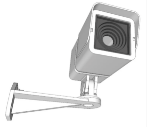
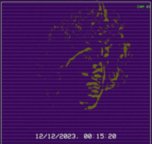
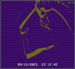
My final project is a motion tracking CCTV camera that utilizes poseNet. The basic idea is to use poseNet to locate a person on the screen, and then send that data to a 3D printed CCTV camera mounted on top of a servo motor. By mapping the location data to the angles of the servo motor, it creates the illusion that the CCTV camera is following the person. In addition to the camera tracking, I also wanted to create a motion detecting p5 interface. After watching coding train tutorials on this effect, I discovered a method that uses pixel array data to isolate the moving person from the background, which I found really cool.

A large part of my process involved testing whether the servo-poseNet idea would work or not, and my draft of the final project documents this discovery. For the final project, I had several challenges ahead of me, including creating the p5 interface, figuring out the CCTV camera, and building a base for the camera and motor.


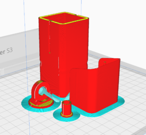
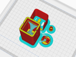
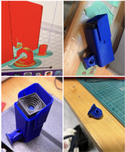
First, with the CCTV camera, I referred to the professor’s slides and came across a website with various 3D models that could be 3D printed. With the professor’s guidance on using the Ultimaker 3, I successfully 3D printed a CCTV camera that was the perfect size for the motor, in my opinion.


Next, I focused on the p5 interface. As mentioned earlier, I aimed to achieve a motion detection look. By applying multiple layers of effects such as grain, blur, and posterize, I was able to create an old-school CCTV footage vibe while also giving it a unique appearance that doesn’t resemble a typical CCTV camera. I wanted to capture the point of view of a camera trying to detect motion.

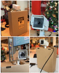
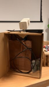
The final step for me was priming and spray painting the CCTV camera white, and finding the right base for it. Since I wanted to position it behind the laptop, I needed a base of suitable height. I found a cardboard box in my room and repurposed it as the shell for the CCTV camera base. I drilled a large piece of wood into it, which serves as a sturdy base for the motor. I then used wood glue to attach the motor to the wood slab, and glued the motor’s base plate to the CCTV camera.

The following is the code for my Arduino and p5 project:

// video, previous frame and threshold for motion detection
let video; 
let prev;
let threshold = 25;

// Variables for motion functions and positions

let mfun = 0;
let motionY = 0;

let lerpX = 0;
let lerpY = 0;

// Font for overlay text and PoseNet related variables

let myFont;
let poseNet;
let pose;
let skeleton;
let loco = 0;

function preload() {
  myFont = loadFont("VCR_OSD_MONO_1.001.ttf");
}

function setup() {
//   low frame rate for a cool choppy motion detection effect
  frameRate(5);

  createCanvas(windowWidth, windowHeight);
  pixelDensity(1);

  video = createCapture(VIDEO);
  video.size(windowWidth, windowHeight);
  video.hide();

    // Create an image to store the previous frame

  prev = createImage(windowWidth, windowHeight);

    // Initialize PoseNet and set up callback for pose detection

  poseNet = ml5.poseNet(video, modelLoaded);
  poseNet.on("pose", gotPoses);
}

// Callback for when poses are detected by PoseNet

function gotPoses(poses) {
  //console.log(poses);
  if (poses.length > 0) {
    pose = poses[0].pose;
    skeleton = poses[0].skeleton;
  }
}

// Callback for when PoseNet model is loaded

function modelLoaded() {
  console.log("poseNet ready");
}

function draw() {
  
//   Check for serial port
  if (!serialActive) {
    text("Press Space Bar to select Serial Port", 20, 30);
  } else {
    text("Connected", 20, 30);
  }
  
//   Check for pose and get nose pose data

  if (pose) {
    fill(255, 0, 0);
    ellipse(pose.nose.x, pose.nose.y, 20);

//     location of pose nose
    loco = int(pose.nose.x);
//     value mapped for servo motor
    val = int(map(loco, 0, windowWidth, 60, 120));

    print(val);
  }
  
  
  background(0);
// load pixels for motion detection
  
  video.loadPixels();
  prev.loadPixels();

  threshold = 40;

  let count = 0;
  let avgX = 0;
  let avgY = 0;

  // Flip the canvas for video display
  push();
  translate(width, 0);
  scale(-1, 1);
  image(video, 0, 0, video.width, video.height);
  pop();

    // Analyzing the pixels for motion detection

  loadPixels();
  for (let x = 0; x < video.width; x++) {
    for (let y = 0; y < video.height; y++) {
            // Current and previous pixel colors

      let loc = (x + y * video.width) * 4;
      let r1 = video.pixels[loc + 0];
      let g1 = video.pixels[loc + 1];
      let b1 = video.pixels[loc + 2];
      let r2 = prev.pixels[loc + 0];
      let g2 = prev.pixels[loc + 1];
      let b2 = prev.pixels[loc + 2];

      // Calculate color distance

      let d = distSq(r1, g1, b1, r2, g2, b2);

      if (d > threshold * threshold) {
        avgX += x;
        avgY += y;
        count++;
        
        // Fliped motion effect pixels
        let flippedLoc = (video.width - x - 1 + y * video.width) * 4;
        pixels[flippedLoc + 0] = 155;
        pixels[flippedLoc + 1] = 155;
        pixels[flippedLoc + 2] = 255;
      } else {
        let flippedLoc = (video.width - x - 1 + y * video.width) * 4;
        pixels[flippedLoc + 0] = 190;
        pixels[flippedLoc + 1] = 255;
        pixels[flippedLoc + 2] = 155;
      }
    }
  }

    // Updating the pixels on the canvas

  updatePixels();

    // Calculate the average motion position if significant motion is detected

  if (count > 200) {
    motionX = avgX / count;
    motionY = avgY / count;
  }

  // Mirror the motion tracking coordinates
  //     let flippedMotionX = width - motionX;

  //     lerpX = lerp(lerpX, flippedMotionX, 0.1);
  //     lerpY = lerp(lerpY, motionY, 0.1);

  //     fill(255, 0, 255);
  //     stroke(0);
  //     strokeWeight(2);
  //     ellipse(lerpX, lerpY, 36, 36);
  
//   MOREE EFFECTZZZZ

  filter(INVERT);
  prev.copy(
    video,
    0,
    0,
    video.width,
    video.height,
    0,
    0,
    prev.width,
    prev.height
  );
  filter(ERODE);
  filter(POSTERIZE, random(10, 20));
  
  drawGrid(); // Draw the grid on top of your content

  drawSurveillanceOverlay(); //surveillance overlay cam
  drawGrain(); // grain effect for old school cctv vibes

  filter(BLUR, 1.5); // blur effect to achieve that vhs quality
}

function distSq(x1, y1, z1, x2, y2, z2) {
  return sq(x2 - x1) + sq(y2 - y1) + sq(z2 - z1);
}

  // toggle full screen

function mousePressed() {
  if (mouseX > 0 && mouseX < width && mouseY > 0 && mouseY < height) {
    let fs = fullscreen();
    fullscreen(!fs);
  }
}


function drawGrain() {
  loadPixels();
  for (let i = 0; i < pixels.length; i += 4) {
    let grainAmount = random(-10, 10);
    pixels[i] += grainAmount; // red
    pixels[i + 1] += grainAmount; // green
    pixels[i + 2] += grainAmount; // blue
    // pixels[i + 3] is the alpha channel
  }
  updatePixels();
}

function drawSurveillanceOverlay() {
  textFont(myFont); // Set the font
  textSize(32); // Set the text size
  
  // Draw border
  noFill();

  strokeWeight(5);

  stroke(0, 0, 0, 255);

  rect(9, 9, width - 16, height - 16);
  stroke(250, 250, 250, 255);
  strokeWeight(2.1);

  rect(9, 9, width - 16, height - 16);

  // Display timestamp
  fill(250, 50, 50);
  fill(250, 250, 250);

  stroke(0, 120);

  textSize(30);
  textAlign(CENTER, TOP);
  text(
    new Date().toLocaleString(),
    windowWidth / 2,
    windowHeight - windowHeight / 11
  );

//  cam 01
  textSize(17);
  fill(50, 250, 55);
  text("CAM 01", width - width / 19, windowHeight / 29);
}

function drawGrid() {
  let gridSize = 15; // Size of each grid cell
  
//   only the horizontal lines

  stroke(205, 3); // Grid line color (white with some transparency)
  strokeWeight(1); // Thickness of grid lines

  for (let x = 0; x <= width; x += gridSize) {
    for (let y = 14; y <= height + 16; y += gridSize) {
      // line(x, 10, x, height);
      line(11, y, width - 10, y);
    }
  }
}

// serial connection
function keyPressed() {
  if (key == " ") {
    // important to have in order to start the serial connection!!
    setUpSerial();
  }
}

function readSerial(data) {
  ////////////////////////////////////
  //READ FROM ARDUINO HERE
  ////////////////////////////////////

  if (data != null) {
    // make sure there is actually a message
    // split the message
    let fromArduino = split(trim(data), ",");
    // if the right length, then proceed
    if (fromArduino.length == 2) {
      // only store values here
      // do everything with those values in the main draw loop
      print("nice");
      // We take the string we get from Arduino and explicitly
      // convert it to a number by using int()
      // e.g. "103" becomes 103
    }

    //////////////////////////////////
    //SEND TO ARDUINO HERE (handshake)
    //////////////////////////////////
    let sendToArduino = val + "\n";
    writeSerial(sendToArduino);
  }
}

p5 👆

#include <Servo.h>

Servo myservo;  // create servo object to control a servo


void setup() {

  Serial.begin(9600);

  myservo.attach(9);

  // start the handshake
  while (Serial.available() <= 0) {
    digitalWrite(LED_BUILTIN, HIGH); // on/blink while waiting for serial data
    Serial.println("0,0"); // send a starting message
    delay(300);            // wait 1/3 second
    digitalWrite(LED_BUILTIN, LOW);
    delay(50);
           myservo.write(0);                  // sets the servo position according to the scaled value

  }
}

void loop() {
  // wait for data from p5 before doing something
  
  while (Serial.available()) {
    Serial.println("0,0");
    digitalWrite(LED_BUILTIN, HIGH); // led on while receiving data
    int value = Serial.parseInt();
    if (Serial.read() == '\n') {
       myservo.write(value);                  // sets the servo position according to the scaled value
    }
  }
}

arduino 👆

Overall, I am happy with how the project was realized. It has been a very educational experience for me, as it has allowed me to learn about posenet, 3D printing, and visual effects. These skills will be valuable for my future capstone project, which will focus on surveillance.


Documentation/User Testing from the IM Showcase:


Final Project: Automated Trash Sorting System: A Sustainable Waste Solution

Automated Trash Sorting System: A Sustainable Waste Solution

Concept:

The project’s main goal is to develop a trash sorting system that can help the environment in several ways. This system relies on technologies like Arduino, capacitive, and IR sensors to automatically detect and sort different types of objects placed in a trash bin, distinguishing between plastic and general waste. This technology offers several environmental benefits.

The automatic trash sorting system helps make sure that things we can recycle, like plastic, don’t get thrown away in the trash and sent to landfills. When plastic items are sorted out from regular trash, we can recycle them correctly, which saves important materials and reduces the amount of new plastic things we have to make. This is good for the environment because it means less pollution from plastic and less energy used to make new plastic stuff.

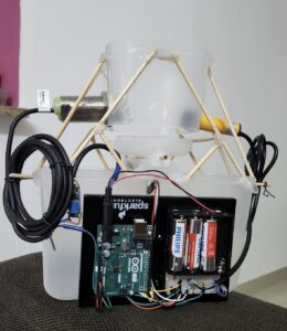
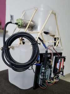
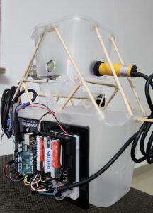
Images of the project:


Components: 

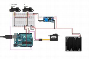
Arduino uno

battery with 6 volts

IR sensor: E18-D80NK Adjustable Infrared Sensor

Capacitive sensor: Autonics Proximity Sensors Capacitive Sensors CR30-15DN

DC to DC boost converter : (the dc to dc boost converter employing a switching circuit and energy storage components like inductors and capacitors, increases the input voltage to a higher level through controlled switching and energy transfer processes.)


Schematic:

Videos:

User testing

How does the implementation work?

The project’s implementation consists of a smart system that uses technology to make things work. It uses an Arduino and P5.js . The Arduino has a special sensor called a capacitive sensor, which can figure out what kind of material something is made of. For example, it can tell if it’s plastic or something else. Additionally, there’s another sensor called an IR sensor. This sensor can figure out if there’s something in the trash bin or not. To make it even more useful, the project also has a web interface made with p5.js. Where you can control and change how the system works. It’s like having a remote control for your TV but for this trash sorting system. So, with the web interface, you can tell the system what to do, like sorting the trash in different ways or turning it on and off. This makes it easier for people to use and control the system the way they want.

Sensors:

IR Sensor: (Digital)

The infrared sensor has 2 leds, one for sending the infrared light and the second for receiving it. So if there is an object in front of the sensor the light will be reflected from the object back to the sensor. The IR sensor detects if there is an object present or not but it doesn’t know the material of the object. If the signal is high it means there is no object and if its low means there is an object. 5 volts high and low 0 volts.

Capacitive sensor: (Digital)

Capacitive sensors- the change in electric field that can detect if there is an object or not (also depends on the sensitivity/distance). The purpose of capacitive sensor in this project is to detect if the object is not plastic, it can detect conductive objects. When the IR sensor detects an object then it checks the capacitive sensor if the voltage is high (10volts) then the object is general (conductive) if the voltage is low (0volts) then the object is plastic or inductive

Description of interaction design:

The interaction design of the system is all about how people can use and communicate with it. In this case, users can interact with the system through the p5.js web interface, which is like a control panel on a computer screen.

Inside this interface, there are buttons that you can click on. These buttons allow you to do different things. For example, there are buttons that let you choose how the system works, like whether it should do things automatically by itself (automatic mode) or if you want to control it yourself (manual mode). This is similar to choosing between letting a robot do a task for you or doing it with your own hands.

There are also buttons to tell the system what kind of material you’re putting in the trash. You can say if it’s plastic or something else (general waste). This helps the system know what to do with the trash.

To make things even clearer, the interface shows you text on the screen. This text tells you what mode the system is in and what kind of material it’s looking for. This way, you can always see and understand what the system is doing.

Description of Arduino code + code snippets:

The Arduino code uses Servo and defines the pins for capacitive and IR sensors. It reads incoming serial data, processes the angle value, and adjusts the servo accordingly. Modes (automatic/manual) and sensor readings are also handled.

Include the servo library and define the pins with required variable:

#include <Servo.h>;

Servo GateServo;

#define capSensor A3 //Pin A3 (analog)
#define irSensor 4 //Pin 4 (digital)
#define GateServoPin 3 // GateServo pin

bool openTrash = false;
bool autoMode = true;

//Plastic goes to angle 11
//General goes to angle 158
//The closing angle of the gate which is 85 degree
 
int initialServoPosition = 85;
int anglePlastic = 11;
int angleGeneral = 150;

int capValue;

unsigned long GateServoReturnTime = 0;
const unsigned long GateServoReturnDelay = 1000; // 1 seconds in milliseconds

Receive data from p5js via serial connection and extract the angle for plastic and general:

void loop()
{
  while (Serial.available() > 0) {
    // Read the angle value from serial
    String incomingData = Serial.readStringUntil('\n');

    //If the mode is manual enable controlling by the p5js panel
    if (!autoMode) {
      // Check if the incoming data starts with "angle:"
      if (incomingData.startsWith("angle:")) {
        // Extract the angle value from the incoming data
        int angleValue = incomingData.substring(6).toInt();
  
        // Process the angle value if it is within the valid range
        if (angleValue >= 11 && angleValue <= 158) {
//          Serial.println("Received angle: " + String(angleValue));
          // Set the GateServo angle
          GateServo.write(angleValue);
  
          // Reset the timer each time a valid angle is received
          openTrash = true;
          GateServoReturnTime = millis();
        }
      }
    }

Get the working mode from p5js panel and control the servo:

 if (incomingData.startsWith("Auto")) {
      autoMode = true;
//      Serial.println("Auto mode: " + String(autoMode));
    }
    else if (incomingData.startsWith("Manual")){
      autoMode = false;
//      Serial.println("Manual mode: " + String(autoMode));
    }
  }

  // Check if it's time to return the GateServo to 85 degrees
  if (millis() - GateServoReturnTime >= GateServoReturnDelay && openTrash) {
    openTrash = false;
    GateServo.write(initialServoPosition);
//    Serial.println("Trash Closed");
  }


Description of p5.js code + Embedded p5.js sketch: 

The p5.js code controls the web interface, buttons, and communication with Arduino. It displays the current mode, material type, and provides buttons for user interaction.

Description of communication between Arduino and p5.js:

Communication between Arduino and p5.js is achieved through the serial port. The p5.js script sends commands for mode setting and material type selection, and the Arduino reads and processes these commands, adjusting the servo and handling sensors accordingly.

The breakdown of the bidirectional communication:

1. p5.js to Arduino:

  • Sending Commands & Data: In p5.js, the serial.write(data) function is to send data to the Arduino. This data could be commands, sensor readings, or any other information needed to be sent to the Arduino.
  • Receiving in Arduino: On the Arduino side, the Serial.available() to check if there’s data available in the serial buffer. If data is available, the functions erial.readStringUntil(‘\n’) is to read and process the incoming data.

2. Arduino to p5.js:

  • Sending Data from Arduino: In Arduino code, the Serial.print(), Serial.println() send data back to the p5.js sketch over the serial port. This could be sensor readings, or any information needed to be visualized or processed in p5.js.
  • Receiving in p5.js: In the p5.js sketch ,the serial. on(‘data’, gotData) event to define a function (gotData) that will be called whenever new data is received. Inside this function, the incoming data will be processed.

What are some aspects of the project that you’re particularly proud of?

The seamless integration of hardware components, the user-friendly p5.js interface, and the efficient sorting mechanism underscores the project’s success in creating a functional and user-centric waste disposal system. These achievements not only enhance the user experience but also promote environmentally responsible waste management practices by automating the segregation process based on detected material types.

Challenges faced and how you tried to overcome them:

Challenges included sensor calibration, ensuring real-time communication between Arduino and p5.js, and optimizing the sorting algorithm.

    • Sensor Calibration and Accuracy:One of the primary challenges encountered during the project was ensuring accurate sensor readings for object detection. The capacitive and IR sensors required precise calibration to reliably distinguish between plastic and general waste. To address this, an extensive calibration process was undertaken, involving systematic adjustments to sensor thresholds, distances, and environmental conditions. Regular testing with a variety of objects helped fine-tune the sensor parameters, improving the overall accuracy of material classification.
    • Real-time Communication:Achieving seamless and real-time communication between the Arduino and the p5.js web interface was another significant challenge. Ensuring that commands were sent and received promptly without delays was crucial for responsive user interaction.

What are some areas for future improvement?

There are several exciting possibilities for future improvements to make the system even better and more efficient.

One area of improvement could focus on enhancing the sorting algorithm. Right now, the system can distinguish between plastic and general waste, but in the future, it could be trained to recognize and sort a wider range of materials. For example, it could learn to separate paper, glass, and metal items, increasing the effectiveness of recycling and reducing waste even further.

Another exciting advancement could involve implementing machine learning techniques. By integrating machine learning, the system could become even smarter when it comes to recognizing different objects accurately. This means it could become better at identifying and sorting items that might be tricky to distinguish using only sensors. Machine learning can help the system adapt and improve its performance over time, making it more reliable in sorting various materials.


IM Showcase :

The interactive media showcase was engaging and educational, and I gained a lot from everyone presenting there. It was a fun and enlightening experience. The highlight for me was a conversation with Professor Eva Mansour. She encouraged me to present my project to the Ministry of Climate Change and Environment in the UAE. She believes they would appreciate my project and sees potential for its implementation in the UAE.

Professor Mansour advised me on several key steps: firstly, to publish a paper outlining my project’s concept and findings; then, to seek funding for further development; and finally, to conduct extensive testing. She also emphasized the importance of design, suggesting improvements to enhance its appeal. Her insights have given me much to consider, and I’m hopeful about the possibility of implementing this project in the UAE.

Finally, a huge shoutout to Professor Aya for running such an incredible course. Thank you for your guidance and support, I appreciate it. Every step of the way, you were there, making the whole learning journey not just educational but really enjoyable too. Thank you! <3

testing students projects


Links to resources used:

Servo Library 

P5.js Reference 

Final Project: Torqu3-y

Introduction

Transitioning from the conceptualization of ArtfulMotion, a project centered around translating gestures into visual art, I sought to elevate the interactive experience by integrating physical computing. This blog post outlines the genesis of the gesture-controlled robot concept, the nuanced implementation, and the resultant user experiences.

Inspiration and Conceptualization

The inception of this project emanated from a desire to imbue physicality into the realm of gesture-controlled art, a departure from the digital interface. Initially considering an “electronic buddy” or an “art robot,” inspiration struck upon encountering a multidirectional moving robot in a video shared by Professor Riad. The challenge was to replicate this unique motion with standard tires and integrate Bluetooth technology, ultimately opting for a tethered connection.

Gesture Recognition

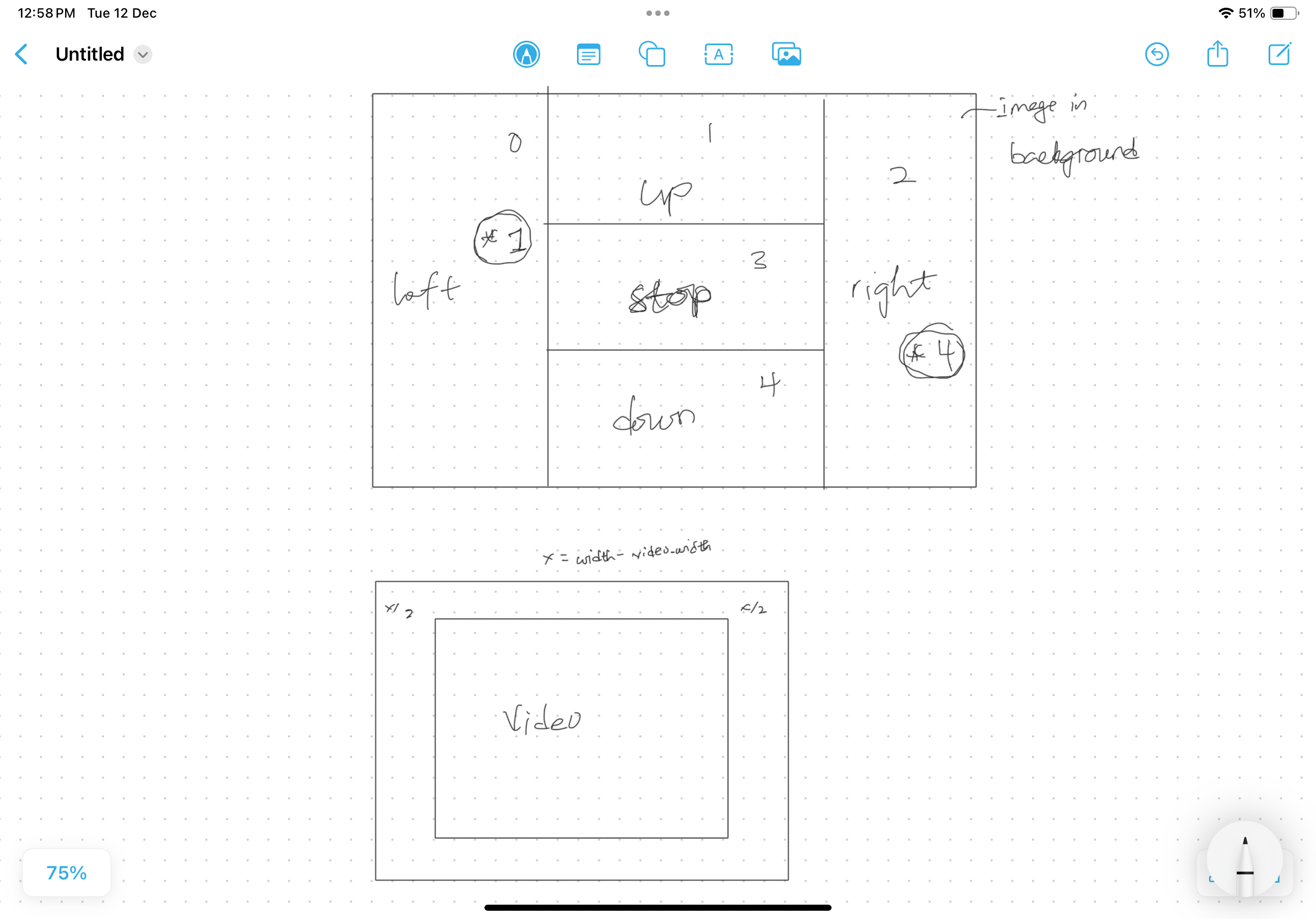
Leveraging the handpose model from ml5.js, the implementation of gesture recognition unfolded by identifying 21 keypoints on a hand. The model, confined to recognizing one hand at a time, prompted the division of the video feed into segments, each corresponding to a distinct direction of motion. The chosen gestures prioritize intuitive and natural user interactions.

Interaction Design

User interaction revolves around using hand movements captured by a webcam, transforming them into navigational commands for the robot. An onboard button toggles the robot’s state, turning it on or off. Although the current iteration lacks auditory feedback, prospective enhancements will explore the integration of sound cues. The unique motion of the robot necessitates users to rely on intuition, adding an element of engagement.

Technical Implementation

The interaction between the p5.js sketch and the Arduino board relies on tethered serial communication, facilitated by the p5.web-serial.js library. A singular value is dispatched from p5 to Arduino, intricately mapped to specific motion sets.

p5.js sketch:

preload():

function preload() {
  
  instructionPage = loadImage('instructions.png');
  
  for (let i = 1; i <= carNum; i++) {
    carArray.push(new Sprite(spriteWidth, spriteHeight, 160, 80));
    carArray[i - 1].x = 80 + i * 20;
    carArray[i - 1].y = 100 * i;
    carArray[i - 1].spriteSheet = 'spritesheet.png';
    carArray[i - 1].anis.offset.x = 5;
    carArray[i - 1].anis.frameDelay = 8;

    carArray[i - 1].addAnis({
      move: { row: 0, frames: 16 },
    });
    carArray[i - 1].changeAni('move');
    carArray[i - 1].layer = 2;
    carArray[i - 1].visible = false;
  }
}

The preload() function loads the instruction page image and initializes an array of car sprites.

setup():

function setup() {
  createCanvas(windowWidth, windowHeight);
  video = createCapture(VIDEO);
  video.size(width, height);

  handpose = ml5.handpose(video, modelReady);
  handpose.on("predict", results => {
    predictions = results;
  });

  video.hide();
}

The setup() function serves as the initial configuration for the canvas, video capture, and the Handpose model. It establishes the canvas size based on the current window dimensions and initializes the necessary components, such as the video capture object and Handpose model. The modelReady callback function is triggered when the Handpose model is prepared for use, ensuring that the application is ready to detect hand poses accurately.

draw():

function draw() {
  background(255);

  flippedVideo = ml5.flipImage(video);

  // Calculate the aspect ratios for video and canvas
  videoAspectRatio = video.width / video.height;
  canvasAspectRatio = width / height;


  // Adjust video dimensions based on aspect ratios
  if (canvasAspectRatio > videoAspectRatio) {
    videoWidth = width;
    videoHeight = width / videoAspectRatio;
  } else {
    videoWidth = height * videoAspectRatio;
    videoHeight = height;
  }

  // Calculate video position
  video_x = (width - videoWidth) / 2;
  video_y = (height - videoHeight) / 2;

  if (currentPage == 1) {
    // display instructions page
    image(instructionPage, 0, 0, width, height);
  }
  else if (currentPage == 2) {
    // serial connection page
    if (!serialActive) {
      runSerialPage();
    } 

    else {
      // hides car animation
      for (let i = 0; i < carNum; i++) {
        carArray[i].visible = false;
      }

      // controlling page
      if (controlState) {
        runControllingPage();
      } 

      // device has been turned off
      else {
        runTorqueyOff();
      }
    }
  }
}

Within the draw() function, various elements contribute to the overall functionality of the sketch. The calculation of video and canvas aspect ratios ensures that the video feed maintains its proportions when displayed on the canvas. This responsiveness allows the application to adapt seamlessly to different window sizes, providing a consistent and visually appealing user interface.

The draw() function is also responsible for managing different pages within the application. It evaluates the currentPage variable, determining whether to display the instruction page or proceed to pages related to serial connection and hand gesture control. This page-switching behavior is facilitated by the mousePressed function, enabling users to navigate through the application intuitively.

readSerial(data):

function readSerial(data) {

  if (data != null) {
    ////////////////////////////////////
    //READ FROM ARDUINO HERE
    ////////////////////////////////////
    if (int(trim(data)) == maxVoltReading) {
      controlState = true;
    }
    else if (int(trim(data)) == minVoltReading){
      controlState = false;
    }

    //////////////////////////////////
    //SEND TO ARDUINO HERE (handshake)
    //////////////////////////////////
    
    let sendToArduino = value + "\n";
    writeSerial(sendToArduino);
    
    // reset value
    value = defaultState;
  }
}

The readSerial(data) function handles communication with an Arduino device. It interprets incoming data, updates the controlState based on voltage readings, and initiates a handshake with the Arduino. This interaction establishes a connection between the physical device and the digital application, enabling real-time responses to user inputs.

drawKeypoints():

function drawKeypoints() {
  for (let i = 0; i < predictions.length; i += 1) {
    const prediction = predictions[i];
    let area = [0, 0, 0, 0, 0];
    for (let j = 0; j < prediction.landmarks.length; j += 1) {
      const keypoint = prediction.landmarks[j];
      fill(0, 255, 0);
      noStroke();
      let x = map(keypoint[0], 0, 640, 0, videoWidth);
      let y = map(keypoint[1], 0, 480, 0, videoHeight);
      ellipse(x, y, 10, 10);
      
      // count number of trues
      // -- helps to detect the area the detected hand is in
      if (withinLeft(x, y)) {
        area[0] += 1;
      }
      if (withinTopCenter(x, y)) {
        area[1] += 1;
      }
      if (withinRight(x, y)) {
        area[2] += 1;
      }
      if (withinMiddleCenter(x, y)) {
        area[3] += 1;
      }
      if (withinBottomCenter(x, y)) {
        area[4] += 1;
      }
      // end of count
    }
    
    // print index
    for (let i = 0; i < area.length; i += 1) {
      if (area[i] == 21) {
        value = i;
      }
    }
  }
}

The drawKeypoints() function utilizes the Handpose model’s predictions to visualize detected keypoints on the canvas. These keypoints correspond to various landmarks on the hand, and their positions are mapped from the video coordinates to the canvas coordinates. By counting the number of keypoints within specific regions, the function determines the area of the hand’s position. This information is crucial for the application to interpret user gestures and trigger relevant actions.

Robot Movement

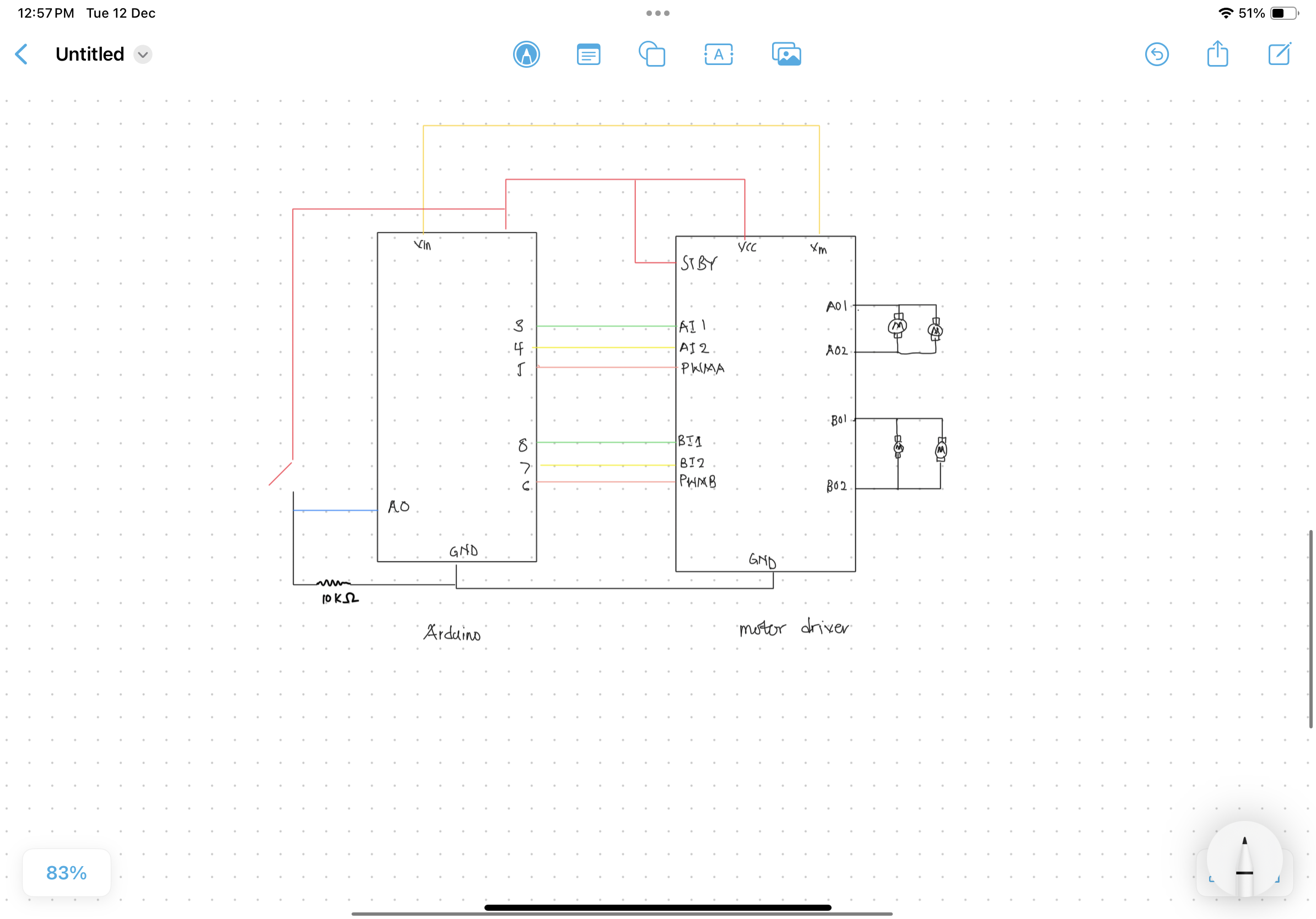
Arduino schematic diagram:

The robot’s movement encompasses pseudo-forward, pseudo-backward, and rotational movements in either direction around its center. Achieving these nuanced movements involved a methodical trial-and-error process, aligning gestures with intended actions.

Arduino sketch

const int ain1Pin = 3;
const int ain2Pin = 4;
const int pwmAPin = 5;

const int bin1Pin = 8;
const int bin2Pin = 7;
const int pwmBPin = 6;

int buttonValue = 0;
int prevButtonValue = 0;
const int defaultState = -1;

const unsigned long eventInterval = 1000;
unsigned long previousTime = 0;

void setup() {
  // Start serial communication so we can send data
  // over the USB connection to our p5js sketch
  Serial.begin(9600);

  pinMode(LED_BUILTIN, OUTPUT);

  pinMode(ain1Pin, OUTPUT);
  pinMode(ain2Pin, OUTPUT);
  pinMode(pwmAPin, OUTPUT); // not needed really

  pinMode(bin1Pin, OUTPUT);
  pinMode(bin2Pin, OUTPUT);
  pinMode(pwmBPin, OUTPUT); // not needed really

  // TEST BEGIN
  // turn in one direction, full speed
  analogWrite(pwmAPin, 255);
  analogWrite(pwmBPin, 255);
  digitalWrite(ain1Pin, HIGH);
  digitalWrite(ain2Pin, LOW);
  digitalWrite(bin1Pin, HIGH);
  digitalWrite(bin2Pin, LOW);

  // stay here for a second
  delay(1000);

  // slow down
  int speed = 255;
  while (speed--) {
    analogWrite(pwmAPin, speed);
    analogWrite(pwmBPin, speed);
    delay(20);
  }

  // TEST END

  buttonValue = analogRead(A0);
  prevButtonValue = buttonValue;

  // start the handshake
  while (Serial.available() <= 0) {
    digitalWrite(LED_BUILTIN, HIGH); // on/blink while waiting for serial data
    Serial.println(buttonValue); // send a starting message
    delay(50);            // wait 1/3 second
    digitalWrite(LED_BUILTIN, LOW);
    delay(50);
  }

}

void loop() {

   /* Updates frequently */
  unsigned long currentTime = millis();
  /* This is the event */
  if (currentTime - previousTime >= eventInterval) {
    /* Event code */
    buttonValue = analogRead(A0);
    
   /* Update the timing for the next time around */
    previousTime = currentTime;
  }

  while (Serial.available()) {
    // sends state data to p5
    if (buttonValue != prevButtonValue) {
      prevButtonValue = buttonValue;
      Serial.println(buttonValue);
    }
    else {
      Serial.println(defaultState);
    }
    
    // led on while receiving data
    digitalWrite(LED_BUILTIN, HIGH); 

    // gets value from p5
    int value = Serial.parseInt();

    // changes brightness of the led
    if (Serial.read() == '\n' && buttonValue == 1023) {
      
      if (value == 0) {
        // 0
        digitalWrite(ain1Pin, HIGH);
        digitalWrite(ain2Pin, LOW);
        digitalWrite(bin1Pin, LOW);
        digitalWrite(bin2Pin, HIGH);

        analogWrite(pwmAPin, 255);
        analogWrite(pwmBPin, 255);
        // 0

      }

      else if (value == 1) {
        // 1
        digitalWrite(ain1Pin, HIGH);
        digitalWrite(ain2Pin, LOW);
        digitalWrite(bin1Pin, HIGH);
        digitalWrite(bin2Pin, LOW);

        analogWrite(pwmAPin, 255);
        analogWrite(pwmBPin, 255);
        // 1
      }

      else if (value == 2){
        // 2
        digitalWrite(ain1Pin, LOW);
        digitalWrite(ain2Pin, HIGH);
        digitalWrite(bin1Pin, HIGH);
        digitalWrite(bin2Pin, LOW);

        analogWrite(pwmAPin, 255);
        analogWrite(pwmBPin, 255);
        // 2
      }

      else if (value == 3) {
        analogWrite(pwmAPin, 0);
        analogWrite(pwmBPin, 0);
      }

      else if (value == 4) {
        // 4
        digitalWrite(ain1Pin, LOW);
        digitalWrite(ain2Pin, HIGH);
        digitalWrite(bin1Pin, LOW);
        digitalWrite(bin2Pin, HIGH);

        analogWrite(pwmAPin, 255);
        analogWrite(pwmBPin, 255);
        // 4
      }

      else {
        analogWrite(pwmAPin, 0);
        analogWrite(pwmBPin, 0);
      }
    }
  }
  // led off at end of reading
  digitalWrite(LED_BUILTIN, LOW);
}

The setup() function initializes serial communication, configures pins, and performs an initial motor test. Additionally, it sends the initial buttonValue to the p5.js sketch for the handshake.

The loop() function checks if the eventInterval has elapsed and updates the buttonValue accordingly. It handles incoming serial data from the p5.js sketch, sending state data back and adjusting LED brightness. Motor control logic is implemented based on the received values from the p5.js sketch, allowing for different motor configurations.

User Experience

End users find the robot’s unconventional design intriguing, coupled with a sense of awe at its mobility. The brief learning curve is accompanied by occasional glitches arising from imperfections in handpose detection, which may result in initial user frustration.

User Testing

IM Showcase

The IM showcase went well overall. Despite a few technical hiccups during the presentation, the feedback from people who interacted with the project was positive. Some issues raised were ones I had anticipated from user testing, and I plan to address them in future versions of the project.

User Interaction 1:

User Interaction 2:

Aesthetics and Design

Crafted predominantly from cardboard, the robot’s casing prioritized rapid prototyping, considering time constraints. The material’s versatility expedited the prototyping process, and the strategic use of zipties and glue ensured durability, with easily replaceable parts mitigating potential damage.

Future Enhancements

Subsequent iterations of ArtfulMotion 2.0 aspire to introduce gesture controls for variable speed, operational modes such as tracking, and exploration of more robust machine learning models beyond the limitations of handpose. The quest for wireless control takes precedence, offering heightened operational flexibility, potentially accompanied by a structural redesign.

Reflection

The completion of this project within constrained timelines marks a journey characterized by swift prototyping, iterative testing, and redesign. Future endeavors shift focus towards refining wireless communication, structural enhancements, and the exploration of advanced machine learning models.

p5 rough sketch:


P5 Sketch

Final Project: RekasBot

Concept:

The idea was to create a bot that can be controlled with hand movement using machine learning with the P5.ml library. The P5 sketch has an in-car design with the steering wheel and the Arduino comprises 4dc motors, two ultrasonic sensors, and some LEDs.

Interactive Design:

For user interactivity, I decided to use the P5.js. The computer video webcam helps the machine learning library to detect the movement of the user’s hand and map these movements to the size of the canvas. This information is used to control the steering wheel, which controls the Arduino.

Arduino Code:

For the Arduino aspect, the motors are controlled using switch cases. The Arduino receives cases from the P5 sketch and based on those cases, the Arduino knows how to control the 4 DC motors. The Arduino uses the ultrasonic sensors to detect obstacles and sends this information to the P5 sketch to be viewed by the user.

#include <Servo.h>//include the Servo library/
#include <time.h>//include the time library for seeding random number

Servo myservo;//creating servo object

const int ain1Pin = 3;//setting pins for motor for left side which is connected in parallel
const int ain2Pin = 4;
const int pwmAPin = 5;

const int bin1Pin = 8;//setting pinf for motor for right side 
const int bin2Pin = 7;
const int pwmBPin = 6;

const int trigPin1 = 11;//setting pins for front ultrasonic sensor
const int echoPin1= A0;//I used A0 pin cause I didnt have space...Please pardon me
const int trigPin2 = 10;//setting pins for back ultrasonic sensor
const int echoPin2 = A1;//here too

const int warningbuzzer=12;//setting the buzzer to 12
//servo motor
const int headmovePin=9;//setting the servo motor pin to 9

int wallstop=0;//initializing the obstacle detection

unsigned long previousMillis = 0;//setting millis to 0
const long interval = 5000;//setting interval for the millis


void setup() {
  myservo.attach(headmovePin);//pass the servo pin to the servo library
  
  randomSeed(time(NULL));//seed random number using the current time 

  pinMode(ain1Pin, OUTPUT);//setting the pins as output and input
  pinMode(2, OUTPUT);//light checker
  pinMode(ain2Pin, OUTPUT);//motor pin
  pinMode(pwmAPin, OUTPUT); // not needed really
  pinMode(bin1Pin, OUTPUT);
  pinMode(bin2Pin, OUTPUT);
  pinMode(pwmBPin, OUTPUT); // not needed really
  // Start serial communication so we can send data
  // over the USB connection to our p5js sketch
  pinMode(trigPin1, OUTPUT);
  pinMode(echoPin1, INPUT);
  pinMode(trigPin2, OUTPUT);
  pinMode(echoPin2, INPUT);
  pinMode(warningbuzzer, OUTPUT);

  Serial.begin(9600);//setting the serial band

  while (!Serial.available()) {
    digitalWrite(LED_BUILTIN, HIGH); // on/blink while waiting for serial data
    Serial.println("0,0"); // send a starting message
    delay(300);            // wait 1/3 second
    digitalWrite(LED_BUILTIN, LOW);
    delay(1000);//delay for a second
  }
}

void loop() {
  wallstop=crushstop();
  //When the serial is detected do this
  while (Serial.available()) {//while the serial connection exists
    digitalWrite(LED_BUILTIN, HIGH); // led on while receiving data
    wallstop=crushstop();//update the wallstop from the crush function
    unsigned long currentMillis = millis();//set current millis

    if (currentMillis - previousMillis >= interval) {
      // save the last time you blinked the LED
      previousMillis = currentMillis;
      movehead();//if the interval is reached, move the head
    }
    int movement = Serial.parseInt();//get the movement case from p5
   if (Serial.read() == '\n') {//when we read a new line,
     switch(movement){//execute the following commmands based on the case
      case 0://no movement
        analogWrite(pwmAPin, 0);
        digitalWrite(ain1Pin, HIGH);
        digitalWrite(ain2Pin, LOW);
        analogWrite(pwmBPin, 0);
        digitalWrite(bin1Pin, LOW);
        digitalWrite(bin2Pin, HIGH);
      break;
      case 1://forward
        analogWrite(pwmAPin, 255);
        digitalWrite(ain1Pin, LOW);
        digitalWrite(ain2Pin, HIGH);
        analogWrite(pwmBPin, 255);
        digitalWrite(bin1Pin, HIGH);
        digitalWrite(bin2Pin, LOW);
      break;
      case 2://reverse
        analogWrite(pwmAPin, 255);
        digitalWrite(ain1Pin, HIGH);
        digitalWrite(ain2Pin, LOW);
        analogWrite(pwmBPin, 255);
        digitalWrite(bin1Pin, LOW);
        digitalWrite(bin2Pin, HIGH);
      break;
      case 3://right front
        analogWrite(pwmBPin, 255);
        digitalWrite(bin1Pin, HIGH);
        digitalWrite(bin2Pin, LOW);
      break;
      case 4://left front
        analogWrite(pwmAPin, 255);
        digitalWrite(ain1Pin, LOW);
        digitalWrite(ain2Pin, HIGH);
      break;
      case 5://right back
       analogWrite(pwmBPin, 255);
        digitalWrite(bin1Pin, LOW);
        digitalWrite(bin2Pin, HIGH);
      break;
      case 6://left back
        analogWrite(pwmAPin, 255);
        digitalWrite(ain1Pin, HIGH);
        digitalWrite(ain2Pin, LOW);
      break;
      default://if not case is gotten within our expected range, stop
        analogWrite(pwmAPin, 0);
        digitalWrite(ain1Pin, HIGH);
        digitalWrite(ain2Pin, LOW);
        analogWrite(pwmBPin, 0);
        digitalWrite(bin1Pin, LOW);
        digitalWrite(bin2Pin, HIGH);
      break;
     }
      delay(5);
      Serial.println(wallstop);//send the detection to p5
      
    }
  }
  
}

int crushstop(){//this function returns 1 when an obstacle is ahead and 2 when an obstacle is behind
  int wallstop=0;//initialize wallstop
  digitalWrite(trigPin1, LOW); 
  delayMicroseconds(2); //basically shooting beems and using the time it takes to bounce back to calculate distance
  digitalWrite(trigPin1, HIGH); 
  delayMicroseconds(10); 
  digitalWrite(trigPin1, LOW); 
  // Time it takes for the pulse to travel back from the object long 
  int duration1 = pulseIn(echoPin1, HIGH); 
  // Universal conversion of time into distance in cm 
  int distance1 = duration1 * 0.034 / 2;//divided by two beause its a two way thing

  digitalWrite(trigPin2, LOW); 
  delayMicroseconds(2); 
  digitalWrite(trigPin2, HIGH); 
  delayMicroseconds(10); 
  digitalWrite(trigPin2, LOW); 
  // Time it takes for the pulse to travel back from the object long 
  int duration2 = pulseIn(echoPin2, HIGH); 
  // Universal conversion of time into distance in cm 
  int distance2 = duration2 * 0.034 / 2;
  if(distance1<5){//if collision is detected behind, send 2
    wallstop=2;
    tone(warningbuzzer,2000);//play the tone
    delay(5);
  }
  else if(distance2<5){
    wallstop=1;//if collision is detected infront, send 1
    tone(warningbuzzer,2000);//play the tone
    delay(5);
  }
  else{
    wallstop=0;
    noTone(warningbuzzer);//if nothing is detected dont play a tone
  }
  return wallstop;//return this info
}

void movehead(){
  myservo.write(random(0, 180));//move the head to a random number between 0 and 180
  delay(15);
}


P5.js:

For this part, the P5.js sketch receives the user hand positions info from the P5.ml library and maps it to get its corresponding points on the canvas. After, these values are averaged and the average-X value is used to control the steer’s left or right turn. The average-Y value is used to control the forward and backward movement. Based on this cases are developed and sent to the Arduino for execution of tasks.

The P5 sketch is divided into five parts

Serial connection:

This part is responsible for connecting the Arduino to the P5 sketch and since its not my code I will not post it

Intro Page:

The next part is the intro page. Is welcomes the user into the project and also gives some info to the user about how to use the vehicle. I made the background picture myself using photoshop and then I added some buttons and sounds

class ipage{
  constructor(IB,S1,S2,F1,F2){//receive all needed variables as in images and sound
    this.BG=IB;//the background
    this.S1=S1;//sound
    this.playbool=false;//boolean to start game
    this.helpbool=false;//boolean to open help page
    this.F2=F2//font
  }
  show(){//this shows the designs in the page
    this.BG.resize(windowWidth,windowHeight);//resize the introimage
    image(this.BG,0,0);//displaying background
    textAlign(CENTER);
    this.createhelp();//calling the help function for the help page
    this.playbox();//calling the playbox button function
    if(this.helpbool){//if the helpbool is true display the help page
      this.helppage();
    }
    return this.playbool;//this returns true if the play button is pressed
  }
  
  playbox(){//this function displays the start button
    rectMode(CORNER);
    fill(150,180,40);
      if(mouseX>windowWidth*0.1&&mouseX<(windowWidth*0.1)+350&&mouseY>windowHeight*0.8&&mouseY<(windowHeight*0.8)+150){
      fill(150,0,0);//creating the hover effect
    }
    if(mouseX>windowWidth*0.1&&mouseX<(windowWidth*0.1)+350&&mouseY>windowHeight*0.8&&mouseY<(windowHeight*0.8)+150&&mouseIsPressed&&!this.helpbool){
      S2.pause();// the play is pressed, play pause the background music
      this.S1.play();//playing the start button pressed sound
      this.playbool=true;//sets the playboolean to true 
    }
    rect(windowWidth*0.1,windowHeight*0.8,350,150,60);//drawing the start button
    fill(0);
    textFont(F1);
    textSize(90);
    textAlign(CENTER);
    text("Start",windowWidth*0.1+180,windowHeight*0.8+110);
  }
  createhelp(){
    fill(100);
    if(dist(mouseX,mouseY,windowWidth*0.9,windowHeight*0.1)<=30){
      fill(60);//create hover effect
    }
    if(dist(mouseX,mouseY,windowWidth*0.9,windowHeight*0.1)<=30&&mouseIsPressed){
      this.helpbool=true;//set boolean to open help page
    }
    circle(windowWidth*0.9,windowHeight*0.1,60);//these following code just creates the help button
    fill(255,255,0);
    textSize(30);
    textFont(NORMAL);
    text("?",windowWidth*0.9,windowHeight*0.1+10);
  }
  helppage(){
    fill(100);
    rect(50,50,windowWidth*0.95,windowHeight*0.9,50);
    textFont(this.F2);
    fill(255);
    textSize(80);
    text('WELCOME',windowWidth*0.5,windowHeight*0.25);
    textSize(30);
    text('Move your Hand Up and Down while pressing the mouse to control the gear',windowWidth*0.5,windowHeight*0.4);
    text('Move your Hand left and right to control the steer',windowWidth*0.5,windowHeight*0.5);
    text('Click on the Q key to go to the Homepage',windowWidth*0.5,windowHeight*0.6);
    text('Press the space bar to connect to Arduino',windowWidth*0.5,windowHeight*0.7);
    text('GOOD LUCK!',windowWidth*0.5,windowHeight*0.8);
    fill(100);
    if(dist(mouseX,mouseY,windowWidth*0.5,windowHeight*0.9)<=30){
      fill(60);//create hover effect
    }
    if(dist(mouseX,mouseY,windowWidth*0.5,windowHeight*0.9)<=30&&mouseIsPressed){
      this.helpbool=false;//set boolean to close help page
    }
    circle(windowWidth*0.5,windowHeight*0.9,60);//these following code just creates the ok button
    fill(255,255,0);
    textSize(30);
    textFont(NORMAL);
    text("OK",windowWidth*0.5,windowHeight*0.9+10);
    
  }
}
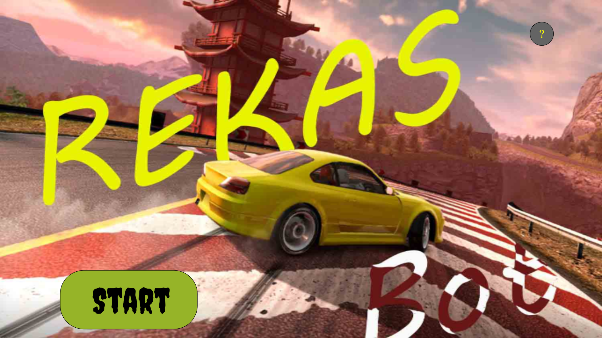
Help Page:

This page is just to give the user info about the game and wish them luck as they embark on the Journey.
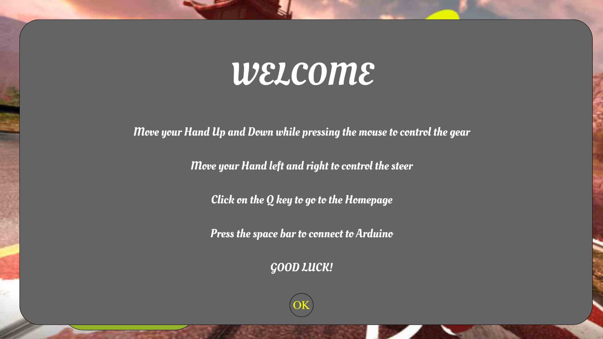
the code is found in the intro class and the page is controlled with the use of Boolean variables.

Dashboard:

Coming into the main page, the Dashboard shows the gearbox and the collision screen that alerts the user when the user is close to an obstacle.

class dash{//this class prints the dashboard, the gear and the detection screen
  constructor(dashY){
    this.Y=dashY;//the Y coordinate to which the dashboard is drawn
    this.movementFB=0;//the front and back movement counter
    this.gearY=0;//this controls the gearmovement
  }
  showdash(){
    push();//creating the dashboard
    strokeWeight(5)//set stroke weight to 5
    fill(193, 154, 107);//fill with brown
    beginShape();//we draw the dashboard
    curveVertex(0,this.Y);
    curveVertex(0,this.Y);
    curveVertex(windowWidth/2,this.Y-50);//creating the curve look
    curveVertex(windowWidth,this.Y);
    curveVertex(windowWidth,windowHeight);
    curveVertex(0,windowHeight);
    curveVertex(0,this.Y);
    curveVertex(0,this.Y);
    endShape();
    pop();
  }
  showgear(gearY){//this function shows the gear
    this.gearY=gearY;//capies value of the gearY from handpose
    rectMode(CENTER);//set rectange mode
    textSize(50);
    fill(0);//fill with black
    rect(windowWidth*0.5,this.Y+110,150,300,50);
    if(mouseIsPressed){//if the mouse is pressed means gear is being controlled
      if(this.gearY<windowHeight*0.35){
        this.movementFB=1;//set gear to drive
      }
      else if(this.gearY>windowHeight*0.5){
        this.movementFB=2;//set gear to reverse
      }
      else{
        this.movementFB=0;//set gear to P
      }
    }
    textAlign(CENTER);//align text to center
    textSize(50);
    fill(0,128,0);//fill with green
    switch(this.movementFB){
      case 0:
        text('P',windowWidth*0.5,this.Y+110);//p for parking
        break;
      case 1:
        text('D',windowWidth*0.5,this.Y+110);//D for drive
        break;
      case 2:
        text('R',windowWidth*0.5,this.Y+110);//R for reverse
        break;
    }
    textAlign(LEFT);
    textSize(12);
    return this.movementFB;//return the gear movement info 
  }
  showScreen(wallstop){//this shows the detection
    rectMode(CENTER);
    textSize(50);
    textAlign(CENTER);
    fill(0);
    rect(windowWidth*0.75,this.Y+110,500,300,50);//create screen
    fill(128,0,0);//fill the text with red
    if(wallstop==1){//if the front ultrasonic sensor is the one sensing
      text('OBJECT',windowWidth*0.75,this.Y+50);
      text('DETECTED',windowWidth*0.75,this.Y+130);
      text('AHEAD',windowWidth*0.75,this.Y+210);
    }
    else if(wallstop==2){//if the back ultrasonic is the one sensing
      text('OBJECT',windowWidth*0.75,this.Y+50);
      text('DETECTED',windowWidth*0.75,this.Y+130);
      text('BEHIND',windowWidth*0.75,this.Y+210);
    }
    else{
      fill(0,128,0);//fill the text with green
      text('No',windowWidth*0.75,this.Y+50);
      text('OBJECT',windowWidth*0.75,this.Y+130);
      text('DETECTED',windowWidth*0.75,this.Y+210);
    }
    textAlign(LEFT);
    textSize(12);
  }
}

In order to show the gear box info it gets info from the poseNet calculations done in the sketch and for the collision screen it uses info from the ultrasonic sensors.
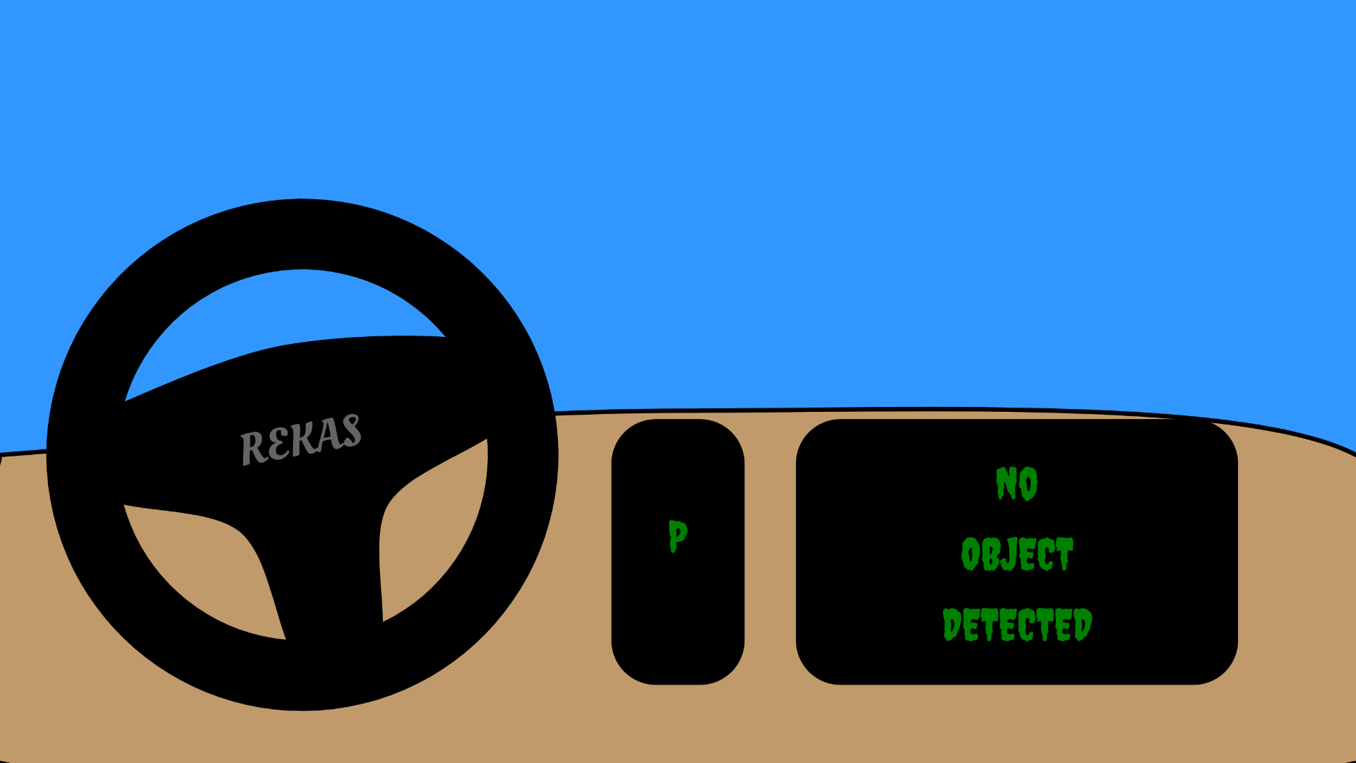
The Steering wheel:

Though also part of the Dashboard, this is a separate class because it  controls the left and right movement using info from the other parts. That is, is uses info from the gear box and collision screen. It is not a picture downloaded from somewhere but a hand coded diagram.

class Steer{//this class creates the steer and controls the car movement front and back
  constructor(ctr,F2,X=windowWidth/3,Y=windowHeight/2){//takes the steerX,the font and the position for the steer to be placed
    this.angle=0;//equate the angle to 0
    this.X=X;//set the X and Y for the placement of the steering wheel
    this.Y=Y;
    this.ctr=ctr;
    this.movementLR=0;//create this Left right variable to store the movement
    this.F2=F2;
  }
  show(ctr){//takes steer x
    this.ctr=ctr;//update the ctr with steerX
  push();//designing the steering using stack so that it can be rotated entirely at once
  translate(this.X,this.Y);//making the orijin these
  rotate(this.angle);//causes the rotation
  noFill(0);
  strokeWeight(80);
  rectMode(CENTER);
  circle(0,0,500);
  fill(0);
  stroke(0);
  strokeWeight(12);
  beginShape();
  curveVertex(-230,-80);
  curveVertex(-230,-80);
  curveVertex(0,-120);
  curveVertex(230,-80);
  curveVertex(230,0);
  curveVertex(80,70);
  curveVertex(40,230);
  curveVertex(-40,230);
  curveVertex(-80,70);
  curveVertex(-230,0);
  curveVertex(-230,-80);
  curveVertex(-230,-80);
  fill(0);
  endShape();
  fill(100);
    noStroke()
  textSize(50)
    textAlign(CENTER);
  textFont(this.F2);
  text('REKAS',0,0);//steering wheel/car brand
  pop();
    if(this.ctr>0&&this.ctr<windowWidth){//while the value is within our range
  this.angle=map(this.ctr,0,windowWidth,-PI/2,PI/2);//update angle based on this
  }
  }
  steerTurn(movementFB,wallstop){//this function controls the turning of the steer
    if(this.angle<-PI/7.5&&movementFB==1&&wallstop!=1){
        this.movementLR=4;//front left
      }
      else if(this.angle<-PI/7.5&&movementFB==2&&wallstop!=2){
        this.movementLR=6;//back left
      }
      else if(this.angle>=-PI/7.5&&this.angle<-PI/8){
        this.movementLR=0;//to prevent bugs 
      }
      else if(this.angle>=-PI/7&&this.angle<PI/8&&movementFB==1&&wallstop!=1){
        this.movementLR=1;//move straight ahead
      }
      else if(this.angle>=-PI/7&&this.angle<PI/7&&movementFB==2&&wallstop!=2){
        this.movementLR=2;//reverse
      }
      else if(this.angle>=PI/7&&this.angle<PI/5){
        this.movementLR=0;//yeah
      }
      else if(this.angle>=PI/5&&movementFB==1&&wallstop!=1){
        this.movementLR=3;//front right
      }
      else if(this.angle>=PI/5&&movementFB==2&&wallstop!=2){
        this.movementLR=5;//back right
      }
      else{
        this.movementLR=0;//dont move
      }
    return this.movementLR;
  }
}

Sketch:

This is the last part that kind of sums everything up. This is where all the other components come together to produce this artwork. This is also where the poseNet functions and full screen Functions are declared.

let mySteer;//variable going to store steer object
let myDash;//gonna store the dashboard object
let handpose;//gonna store posenet object
let video;//gonna store video object
let predictions = [];//gonna store set of predictions from posenet
let steerX=300;//gonna store the average x coordinate of the hand
let gearY=250;//gonna store the average y coordinate of the hand
let movementLR=0;//gonnna store the left and right movement
let movementFB=0;//gonna store the front and back movement

let wallstop=0;//gonna store the obstacle detection
let steercontrol=0;//gonna control steer to make it feel smooth

let IntroBackground;//intropage background
let S1;//sound 1(button)
let S2;//sound 2
let F1;
let F2;
let introp;//gonna store intropage object
let introbool=true;//going to control the intropage display
let gamebool=false;//going to control the mainpage display

function preload(){
  //in this preload function we will load all the uploads we need before we even start the game.
  IntroBackground=loadImage("intro1.jpg");//this is for the background
  S1=loadSound("button.mp3");//these sets are for the sounds
  S2=loadSound("msound.mp3");
  F1=loadFont("font1.ttf");//these sets are for the fonts 
  F2=loadFont("font2.ttf");
  
}

function setup() {
  createCanvas(windowWidth, windowHeight);
  video = createCapture(VIDEO);//capture video using camera
  video.size(width, height);//set the size of the video to that of the screen
   steercontrol=windowWidth/2//set the steercontrol for smoothness
  handpose = ml5.handpose(video);//get posenet from the video feed using the ml library

  // This sets up an event that fills the global variable "predictions"
  // with an array every time new hand poses are detected
  handpose.on("predict", results => {
    predictions = results;
  });

  // Hide the video element, and just show the canvas
  video.hide();
  introp=new ipage(IntroBackground,S1,S2,F1,F2);//create intropage object
  mySteer=new Steer(steerX,F2,windowWidth*0.5,windowHeight*0.85);//create steer object
  myDash=new dash(windowHeight*0.85);//create dashboard object
  S2.loop();//start playing the sound but with loop property
}

function draw() {
  if(introbool){//if the introbool is true show intropage
    gamebool=introp.show();//update gamebool from intro.show function
    if(gamebool){introbool=false;}//if the gamebool is true,set intro to false
  }
  else{
    background(50,150,255);
  myDash.showdash()//show the dash
  drawKeypoints();//call this function for geting info from the video hand detection
  movementFB=myDash.showgear(gearY);//update the front back movement from the showgear function
  movementLR=mySteer.steerTurn(movementFB,wallstop);//update the leftright movement from the steerturn function
  if(steerX>0&&steerX<windowWidth){//if the steerX is within the range we want
    mySteer.show(steerX);//show the steer with this value
    steercontrol=steerX;//update the steercontrol incase we stop getting data
  }
  else{//if the steerX is not in our range,
    if(steercontrol<windowWidth/2-5){steercontrol+=10;}//using our steercontrol,slowly move the steer to the center
    else if(steercontrol>windowWidth/2+5){steercontrol-=10;}
    mySteer.show(steercontrol);
  }
  myDash.showScreen(wallstop);//show the screen with the wallstop getten form the Arduino
  }
}
function keyPressed() {//if spaebar is pressed connect to arduino
  if (key == " ") {
    // important to have in order to start the serial connection!!
    setUpSerial();//connect to arduino
  }
}
function readSerial(data) {
  

  if (data!=null){//if the data is not null
    //////////////////////////////////
    //READ FROM ARDUINO HERE (handshake)
    //////////////////////////////////
    wallstop= int(trim(data));
    //////////////////////////////////
    //SEND TO ARDUINO HERE (handshake)
    //////////////////////////////////
    let sendToArduino = movementLR + "\n";
    writeSerial(sendToArduino);
  }
    
}
function drawKeypoints() {
  let totalX=0;//set variable to store the sum of the x coordinates of all the predictions
  let totalY=0;//same for y
  let avgctr=0;//set a counter to count the predictions
  let len=0;//I dont use len here but i was experimenting somthing
  for (let i = 0; i < predictions.length; i += 1) {
    const prediction = predictions[i];
    len=predictions.lenght*prediction.landmarks.length;
    for (let j = 0; j < prediction.landmarks.length; j += 1) {
      const keypoint = prediction.landmarks[j];
       totalX+=windowWidth-map(keypoint[0],0,video.width,0,windowWidth);//map the points to our window size and sum it
      totalY+=map(keypoint[1],0,video.height,0,windowHeight);
      avgctr++;//increase this too
    }
  }
  steerX=totalX/avgctr;//update steerX with the average of X
  gearY=totalY/avgctr;//same for Y but with average of Y
}
function windowResized() {
  resizeCanvas(windowWidth, windowHeight);//resize the canvas to go to fullpage
}

function keyTyped() {
  // $$$ For some reason on Chrome/Mac you may have to press f twice to toggle. Works correctly on Firefox/Mac
  if (key === 'f') {
    toggleFullscreen();//if f is pressed, show fullpage
  }
  if(key==='q'){//if q is pressed go to h=intro page
    if(introbool==false){
      introbool=true;
      introp.playbool=false;
      S2.play();
    }
  }
  // uncomment to prevent any default behavior
  // return false;
}

// Toggle fullscreen state. Must be called in response
// to a user event (i.e. keyboard, mouse click)
function toggleFullscreen() {
  let fs = fullscreen(); // Get the current state
  fullscreen(!fs); // Flip it!
}

Rekas Bot:

My inspiration for this project comes from my zeal to use the ml library in p5 and I had fun developing this.

Model:
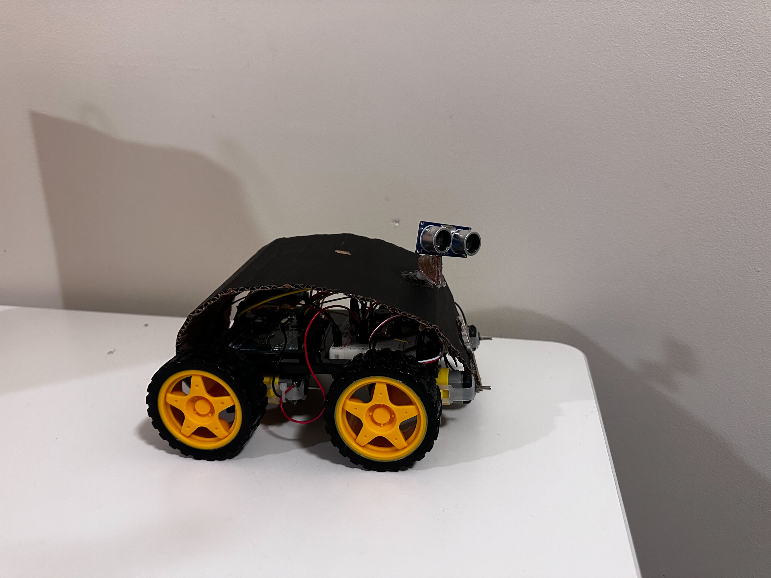
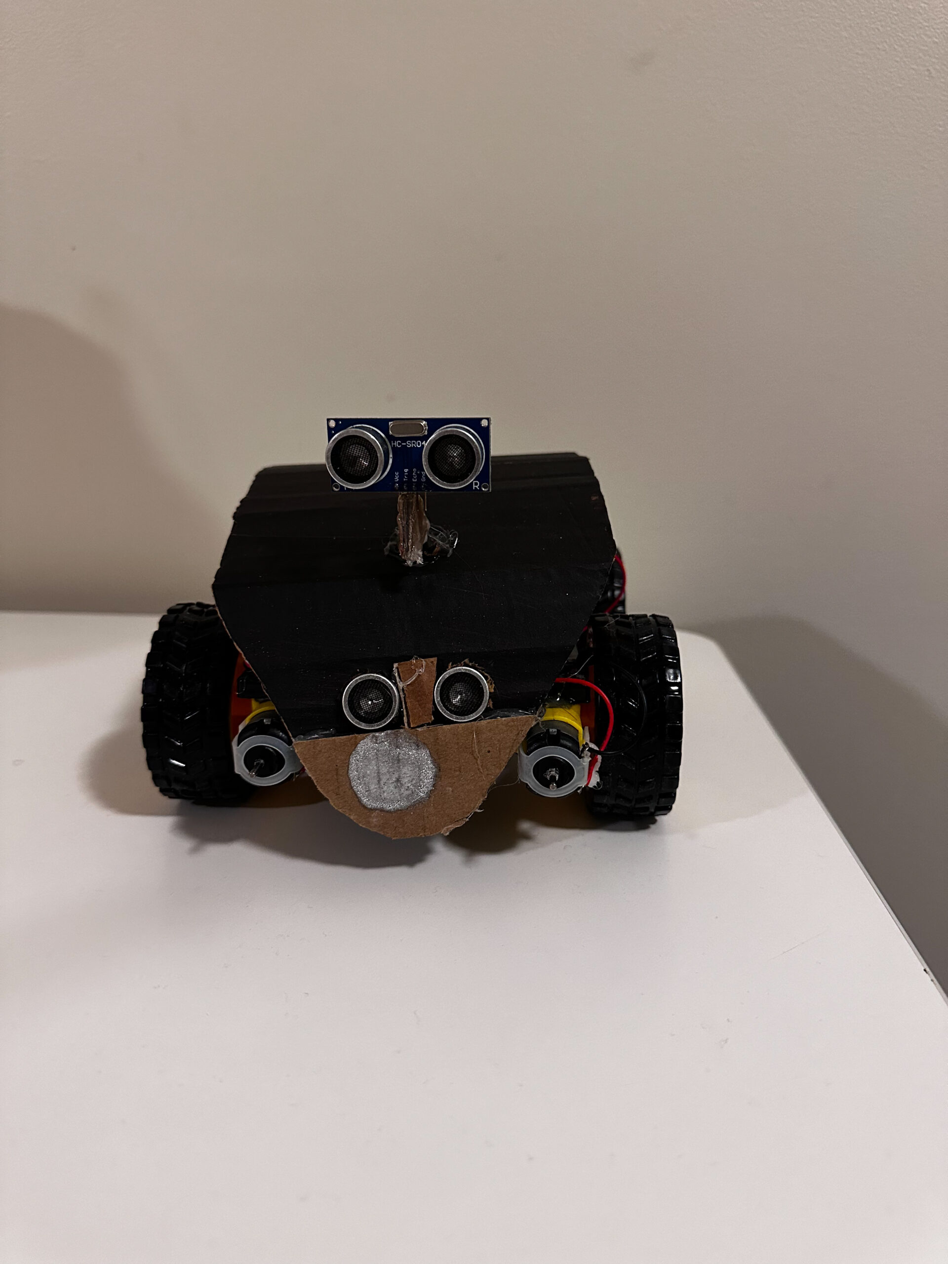
Test Video:

Arduino Circuit Diagram:
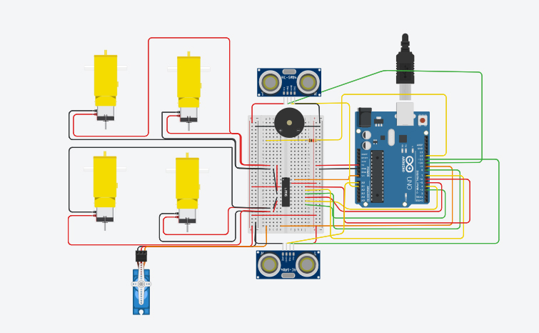
Schematic Diagram:
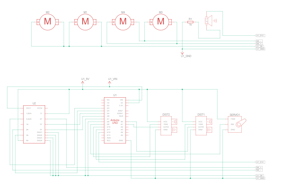
Clarification on the Schematic motor drawing:
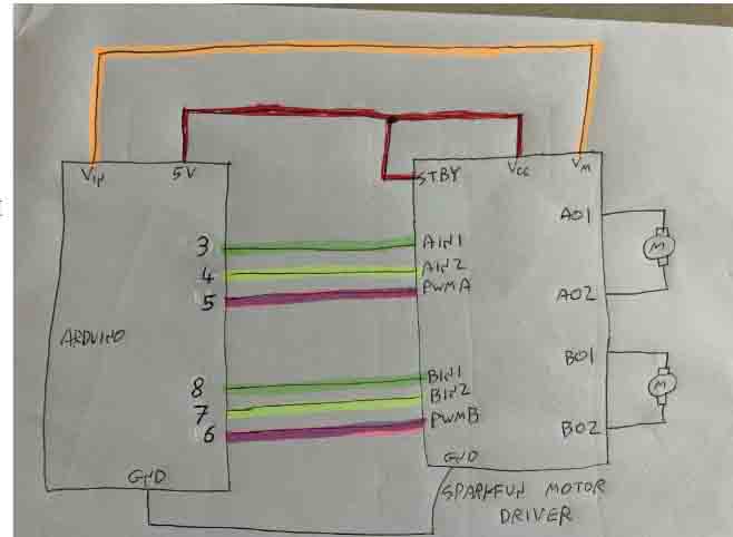
By Aya Riad

Future Improvements:

I Tried to implement Bluetooth but I was not able to because it kept on failing even though I had connected and set up everything right so I wish to be able to find a way to make this connection more reliable and also I plan to make the machine learning more reliable in future.


IM Showcase:

So just before the showcase started, I added one line of code which made the bot move randomly as though it had life.

if(introbool){//if the introbool is true show intropage
    gamebool=introp.show();//update gamebool from intro.show function
    movementLR=int(random(0,6));//do random stuff
    if(gamebool){introbool=false;}//if the gamebool is true,set intro to false
  }

I am really proud of this last decision.

and when you  want to drive it, it stops the random movements.

For more videos

Thank you.