
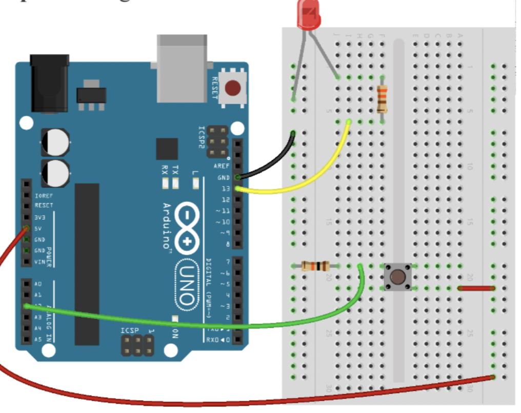
My Arduino code simulates a mini DJ player by incorporating a potentiometer and a switch. The potentiometer, connected to analog input pin A1, emulates a DJ slider or knob, allowing you to control the brightness of an LED connected to PWM pin 11. This provides a visual representation of adjustments such as volume or fading effects.
Meanwhile, the switch, connected to digital input pin A2, mimics a button on the DJ player. When the button is pressed, a yellow light connected to pin 13 is activated briefly, creating a visual cue for a button press or an effect. The code establishes a loop that continuously reads the analog sensor value, and button state, and adjusts LED brightness accordingly, producing a dynamic and interactive simulation of a basic DJ player interface.
It does not look like DJ player in the bright light, and it was hard for me to take a video with one hand and simultaneously press the button with another hand.
int led = 11; //the PMW pin the LED is attached to

void setup(){
  Serial.begin(9600);
  //declare pin 11 to be output:
  pinMode(led,OUTPUT);
  pinMode(13, OUTPUT); //yellow light
  pinMode(A2, INPUT); //button
}
  // put your setup code here, to run once:


void loop() {
  // put your main code here, to run repeatedly:
  int sensorValue = analogRead(A1);
  //Serial.println(sensorValue);

  int buttonState = digitalRead(A2); //button

  Serial.println(buttonState);
  if (buttonState == 1) {
    digitalWrite(13, HIGH);
    delay(100);

  } else {
    digitalWrite(13, LOW);
    //delay(300);
  }


  //set the brightness of pin 11 according to the sensor value/4)
  analogWrite(led, sensorValue/4);

  //wait for 30 milliseconds to see the diming effect
  delay(30);
}
One particularly interesting aspect of the code is the use of the analog input from a potentiometer to control the brightness of an LED. The line int sensorValue = analogRead(A1); reads the analog input from pin A1, representing a DJ slider or knob. The subsequent analogWrite(led, sensorValue/4); adjusts the brightness of an LED on pin 11 based on this input, creating a dynamic and interactive simulation of volume or fade control. This part of the code adds a tangible and intuitive user interface element to the mini DJ player simulation.
(I also refer to the slides from Professor!)