
Approach and Concept:
It took me a long time to come up with the idea for this project given the requirements it had. But at the end of our previous lecture, I realized I could make a night-light+morning alarm system.
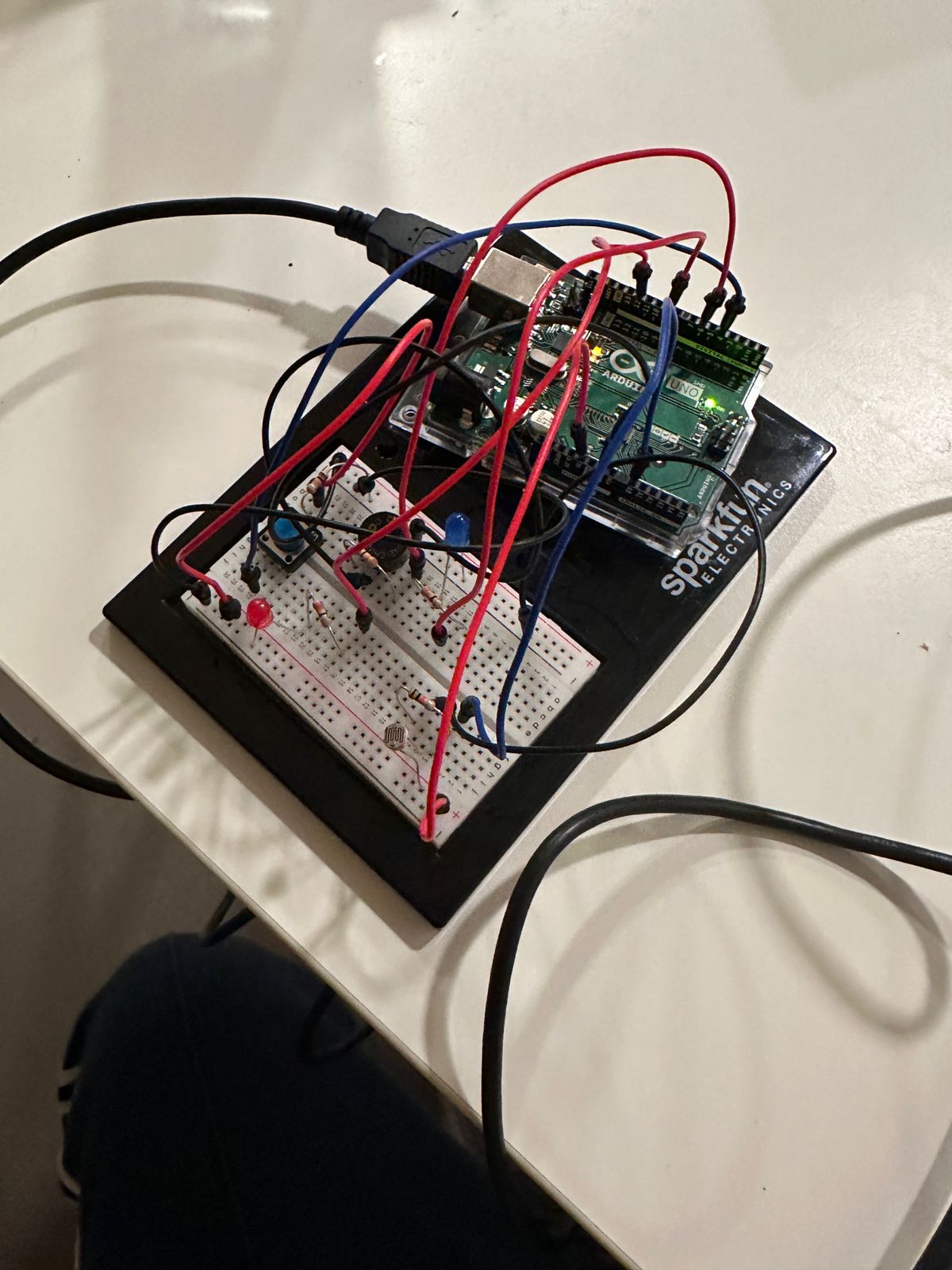
For my analog input I use the light sensor we employed in class. In the morning, this turns on the buzzer (digital output 1) and the red LED light( digital output 2). While it’s night (low light) the blue LED (analog output) blinks in a slow and satisfying manner. A button (digital input switch) can be used to turn the whole system off or on at any given time.
I believe this whole system, if refined further a bit has actual practical utility, and I’m really happy I could make something like this on my own!
Highlights:
I would like to highlight both the coding and the hardware work for this project:
Coding: The system uses a state management system. When I tried to use code from the examples we used in the lecture. This became complicated because doing things like making the analog output led blink slowly couldn’t be done through for loops – or the delay would mess up with the state switching mechanism. To navigate through this, I had to remove the for loops and instead work directly with the loop function. Similarly, I faced this issue again with the buzzer where the delay’s blocking nature was causing some problems – leading me to use the external ezBuzzer library. Beyond this, joining together so many components itself was a fun challenge!
void loop() {
  buzzer.loop();
  // read the state of the pushbutton value:
  buttonState = digitalRead(buttonPin);
  int analogValue = analogRead(A0);
  // check if the pushbutton is pressed. If it is, the buttonState is HIGH:
  if (buttonState == HIGH && led_state==0) {
    while(buttonState==HIGH)
    {
      buttonState = digitalRead(buttonPin);
    // turn LED on:
      led_state=1;
    }
  }
  else if(buttonState == HIGH && led_state==1)
  {
    while(buttonState ==HIGH)
    {
      buttonState = digitalRead(buttonPin);
      led_state=0;
    }
  }
  Serial.println(led_state);
  digitalWrite(ledPin,led_state && led_stateD);
  if(led_state==0 || led_stateD==0)
  {
    if (buzzer.getState() != BUZZER_IDLE) {
      buzzer.stop() ; // stop
    }
  }
  else
  { if (buzzer.getState() == BUZZER_IDLE) {
      int length = sizeof(noteDurations) / sizeof(int);
      buzzer.playMelody(melody, noteDurations, length); // playing
    }
  }
  if (analogValue < 300) {

    led_stateD=0;
    led_stateA=1;
  }
  else {
    led_stateD=1;
    led_stateA=0;
  }
  if(led_state==1 && led_stateA){
  // fade in from min to max in increments of 5 points:
  if(millis()%10==0) {
    // sets the value (range from 0 to 255):
    fadeValue+=increment;
    analogWrite(ledPinAnalog, fadeValue);
    if (fadeValue==255 || fadeValue==0)
      increment*=-1;
  }}
  if(led_state==0 ||led_stateA==0)
    analogWrite(ledPinAnalog, 0);

}
Hardware: The connections itself were simple enough in themselves – since I had knowledge of what we had done in class to borrow from. However, given the many elements the board itself got messy – making navigation a hassle.
Reflections and Future Work:
There are several improvements I would like to make on this work. On the technical implementation aspect, I can possible manage the wires I use much better than I have done here. And on the coding aspect, the code can definitely be made more streamlined and easier to read.
In terms of future work, I would like to add more lights to the nightlight aspect, and make the blinking pattern more complex to have a more soothing experience. Similarly, the buzzer noise and the morning alarms can also be improved aesthetically. In terms of functionality, it would be nice to have another button than can function as a snooze button.