Final – Arduino of Time

Where has the time gone? The semester is nearly over, and Christmas so close. The incomprehensible specter of 2023 peeks around the corner, and I again lament the graying of memories. Yet there is a gift that has been granted unto humanity that can color in even the most ashen of memories: music. For they say that music is the vessel of memory, and memory the muse of music.

Concept & Description

The original concept—an Arduino-powered musical instrument that users can physically interact with to play songs that activate certain effects in p5js—has fortunately withstood the tides of reality! I was also able to write up an overarching mini-narrative of sorts that serves as a framing device that ties the project together and allows for the user to have a more immersive experience.

Explained at the beginning of the p5js sketch before the main game, the premise of the project is that the user plays as an amnesiac who recovers pieces of their memory through 6 songs that are tied to certain memories and emotions of the past. The user is then presented with a list of six songs, with each one having a combination of buttons/notes—playing a song correctly on the Arduino instrument triggers an according scene of remembrance, which is represented by a short video of said memory being played together with a text box.

The project is heavily inspired by the Legend of Zelda video game series, owing to it not just the initial inspiration but also much of the assets. All 6 songs are actual songs from Legend of Zelda: Ocarina of Time, and the aesthetic direction + images and videos are from Legend of Zelda: Breath of the Wild.


Implementation & Highlights

Building upon the progress made in the last post—in which I assembled and coded the Arduino instrument, with the value corresponding to the pressed button/played note being sent to p5js—the next main step was to work on writing code in p5js that 1) gathers and holds on to the data from Arduino and 2) checks if the combination of said incoming data corresponds to one of the six songs 3) plays a number of effects corresponding to the song that has been played (if there is any). The following block of code is the method I used to achieve the first part of this step:

//Method for Collecting Arduino Data//

//Make Array to Gather Notes
const notesArray = [];

function readSerial(data) {
  ////////////////////////////////////
  /////  READ FROM ARDUINO HERE  /////
  ////////////////////////////////////
// Make sure there is actually a message
  if (data != null) {
    let fromArduino = data;
//Reset Array If It's Full (6 Notes)
    if (notesNum >= 6){
      for (i = 0; i < notesNum; i++){
        notesArray.pop();
      }
    }
//Add Played Note to the Array
    notesArray.push(data);
  }
}

As each song is an arrangement of six notes, the array needs to be able to hold onto the notes until it reaches a total of six. If a note is played after the sixth has been recorded, the array is reset to make way for a new combination. When an array is full, the second part of the step is carried out through the following code:

//Song is Stated as Array
const stormsSong = [0, 1, 4, 0, 1, 4];

//Function Used to Compare User Input to Songs
function songCheck(s1, s2){
  return s1.toString() == s2.toString();
}

//The Code Below is in Draw()
//Example: If Song is Played, Effects Activate
if ((songCheck(notesArray, timeSong)) == true){
 if (songPlaying() == false){
 //Audio File Played
  timeAudio.play();
 //Trigger Variable Set to True
  timeTrigger = true;
 }
}
//True Trigger Variable Activates Function Containing Effects
if (timeTrigger == true){
 timeMemory();
}

The function songCheck() uses the .toString() method to convert two chosen arrays into two string objects, which it then uses to compare and return whether the two are the same. As demonstrated in the example, an if() loop containing this function is used to compare notesArray with one of the six preexisting songs, which are also arrays (in this case, timeSong, an array for the Song of Time)—and if the song played on the Arduino instrument matches the song, a set of effects corresponding to the song are played.

A little explanation on the “effects”: playing each tune triggers an audio file from Ocarina of Time of the in-game ocarina playing said tune (this is prompted by the timeAudio.play() line of code), a video or gif of a scene from Breath of the Wild that corresponds with the song (which represents a memory), and a text box above it that contains a short, sentimentally written passage. Playing the Song of Time results in a trigger variable named timeTrigger being set to true, which in turn activates a function named timeMemory that contains the code for the video and text:

//Function Containing Video and Text for Song of Time
function timeMemory(){
//Video is Mapped to Image and Played
  let timeImg = timeVid.get();
  image(timeImg, 0, 0, 960, 540);
  timeVid.play();
//Make Text Box
  tint(255, 150);
  image(memoryBG, 40, 308, 880, 182);
  noTint();
//Write Text; TypeWriter Effect
  fill(185, 159, 102);
  textSize(40);
  let currentString = timeString.substring(0, currentCharacter);
  push();
  text(currentString, pageMargin + 10, 313, width - pageMargin*2, height - pageMargin);
  pop();
  currentCharacter += random(0.3, 0.5);
}

Thus is the general pattern for all 6 of the songs and the overall gameplay loop—each song has an array containing the notes; the tune last played by the user on the Arduino instrument is checked against each song; if there is a match, the effects bound to the song are played; after the song and video has played once, the screen returns back to the scene that shows the songlist; users can then play another song again and see its effects.


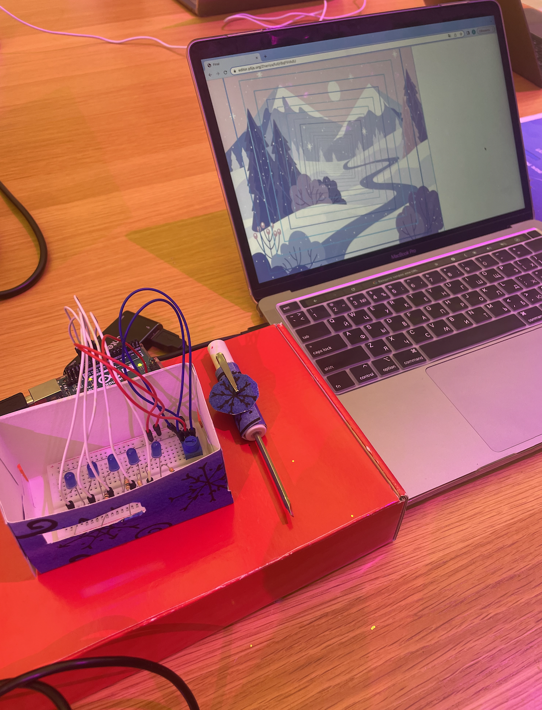
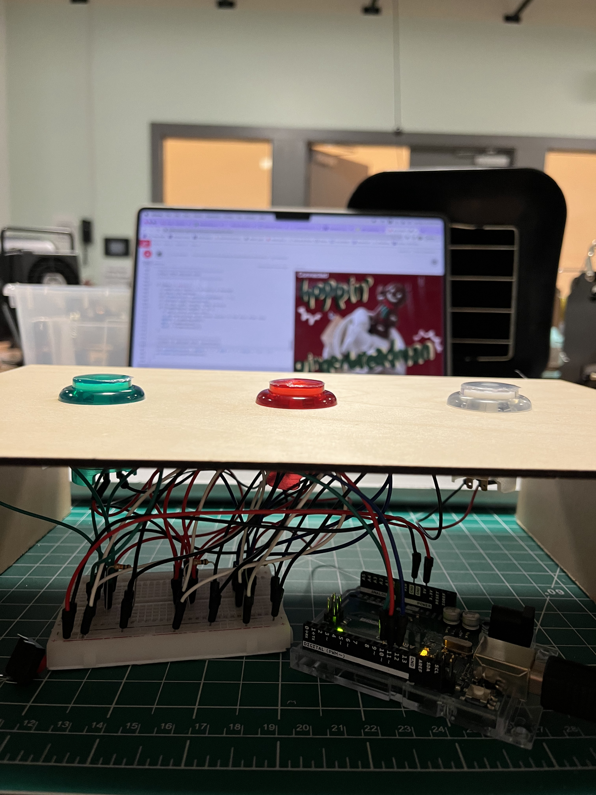
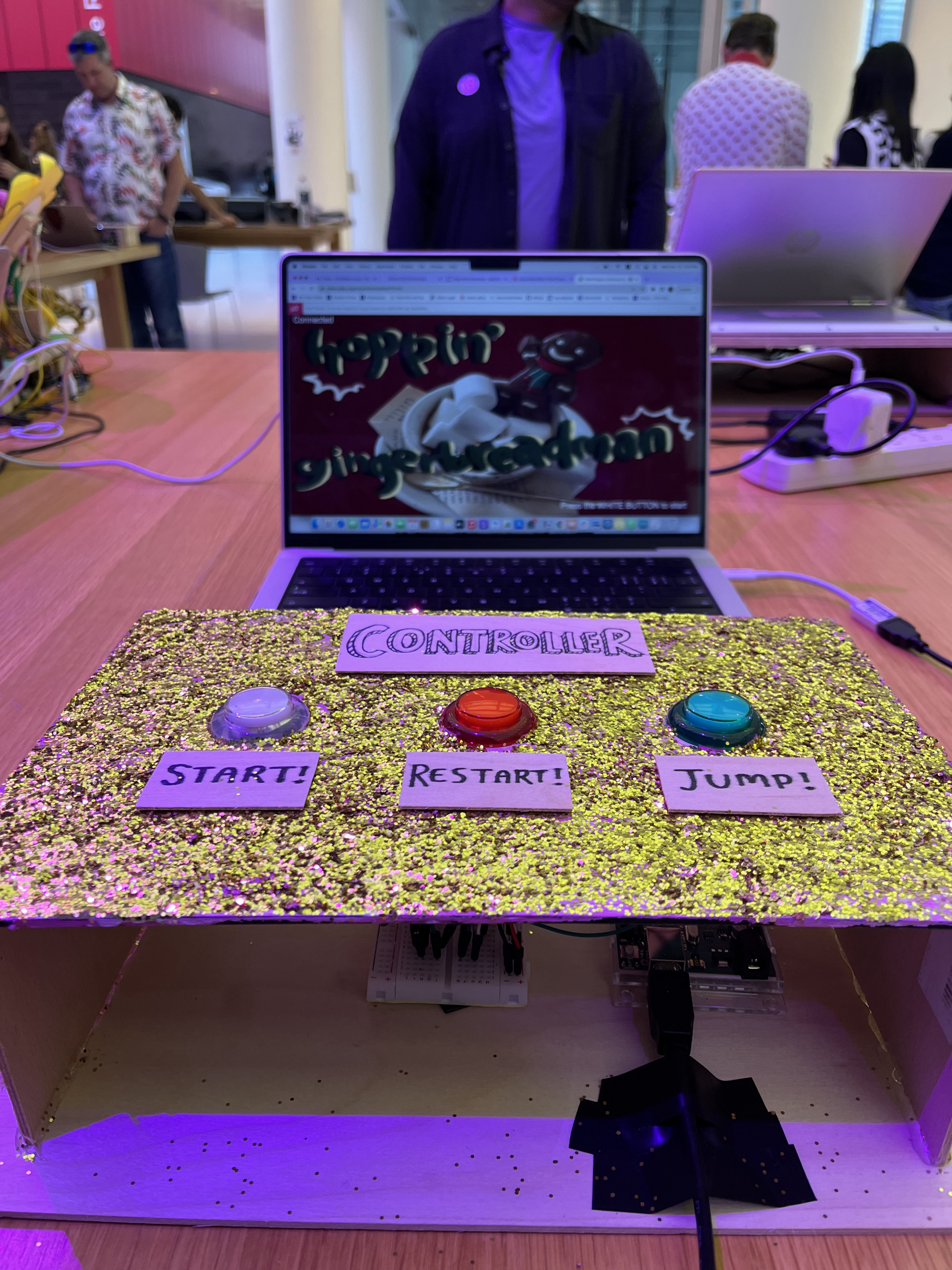
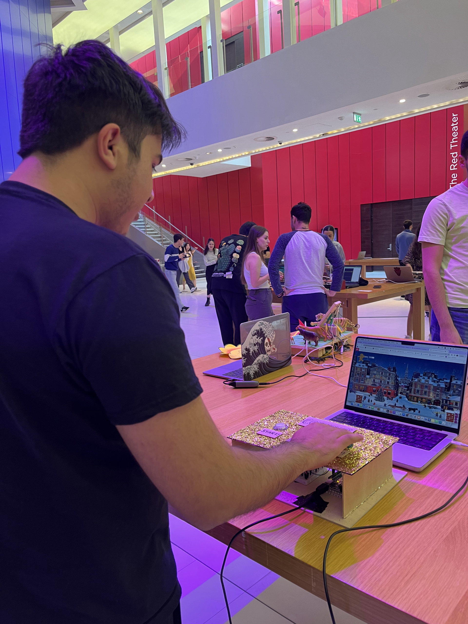
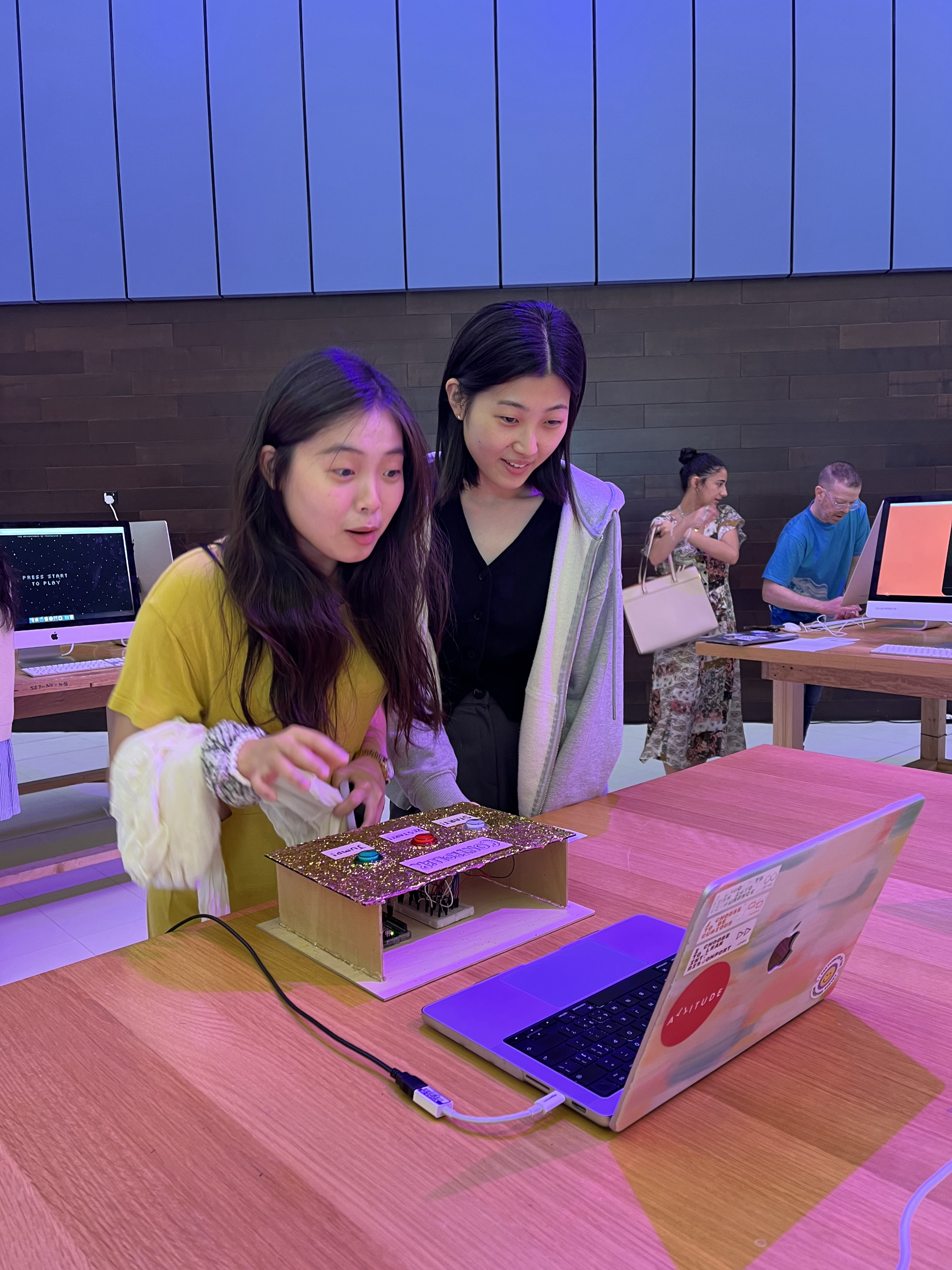
For the physical part of the project, I decided to make a nifty box of a controller-instrument with buttons and a speaker that are connected to the Arduino housed within. With help from the Lab Assistants, I was fortunate enough to be able to use the laser cutter in the IM Lab to acquire six wooden panels (the top panel having five circular holes for the buttons and one rectangular hole for the speaker, and the side panel on the right having a little hole through which the USB cable runs) that I taped together to make a rectangular prism.

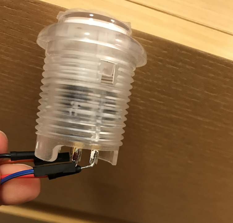
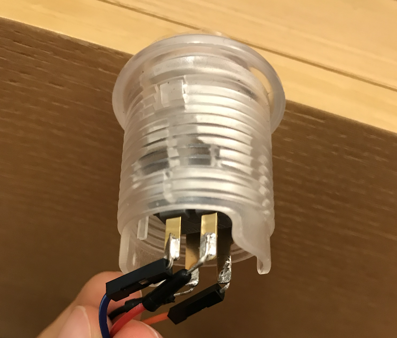
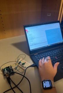
One major step that I was worried about was soldering wires onto the big buttons that I chose to use (they’re so much more satisfying to press than the little ones that come in the kit). Despite having watched Professor Shiloh give a clear demonstration in class, I was nervous about trying my own hand at it. After watching a few tutorials as a refresher, I booted on the soldering station and clenched the iron in my hand—and to my surprise, it came rather easily! By the time I was soldering the wires onto the fifth and last button, I felt that I had gotten the hang of it and was somewhat successful at making the drops look nice and neat.

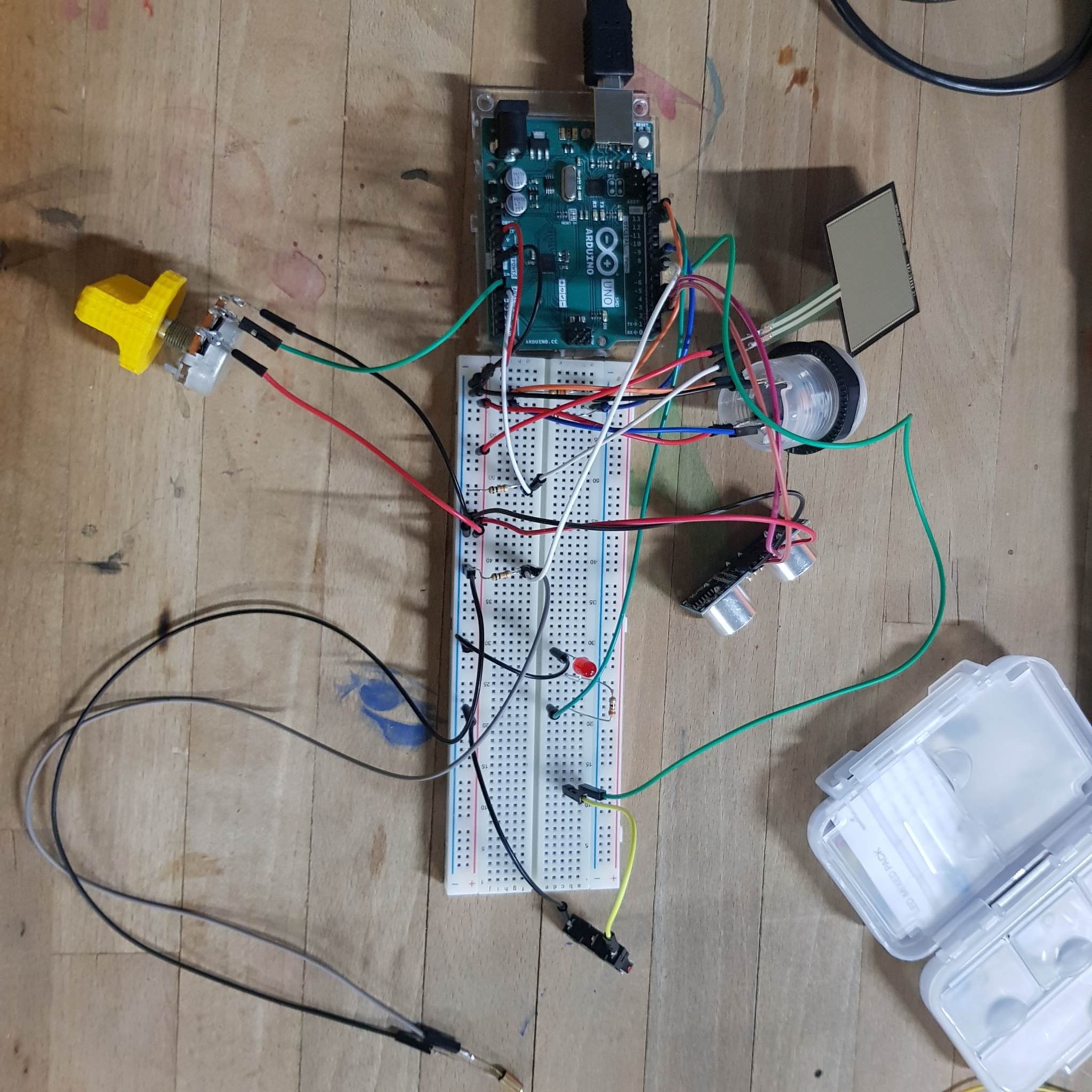
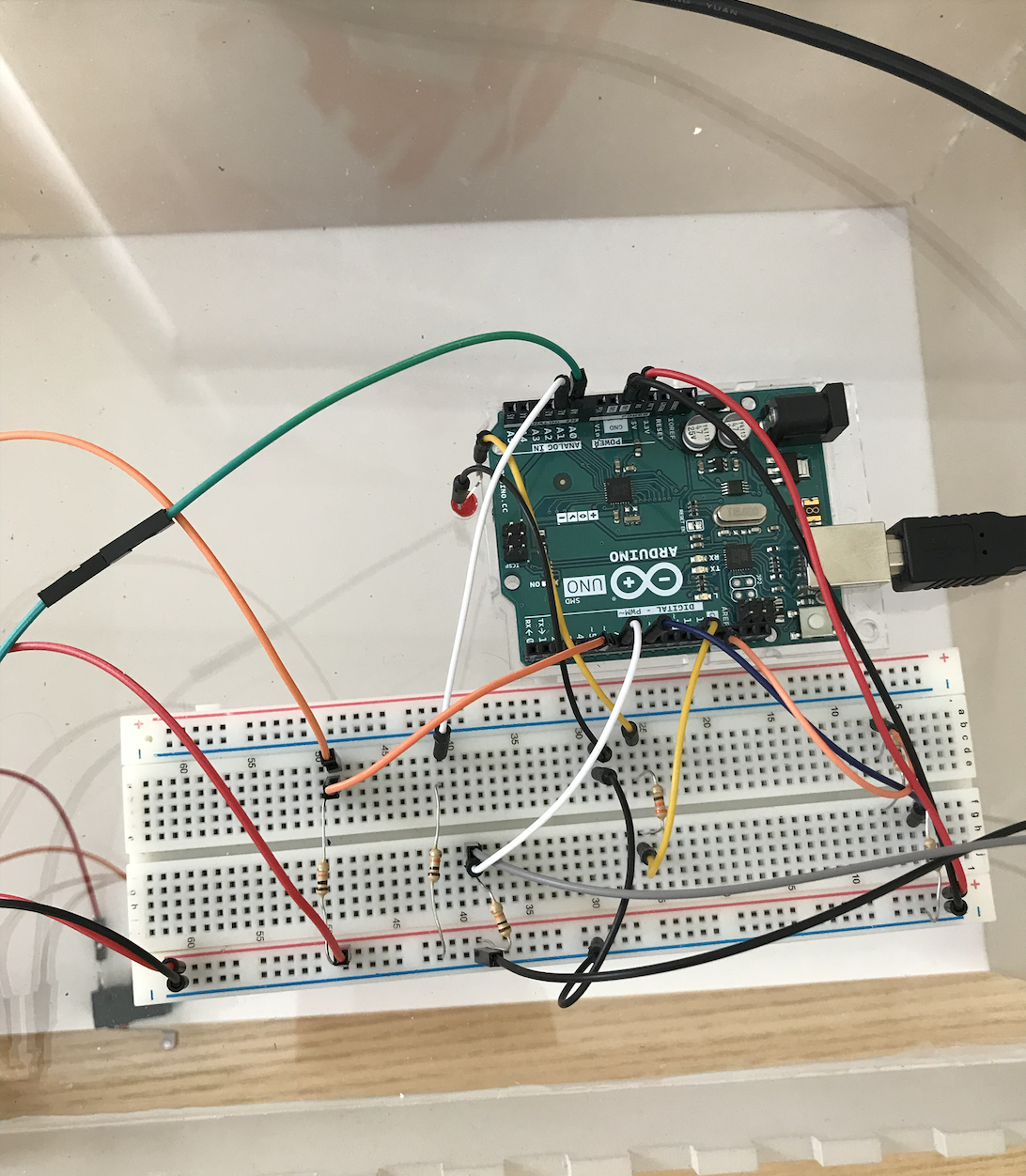
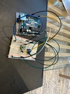
With the buttons all wired up and the wooden box complete, I was ready to assemble my controller-instrument. The original circuit looked like this:

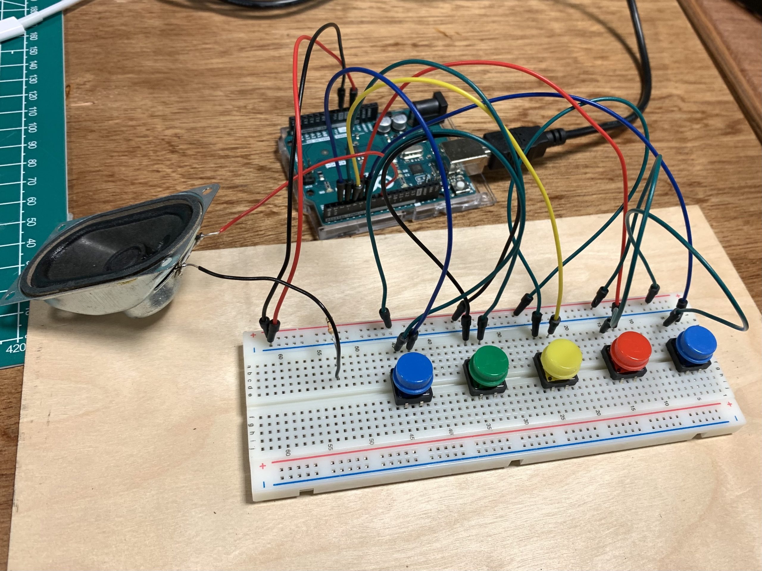
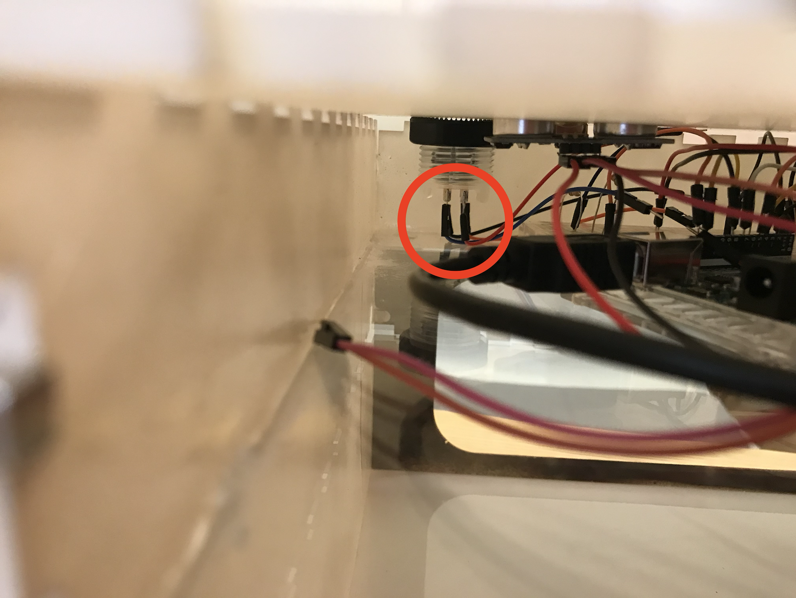
Placing the Arduino and breadboard inside the box, I carefully deconstructed the parts of the circuit that needed to be adjusted and hooked the buttons to the breadboard one by one…and voila!

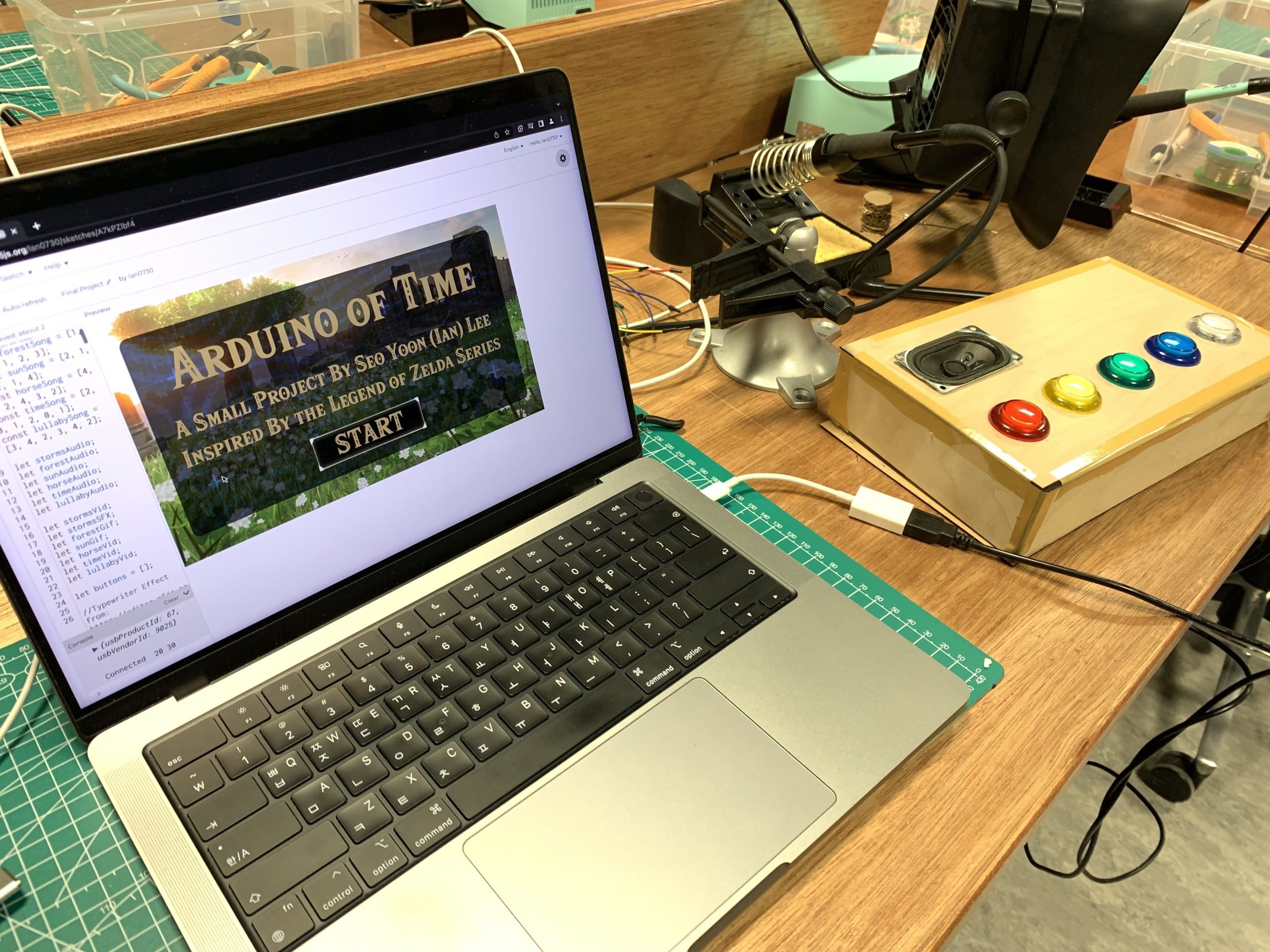
The fabled Arduino of Time.
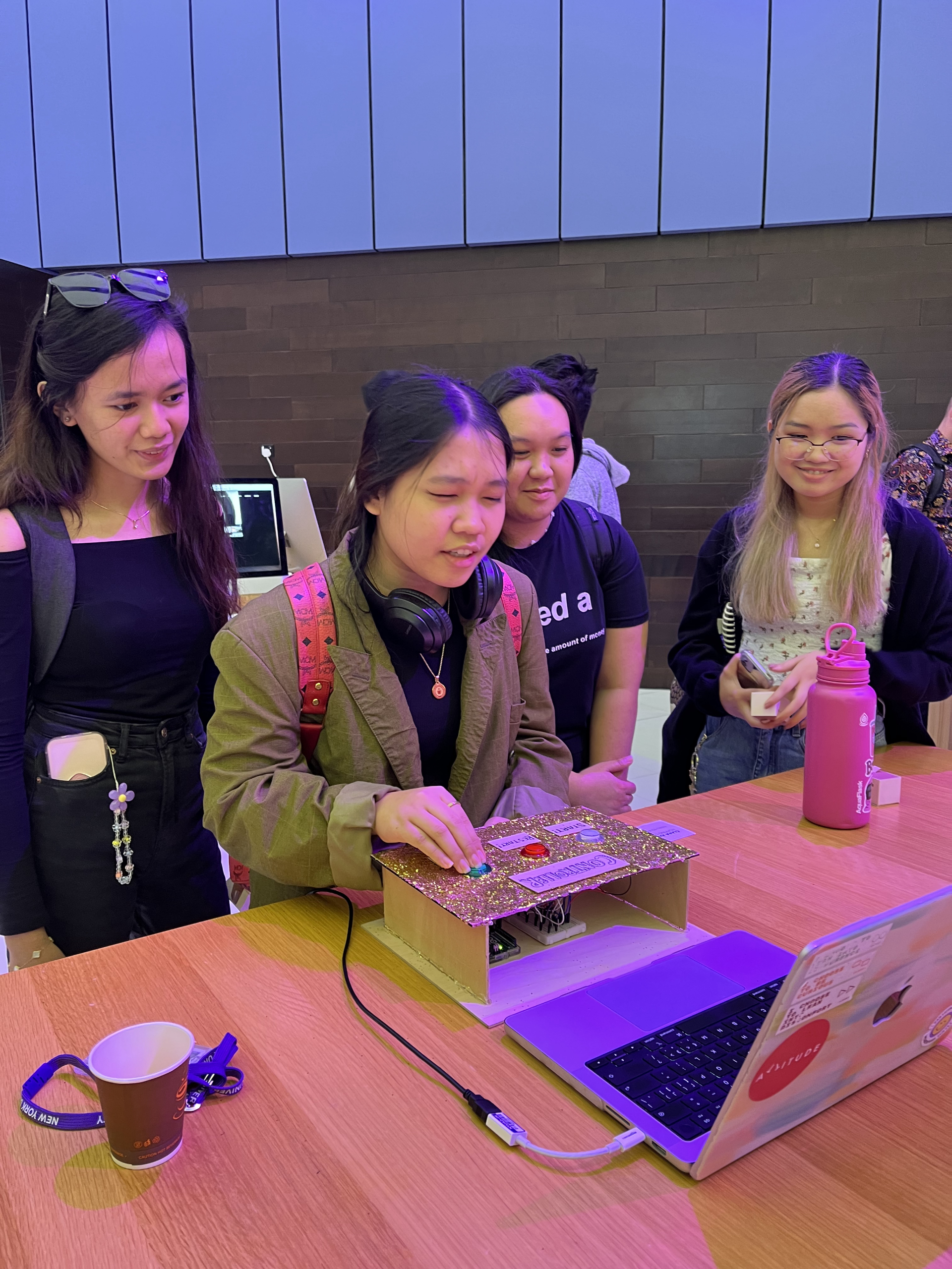
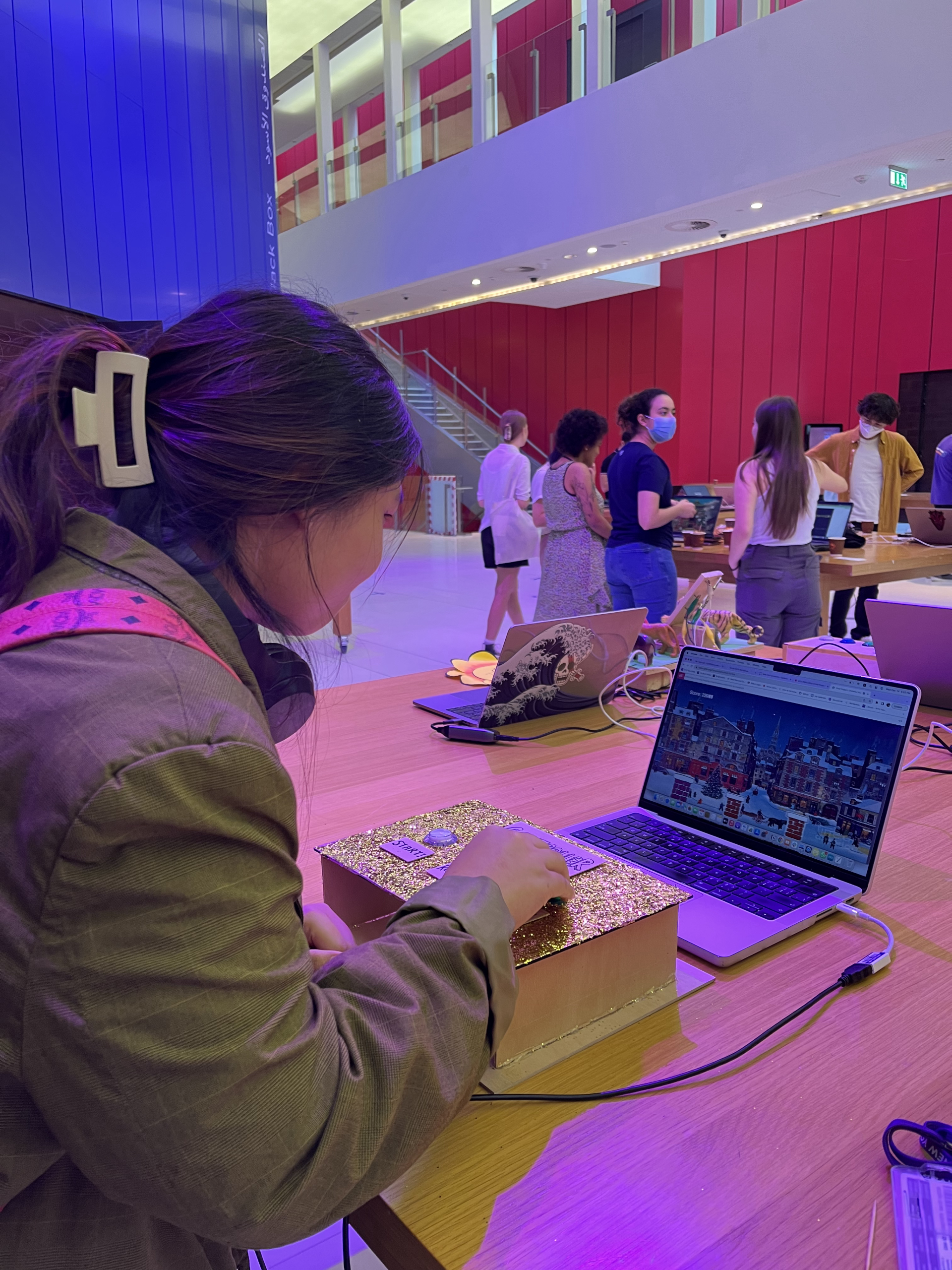

Video Demonstration


Reflections

It’s been an amazing journey, and I’m very proud 0f what I was able to achieve for this final project! I’ve said it time and time again on this blog, but it really is a wondrous experience to fish an idea out of your mind, build upon it, and create something palpable. This course has not only taught me the basics of p5js and Arduino, but also inducted me into the realm of IM thinking—a space that encourages one to act upon creative ideas and engage with them in meaningful ways. And so the semester comes to a close…but I will continue to hold on to what I have learned.

Final Project Documentation

Concept

Link to my user testing video:
https://drive.google.com/file/d/1r4EBRKhNevopUEoBOfhuoM1EDaFciAEV/view?usp=sharing

I created an interactive mini-game based on a fairy tale I heard when I was a child. I was told that at night in winter, Ayaz ata(Santa) and his magical helpers painted on the windows, to delight children in morning . Of course, these “patterns” on the windows do not appear by themselves, but when the weather is very cold, the windows freeze and there is a miracle of nature. Lines and patterns are random, so there are numerous ways to interpret them. To recreate this idea, I used the potentiometer as a basis for random and free drawing- specifically to create the pattern by rotating rectangles. Through the potentiometer, the users will be able to control the rotation angle and feel themselves as a character of my childhood fairytale.
Inspo:

Implementation
The implementation process involves the following steps:
The interaction design involves creating a control interface that allows users to rotate the rectangles in order to create patterns on the window. This interaction will be implemented using a potentiometer, which is connected to an Arduino board.

1. Writing the Arduino code:
The Arduino code is responsible for reading the data from the potentiometer and sending it to the p5.js code. This code sets up the Arduino to use 5 LEDs, each connected to a different pin. It then sets up a loop to turn on each of the LEDs one by one and wait for 200 milliseconds before turning on the next one. It then turns off each of the LEDs in a similar way but with a longer wait time of 300 milliseconds. Finally, it reads an analog value from pin A0, maps it between 0 and 255, and sends it over a serial port.
Final Arduino code:

int LED1 = 13;
int LED2 = 12;
int LED3 = 11;
int LED4 = 10;
int LED5 = 9;

// Arduino Code
void setup() {
Serial.begin(9600);
pinMode(LED1, OUTPUT);
pinMode(LED2, OUTPUT);
pinMode(LED3, OUTPUT);
pinMode(LED4, OUTPUT);
pinMode(LED5, OUTPUT);
}
void loop() {
digitalWrite(LED1, HIGH); // turn on LED1
delay(200); // wait for 200ms
digitalWrite(LED3, HIGH); // turn on LED2
delay(200); // wait for 200ms
digitalWrite(LED2, HIGH); // turn on LED3
delay(200); // wait for 200ms
digitalWrite(LED5, HIGH); // turn on LED3
delay(200);
digitalWrite(LED4, HIGH); // turn on LED3
delay(200);

delay(200);
digitalWrite(LED1, LOW); // turn off LED1
delay(300); // wait for 300ms
digitalWrite(LED3, LOW); // turn off LED2
delay(300); // wait for 300ms
digitalWrite(LED2, LOW); // turn off LED3
delay(300);
digitalWrite(LED5, LOW); // turn off LED3
delay(300);
digitalWrite(LED4, LOW); // turn off LED3
delay(300);
int analogValue = analogRead(A0);
byte byteToSend = map (analogValue, 0, 1023, 0, 255);
Serial.write(byteToSend);
delay(50);
}

2. Writing the p5.js code:
The p5.js code is responsible for drawing the rectangles and rotating them in response to the data received from the Arduino board. Moreover, P5js code included background which had a snowflakes behind the pattern. This code sets up a program that displays a colorful background with snowflakes falling in the background. The pattern is made up of different rectangles with randomly selected colors from a list of colors. The snowflakes are made up of ellipses that move down the screen, with gravity affecting their speed(0, so the overall image is not too messy). To control the angle of rotation, a serial port is used to read real-time data. The size of the snowflakes and the number of layers in which they fall is also configurable.
Final Version of p5js:

3. Communication between Arduino and p5.js:
The communication between the Arduino board and the p5.js code is done via serial communication. The Arduino code sends the data from the potentiometer to the p5.js code, which then uses the data to rotate the rectangles. I also used p5.serial control app, since other methods didn’t really work for me.
Additional:
I decided to create little box and the “wand” for the best experience of the user.Moreover I’ve added LED to my board which created sparkling effect in a little house(box).

Once all of the steps are complete, the user will be able to rotate the rectangles to create their own patterns on the window and recreate the magic of Ayaz ata.
Here are the materials that I found useful:
https://editor.p5js.org/shfitz/sketches/n42x2dg8R – rotation of the rectangle
inspo
https://makeabilitylab.github.io/physcomp/communication/p5js-paint-io.html
https://www.youtube.com/watch?v=jsXLMm-FnSY

Reflection
I am happy overall with my experience of creating the interactive aspect of my project. It is a fun way to bring the childhood fairytale to life and interact with it. I think it is a creative way to bring the story to life. I run into a lot of problems, but by trial and error I managed to create my idea.
For future improvement, I think I could add more features to create more complex patterns. Additionally, I could add a timer or a score system to make the game more fun. Moreover, I could work on creating full game, with more elements like joystick for example. Future improvements could include refining the user interface to make it more intuitive and easier to use, as well as adding additional user controls to allow for more varied patterns. Additionally, an option to save or export the patterns could be added, so users can share their final creations with others.

Intro to IM – final project – interactive recipe book

link to concept in more detail: link
link to Arduino and physical structure updates in more detail: link

concept:

My project is an interactive kid’s recipe book. I tried to mimic an interactive kid’s book where children get to interact with the story they are reading.

How does the implementation work?

interaction design

I wanted the user to interact with the project in a similar way that they would interact with an interactive book in those ways:

        • the user should be able to to interact with the current page as many times as they wish. ex a child can keep mixing the batter as long as they want. I might improve the game in the future to include a bar on the side of the screen that monitors the mixing/pouring progress and would indicate when the batter has been mixed enough for example. this could make the game more interesting for older people since this would introduce a challenge)
      • user should be able to move through the page on their own pace (so I added a “next” button, but perhaps in the future I can add a back button)

Arduino code

The Arduino code sends the data from all the sensors to P5js, and would receive the state of the oven LED from p5js. Here are some of the sensors and their uses:

    • force sensor – detect mixing motion
    • tilt sensor – detect pouring
    • ultrasonic sensor – detect person picking up ingredients
    • limit switch – to detect the oven door opening and closing

one things that I hope to implement in the future is to implement code that prevents the button from continuously returning 1 if it continuously pressed(I’m currently using a work around in p5js)(Joonha has a snippet of code that handles that that I could possibly use).
I detailed the arduino process and the creation of the structure that houses it in my previous documentation progress post, but at that point I still havn’t connected the arduino to the structure and it took way longer than I expected. I reorganized the wires and used shorter ones to reduce the clutter and make it easier for me to handle them:

–>

I also realized that my button and the wires soldered to it was too long for the Arduino slot in the structure. I wanted to resolder the wires to the button diagonally so that it fits, but I tried to fold the legs of the LED and it worked and ended up fitting in.


p5.js code


code

P5js handles all the game screens, logic and mapping of sensor values…etc.

    • to handle the user running through the pages if the button is continuously pressed I created a “done” variable that is only assigned to true if the user has gone through the page’s task, or if a specific number of frames has gone by.
    • One challenge was to make the pages as intuitive as possible for a young child. I tried to limit the text in the pages and try to use graphics to indicate what should be done in each page. Someone at the IM showcase suggested using audio that reads out the instructions which I think would be helpful!
    • animation was challenging because  I was trying to slow down the switching between img frames. One thing I tried was to slow down the framerate, and then use framCount%2 ==0 however, that also slowed down the button animation. so I tried to use other values in place of the 2 so that, that the img switches every mutliple of 10 for example. but I also wanted the image to be displayed on the screen for a few seconds before being switched again and not only appear for the millisecond where the framecount is a multiple of 10. So I added another if statement that assigns the value of 1 to a variable “other_img” if the framecount is a multiple of 3. if other_img == 1 then the image would be switched.
if (frameCount % 10 == 0)
{
  print(frameCount);
  image(dry_ing_page_2, 0,0);
  other_img = 0;
  if (frameCount%3 == 0)
  {
    image(dry_ing_page_2, 0,0);
    other_img = 1;
  }
}
else{
  if(other_img)
  {
    image(dry_ing_page_1, 0,0);
  }
  else{
    image(dry_ing_page_2, 0,0);
  }
}
    • I also used a few js files in p5js to organize the code. I had a page for variable definitions, classes, page_functions…ect
    • here are a few of the pages:


Final project:


Overall I’m proud of the final project. It turned out a lot neater than I expected.

future improvements

    • I noticed that sometimes people were unsure what to use for this page’s activity. I think that I could add an LED plate(if that’s a thing) that lights up under the object that needs to be used.
    • I think that if I got a chance to redo the structure it would greatly improved
        • I could the Arduino slot more easily accessible, the back is currently removable to allow me to access the the Arduino when needed but it’s too small
        • I’m not sure how this could be solved but the wire attached to the measuring cup is limiting and might not be a good options for kids who might want to move things around freely. I think that there is an Arduino Wi-Fi module but I’m not sure how that would work with the serial connection between the Arduino and p5js and if that is the best solution to get rid of the wire.

Final – User Testing

User Testing

Shown below is a video of one of my suitemates testing out my project! It was great to be able to show off my project to someone who knows that I’ve been working (and struggling, haha) on this for a while but has never actually seen it in action.

He tested it out without much prior knowledge or instructions and was able to figure out almost immediately how things worked! It was encouraging to feel that my project does have at least some intuitive design. He also found it nice that the user’s interactions with the Arduino instrument and the pj5s sketch were linked in a musical way—this too was very encouraging, as I personally liked my own idea of using music as a means of engagement. All in all, this was some valuable input to receive!

Final (final) Project

Concept: A physically interactive balloon inflation game. On the screen (p5.js), the user is first presented with an instructions page that guides them through the game. The first step is to select a  port to make a serial connection. Then the user could use a knob (potentiometer) to inflate the balloon and collect money using a button.

if (alpha == 1) {
    collectSound.play();
    totalDollars = rVal/100 + totalDollars;
    currentDollars = 0;
    countButtonClicks++;
  }

The bigger the balloon, the more money collected. However, every balloon has a random chance of bursting at any stage.

if (currentDollars > random(4, 9)) {
    popSound.play();
    circleWidth = 0;
    circleHeight = 0;
    currentDollars = 0;
    totalDollars=0;
    clicks = 0;
    rVal=0;
  }

Arduino Code is commented below.

Future Improvements: I would have loved to build a pretty platform where only the interactive elements show (potentiometer and button with labels, no wires). I would print out the instructions page and have it displayed on the platform for the user. If I had more time, I would also make the game more challenging by displaying different balloon colors that burst at different rates.

Final Project Testing

User testing helped me improve any bugs and make unclear elements of the project clearer. I did not have an instructions page so adding that for the final helped guide the user with what to do. I struggled with having consistent, continuous serial connection with p5js and Arduino. I was worried about this but  I solved the problem by having same number of inputs and outputs (even if I’m not really using one of them, which is the case).

Video Attachment:

Final Project Documentation!

As cliche as it sounds, this semester really did fly by; I can’t believe I’m sitting at the airport gate documenting my very last post for Intro to IM already! Many things have changed since my last update about my game, and I’m excited to share everything I’ve learned these last few days.

So as I mentioned before, I was almost done with my p5.js part…or at least I thought so. However, I turned out running into two main problems with it, which were: 1) setting up the code so that I can go from start screen –> draw game stage –> game over stage and repeat this process, and 2) figuring out the code for connecting with Arduino + the buttons on my physical controller, which relates to the Arduino part.

Just to recap, here were the items on my to-do list from my last post:

  • reset + start game
  • Arduino connection
  • Building a physical game controller using Arduino

…which basically encapsulates my progress that I’ve made this week!

Moreover, here’s my initial concept and the description of interactive design:

  • Concept: create a dinosaur game that is upgraded to a Christmas version.
  • Description fo interactive design: users will be able to control and play the game by using a physical game controller.

Problem #1: reset + start game

I knew I was going to have problems with this function because I wasn’t able to figure this out for my last project, which was my midterm game. However, because this is the final assignment, I was determined to get to the bottom of it and tackle this challenge. Unfortunately, my game kept jumping straight to the “game over” screen from the “start” screen when I tried to replay it after my gingerbread man “died,” when I was trying to get it to go through the order of the three stages I had, which were the “start” screen, “draw game” screen, and then “game over” screen, and looping again when I tried to replay it by pressing “backspace” button. This was a HUGE struggle I had because I was just stuck in this loop without being able to identify what was causing this; but with a lot of hours spent discussing and debugging with Jack and professor Shiloh, I realized that it was a combination of different mistakes in my code, such as adding “noLoop()” at the end of this part of the code:

for (let c of chimneys) {
      c.move();
      c.show();
      if (gingerbreadman.hits(c)) {
        gameState = "gameOver";
      }

as well as realizing that the main reason why my game immediately jumped to “game over” stage was because the gingerbread man had already ran into the chimneys even before the game “reset” since I never redrew the chimneys despite having a redraw function for the gingerbread man. This was why I couldn’t replay the game, for my code made it so that when the gingerbread man hits a chimney, the game will immediately be over! So I added the following code in “function setup(),” which successfully redrew the chimneys and thus erasing all the previous chimneys that were being drawn in the previous stage:

chimney1 = new Chimney1();
chimney2 = new Chimney2();

While it was a simple and easy mistake, it took me such a long time to realize it.

Problem #2: Arduino connection

Now, this was another struggle of mine that I wasn’t able to solve fully in my last assignment where I had to connect Arduino with p5.js. Thankfully, I had Jack to help me again, and he walked me through the initial setup of connection, etc. During this I realized that:

  • I don’t need to assign a specific key from my keyboard to the button when I was transmitting my p5.js code from keyboard keys to button pins on Arduino.
  • I don’t need to use a third party application/installation to call on the serial port library.
  • Serial port is like a “tube,” where ideally information from both p5.js and Arduino will transmit to each other – this will ensure that I’m receiving the correct data from both sides, even if I’m only feeding information from one platform to other (in this case, from Arduino to p5.js).

Here’s the code highlight for connecting Arduino and p5.js:

function readSerial(data) {
  ////////////////////////////////////
  //READ FROM ARDUINO HERE
  ////////////////////////////////////

  if (data != null) {
    // make sure there is actually a message
    // split the message
    let fromArduino = split(trim(data), ",");
    // console.log(fromArduino);
    // if the right length, then proceed
    if (fromArduino.length == 3) {
      // only store values here
      // do everything with those values in the main draw loop
      GREEN = fromArduino[0];
      RED = fromArduino[1];
      BLUE = fromArduino[2];
    }

    //////////////////////////////////
    //SEND TO ARDUINO HERE (handshake)
    //////////////////////////////////
    let sendToArduino = GREEN + "," + RED + "," + BLUE + "\n"; //?
    writeSerial(sendToArduino);
  }
}

It was interesting to learn that the “fromArduino.length” indicates how many variables I’d like to establish, and that each will be an array ([]) numbering from 0, which meant that in this case, it’d be arrays 0,1,2. I also realized that each array should be separated by a comma.

This was also a function that was crucial/necessary in setting up the connection:

 let serial; // constructing variable for serial port library

...

 function keyPressed() {
    if (key === "A") {
    // important to have in order to start the serial connection!!
    setUpSerial();
    }
  }// end of keyPressed

Through this method that Jack taught me, I didn’t run into the constant error messages of how “p5.js port is not a serial library,” which was the problem I had for my last assignment.

Problem #3: Building a physical game controller using Arduino

Now, this was honestly the most interesting and exciting part of my final project, which was surprising because I was the most intimated with this aspect before I began.

At first, I was going towards a totally wrong direction; all of my button setups on my breadboard were completely incorrect, so I had to fix all of them after Jack showed me this page, which basically showed how to construct buttons on Arduino. So I repeated that for all of my 3 buttons, which carried out the “START GAME,” “RESTART GAME,” and “JUMP” functions. Once I was done building the circuit, I also made sure to construct them in p5.js by doing the following:

let GREEN = 0; //JUMP key
let RED = 0; //RESTART GAME key
let BLUE = 0; //START GAME key

I also realized that it’s best to use three = sign, and that I can simply set the button code so that it’s either pressed or not pressed, which were 1 or 0 respectively. This led me to create a code like the following for the three buttons:

function drawGame() {
    //make it so that when you press the up arrow, the gingerbread man will jump
    if (GREEN === "1") {
      gingerbreadman.jump();
      jump.play();
    }

Now once I was done with p5.js, I moved onto my Arduino code, where I constructed the pinMode for each button and digitalRead functions for each. Here’s the Arduino code:

void setup() {
  Serial.begin(9600);
  pinMode(10, INPUT);
  pinMode(11, INPUT);
  pinMode(12, INPUT);
  // start the handshake
  while (Serial.available() <= 0) {
    Serial.println("0,0,0"); // send a starting message
    delay(300);            // wait 1/3 second
  }
}

void loop() {
  // wait for data from p5 before doing something
  while (Serial.available()) {
    int GREEN = Serial.parseInt();
    int RED = Serial.parseInt();
    int BLUE = Serial.parseInt();
    if (Serial.read() == '\n') {
      int GREEN = digitalRead(10);
      delay(1);
      int RED = digitalRead(11);
      delay(1);
      int BLUE = digitalRead(12);
      delay(1);
      Serial.print(GREEN);
      Serial.print(',');
      Serial.println(RED);
      Serial.print(',');
      Serial.println(BLUE);
    }
  }
}

Thankfully, till here it was successful! I was almost done…but I still had to create a physical controller that was an extension of the Arduino buttons that I had already. For this, I used thin wooden boards to create a controller box; I used the laser cutter, saw, and the exacto knife to cut the pieces that made up the box as well as the 3 circles for my 3 larger buttons (green, red, and white). Then I learned how to solder from Maryam and Vivianna (special shoutout to both of them!), which was honestly the BEST thing I’ve tried in this course, haha. Here’s a photo of what my controller looked like at this point before decoration:

It was so satisfying to test the code and find out that your large buttons successfully work! Once that was all done, I simply hid the Arduino breadboard and the microcontroller inside the box, and decorated the wooden box with gold glitter, paint, and glue as well as tags that indicated which button was for what function.

What I’m proud of:

Now that I’ve described the problems I’ve struggled with, here are some things that I was proud of! For creating the actual physical game controller, I ended up designing, crafting, and putting everything together myself from scratch to finish because I was running out of time. I honestly didn’t expect myself to finish it this quickly, and also didn’t expect myself to have no struggles with soldering because it was something that I was completely oblivious of. I was also proud of myself for figuring out and overcoming the challenges that I previously weren’t able to conquer before, such as connecting Arduino to p5.js and being able to make my game be repeatable! I was also proud of the decoration that I did, which is shown below:

User experience/showcase: 

The showcase was a blast! Although there were some unexpected errors at times (ex. my game site crashing and having to reload every 20 minutes or so or my game starting to lag after going past a certain score point), I was happy to see my users actively interacting with the game and just having fun. 🙂 Here are some photos that I took of them playing my game after getting their consent:

p5.js code of the final game

User testing video:

Future improvements:

One thing that kept coming up was having no limits to how much the users could make their gingerbread man jump; many of them figured out that they can use this to “cheat” the game because they could just make the gingerbread man constantly be up in the air by pressing down on the button continuously, which lagged the game but also meant they could go on forever. So I thought it’d be necessary to place some kind of a limit either for the amount of jumps they can do, the height that they can reach, or putting a time limit on the game.

Another thing that I thought I could try was making it like a flappy bird game instead of a dinosaur game, because the chimneys would have been perfect as a flappy bird game! I could’ve placed the chimneys at both the bottom and top of the screen and have the users try to float the gingerbread man between them, and that would’ve been cool as well.

Aaaaand that’s it! That’s a wrap of this course and the semester. 🙂 Huge thanks and props to our professor, the lab assistants, Jack, and our class for working altogether so hard for the past four months, and I hope to work with them again in future IM classes as well! But for now, holidays are awaiting all of us eagerly. 😉

Final Project Documentation

Farsi Display on Arduino: calendar and a dinosaur game

Describe your concept

The premise of my project is very simple: construct and display Persian/Arabic letters on Arduino LCD (16×2), with the main purpose of displaying the Persian calendar date (Hijri Shamsi) and making a little dinosaur game where the barriers are Farsi letters (or a block).

How does the implementation work?

    • Description of interaction design
    • Description of Arduino code
    • Description of p5.js code
    • Description of communication between Arduino and p5.js

Interaction design:

p5.js is where the user input is stored and communicated to Arduino over serial operations. P5.js would take input based on the button the user clicks:

Arduino code:

Arduino code reads serial input and does one of three things below:

    1. Display a welcome text to the user
    2. Construct Farsi letters and display the Shamsi date on the LCD
    3. Call the main game function

For the game, I consulted the code from the Arduino project hub I used some functions for moving the barriers to the left of the screen and controlling the collision.

Link to Arduino code

p5.js code:

Establishes the handshake between p5 and Arduino. Based on the button the user clicks, p5 sends a unique digit to Arduino and Arduino will take it from there.

Link to p5.js code

What are some aspects of the project that you’re particularly proud of?

My original idea was to make a Farsi letters reshaper/constructer only, but I decided to bring more interaction to the project by adding a little game. I enjoyed making the byte arrays for different Farsi letters and refining them so that they look better when put together in a word. I’m also proud of the little box I made with the help of Professor Shiloh. I had never worked with wood before and it was last minute but it turned out fine and people found it intuitive to interact with the button and LCD once they were made into the box.

What are some areas for future improvement?

There are two limitations:

    1. The 16×2 LCD is very limited: in terms of how many custom characters you can make (only 8) and also in terms of how many characters it displays in general (32). A bigger LCD would solve this problem and improve the project.
    2. Serial input only reads English: I tried sending Farsi letters over Serial communication which resulted in a gibberish serial read by Arduino. It might be possible to send English input and transliterate it in the Arduino and display it, but not all letters can be mapped.

Demo:

Final Project Documentation

Concept

Source: The New York Times Magazine

My project is inspired by Etch-a-sketch, a simple drawing tool with just two knobs that control the x and y coordinates of a drawing cursor. My initial thought was to create a digital replica of this tool, however, Prof. Shiloh made me I decided to challenge myself: add another drawing axis so it becomes a 3D drawing tool. It is a 3D-Etch-a-Sketch.

Interaction Design

3D-Etch-a-Sketch means that there are at least 3 knobs (potentiometers) for a drawing cursor, each for x, y, and z coordinate. Also, since the drawing can occur in front or behind a previous drawing, there need to be a way to shift/rotate the viewing angle to see where the user is drawing. So I added 2 more knobs for rotation of viewing angle in x-axis and y-axis.

In addition to this, I thought to myself, why not color, so I added 3 additional knobs for r, g, b values of drawing cursor’s color.

Two more switches (buttons) are added for eraser/reset function and change of display mode. Those functionalities will be described later.

As a result, my final product looks like the below image. A black control panel with 8 knobs and 2 buttons. Laptop screen is used to display the drawings.

Arduino Code

The Arduino code reads values from sensors, stores converted or raw values into different variables, convert, and send values to p5.js. It also receives whether p5.js finished a reset process. The detail is as the following:

      • Sensors: 8 potentiometers and 2 switches (buttons)
        • 3 potentiometers: x, y, z coordinate of the drawing block (0-30)
        • 3 potentiometers: R, G, B value of the drawing block (0-255)
        • 2 potentiometers: x, y angle of rotation of entire drawing (0-360)
        • 1 switch: choose among displayAll/disableIndicators/disableAll
          • displayAll: display 3D space indicators and block outline
          • disableIndicators: disable 3D space indicators
          • disableAll: disable 3D space indicators and block outline
        • 1 switch: toggle eraser mode & long press to reset all
          • Build: normal drawing block
          • Remove: invisible drawing block (erase blocks)
          • Reset Warning: press 1.2 seconds to enter, warn that if pressing is continued, entire drawing will be removed
          • Reset: continued press (total 2.4 seconds) to enter, clear all blocks

Arduino code is embedded in the p5.js sketch.

P5.js Code

The role of p5.js code is to display the drawing and other miscellaneous information.

      • On setup, a 31 x 31 x 31 block space will be created
      • Convert x, y, z values into 3D space coordinates
      • Convert R, G, B values into a color of the drawing block
      • Convert px, py values into a 3D perspective (view angle)
      • displayAll/disableIndicators/disableAll
        • displayAll: display 3D space indicators and block outline
        • disableIndicators: disable 3D space indicators
        • disableAll: disable 3D space indicators and block outline
      • toggle eraser mode & reset warning/reset all
        • Build: normal drawing block
        • Remove: invisible drawing block (erase blocks)
        • Reset Warning: press 1.2 seconds to enter, warn that if pressing is continued, entire drawing will be removed
        • Reset: continued press (total 2.4 seconds) to enter, clear all blocks

Here is the link to the p5.js code.

Communication between Arduino and p5.js

Arduino to p5.js:

      • x, y, z coordinates of the drawing block (cursor)
      • r, g, b color of the drawing block
      • px, py (rotation axis of the viewing angle)
      • eraserMode
      • displayMode

p5.js to Arduino

      • whether the sketch finished the reset process

Details are describes in above sections.

Highlights

p5.js:

show() {
  let fd = this.voxelSize * this.d; // used to go to next row
  let cd = fd / 2 + this.voxelSize / 2; // used to center voxel display
  translate(-cd, -cd, -cd);
  ...
  for (let i = 0; i < this.d; i++) {
    translate(this.voxelSize, 0, 0);
    for (let j = 0; j < this.d; j++) {
      translate(0, this.voxelSize, 0);
      for (let k = 0; k < this.d; k++) {
        translate(0, 0, this.voxelSize);
        this.voxels[i][j][k].show();
      }
      translate(0, 0, -fd);
    }
    translate(0, -fd, 0);
  }
  ...
}

This code displays each blocks (31 x 31 x 31) in the correct position. This code is nice because it is quite intuitive yet powerful.

Arduino:

void setEraserMode() {
  bool switchState = !digitalRead(btn_eraser);
  if (switchState) { // on
    unsigned long currentMillis = millis();
    if (!prevEraserSwitchState) { // when off > on
      eraserMillis = currentMillis;
    } else if (currentMillis - eraserMillis >= eraserTriggerDelay) { // 1.2 sec press: promptReset
      if (currentMillis - eraserMillis >= eraserTriggerDelay*2) {  // 2.4 sec press: resetAll
        eraserMode = 3;
      } else {
        eraserMode = 2;
      }
    }
  } else { // off
    if (prevEraserSwitchState) { // when on > off
      eraserMode = !eraserMode; // 0 becomes 1, nonzero becomes 0
    }
  }
  prevEraserSwitchState = switchState;  
}

This code lets a switch(button) to serve multiple functions. You can press to toggle between two values (0 and 1) and, when pressed long, this code goes through different stages (3 and 4). If released in any time during higher stages, the value resets. This code is used in setting the eraserMode/reset.

Physical component:

The panel and casing seems to be made nicely. It is clean and sturdy.

Future Improvements

During the showcase, I realized that there could be a few improvements in my project:

      • Visible indication of color changes. People tend to turn knobs slowly (partly due to it being a bit stiff), and it is often that people do not realize the color changes on the screen. They move on to other visibly interactive sensors.
      • Removal of reset warning. Because reset warning shows a drastic change in view (a clear screen with warning message), people do not see it as a warning sign but instead an indication of actual reset. Also, people tend to not press the button for long period (1~ sec), so it may be better to have 2~2.5 sec delay with no reset warning.
      • Improved stabilization of analog read. Although there were multiple measures of making analog read stable (delay, double check, average, heat shrink tubing, etc.), there were noises in reading and it was difficult to make the drawing precise.