
Concept:
Originally, I had zero ounce of creativity involved in this project, and was about to finish it in its incomplete state because I couldn’t solve one part of the circuit; but after talking with the professor before Tuesday’s class, I was able to fix the circuit and operate both lights! This was when I spontaneously got the idea to operate the lights in a Christmas-y mood, so I decided to play a Christmas song in the background and turn the LEDs on and off according to the beats of it.
Process/Coding:
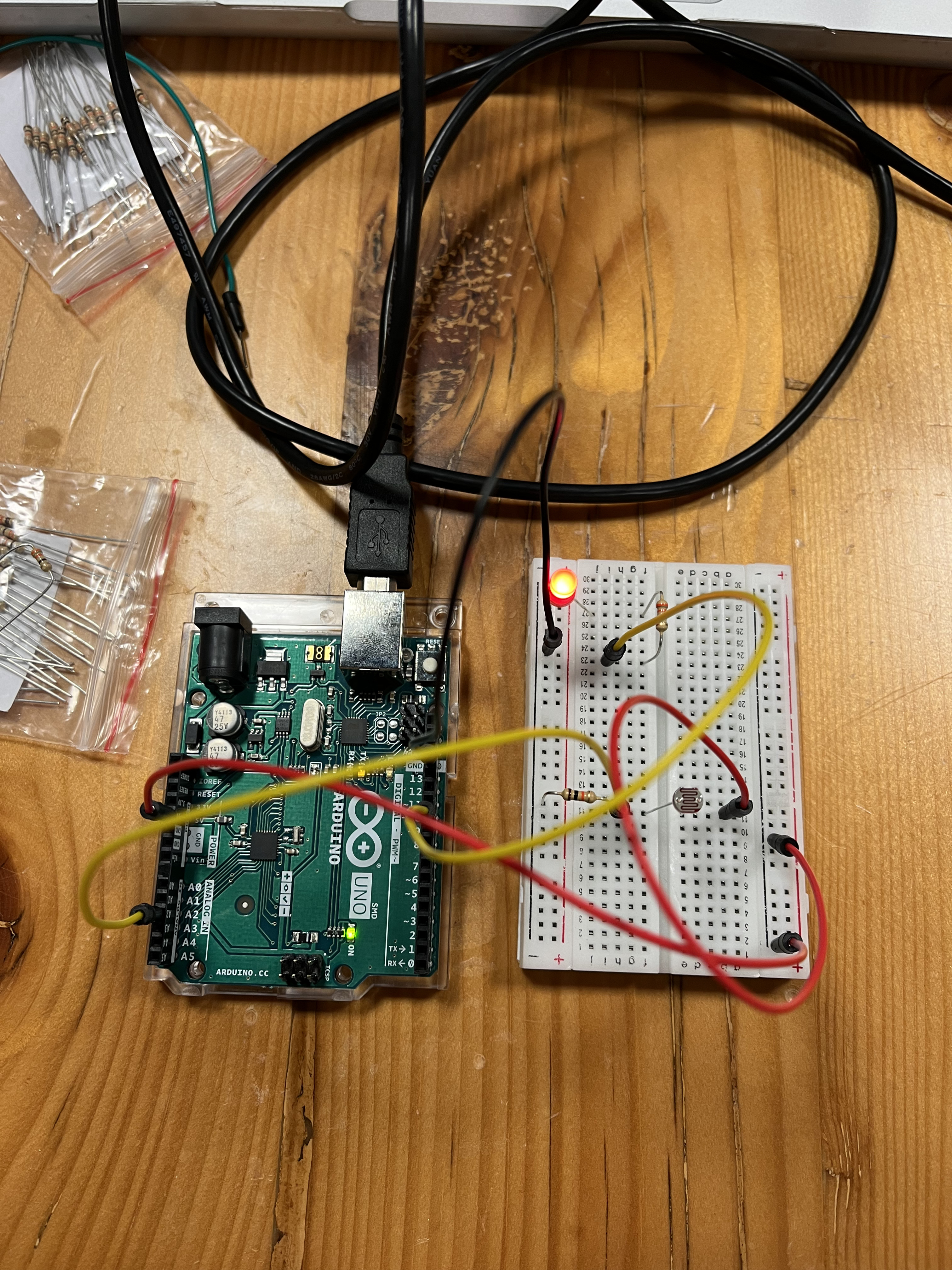
I first began creating the analog sensor, because I was more confident with this one since I almost finished it during last Thursday’s class time. I followed the analog schematic sketch that professor provided in our class lectures, and then I simply attached a red LED light to the circuit to make it be connected to the analog sensor. However, I hit a wall when I tried to control the red LED light’s brightness via analog sensor; although the serial monitor showed that my serial print sensor value was reading correctly, the data was not transfer into my LED light for some reason. Thankfully, I was able to consult Professor Shiloh because I was working in the lab, and he told me that I had connected one of my wires in the wrong place – I had forgotten that only the numbers with squiggly lines are the ones that work for analog circuits, and I had plugged it into 13, which was a non-squiggly number. I also had to fix digitalWrite to analogWrite before I could have the operation run smoothly. Here’s a piece of my code after I had fixed it:
void setup() {
  // analog
  Serial.begin(9600);
  pinMode(10, OUTPUT);
  pinMode(A2, INPUT);
}
void loop() {

  //analog
  int sensorValue = analogRead(A2);
  Serial.println(sensorValue);
  delay(1);
  analogWrite(ledRED, sensorValue);
}
After that was done, this was what I had:
…and here’s a video of it running: IMG_9766 2
Then, I moved onto the digital sensor part, which was a little bit more challenging for me. For this I also referred to professor’s example that he gave during lectures, which was this one: 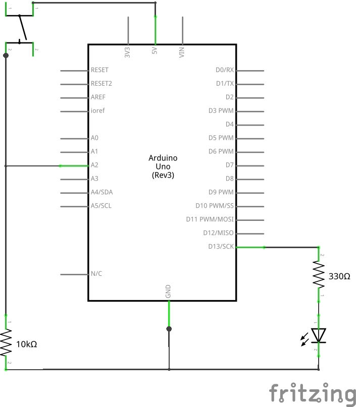
I basically combined this one and the analog circuit I made earlier, and I also wrote out the code for controlling the blue LED light with the button that I added. Here’s the code that I used for it:
int currentButtonState = digitalRead(buttonPin);
  // if the button is currently being prssed down, AND during the last frame is wasn't pressed down
  if (currentButtonState == HIGH && prevButtonState == LOW) {
      // flip the LED state
      if (ledState == HIGH){
        ledState = LOW;
      } else if (ledState == LOW){
        ledState = HIGH;
      }
However, when I tried to run the entire code, I realized that only the red LED light was still flashing, but the blue LED light was not on at all. I tried changing the code, but even when I changed it so that the blue LED light was on the whole time, it stayed constant without responding to the button. I couldn’t figure out the problem, so I even asked one of the lab assistants, and we played around with the circuit wires till we realized that I already had a wire from the analog circuit plugged in at 5v, when I also needed to plug in a wire connected to the button in that space as well. So when I plugged in the wire from digital circuit after pulling out the analog circuit wire, the blue LED light responded to the button correctly!
However, because I had to make space for the digital circuit, this meant the red LED light wasn’t going to work; although I’ve tried to play around with different positions of the wires and on the breadboard, I couldn’t get both to work simultaneously but rather separately on their own.
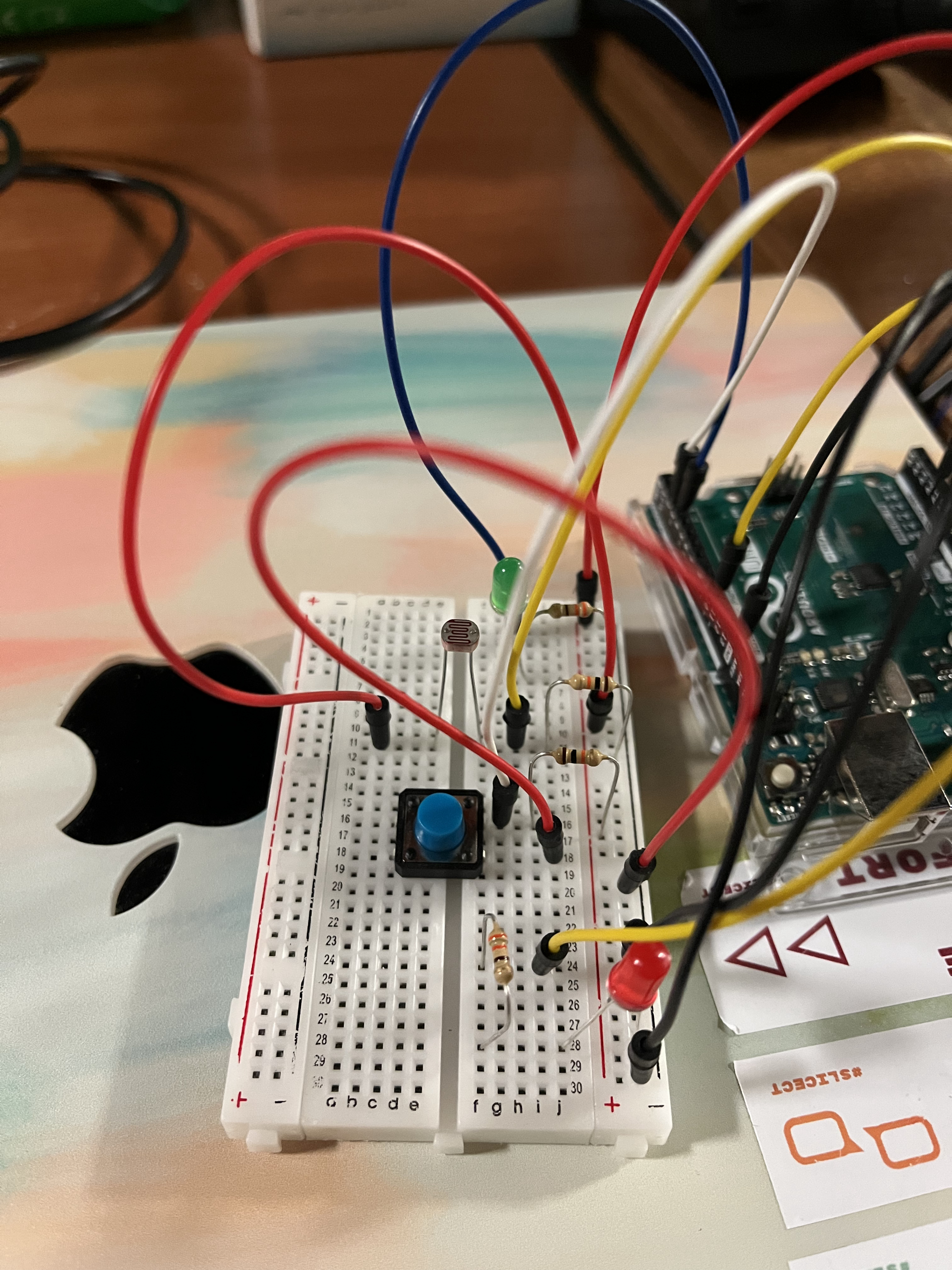
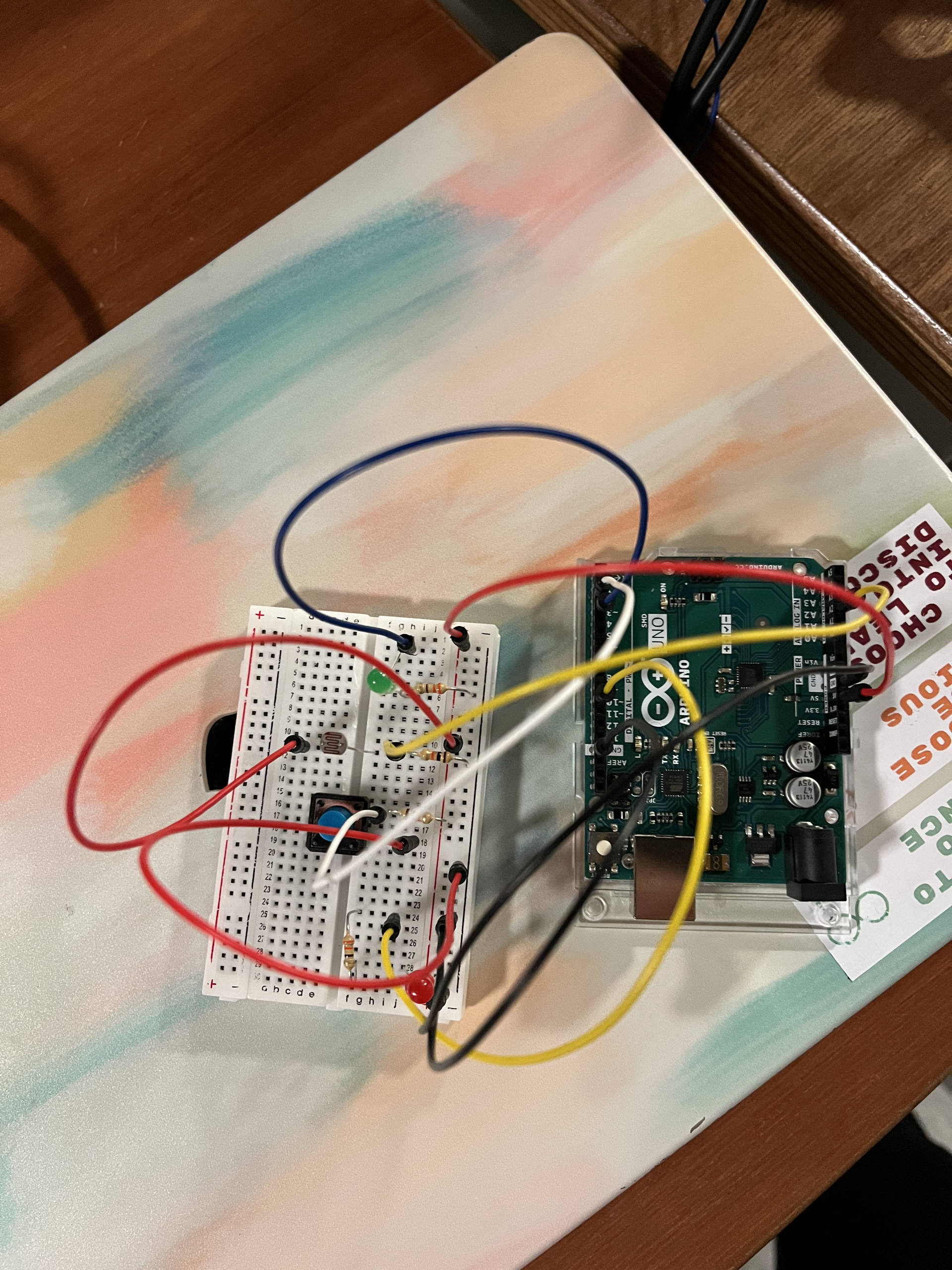
Here’s what I had by this point of the progress: 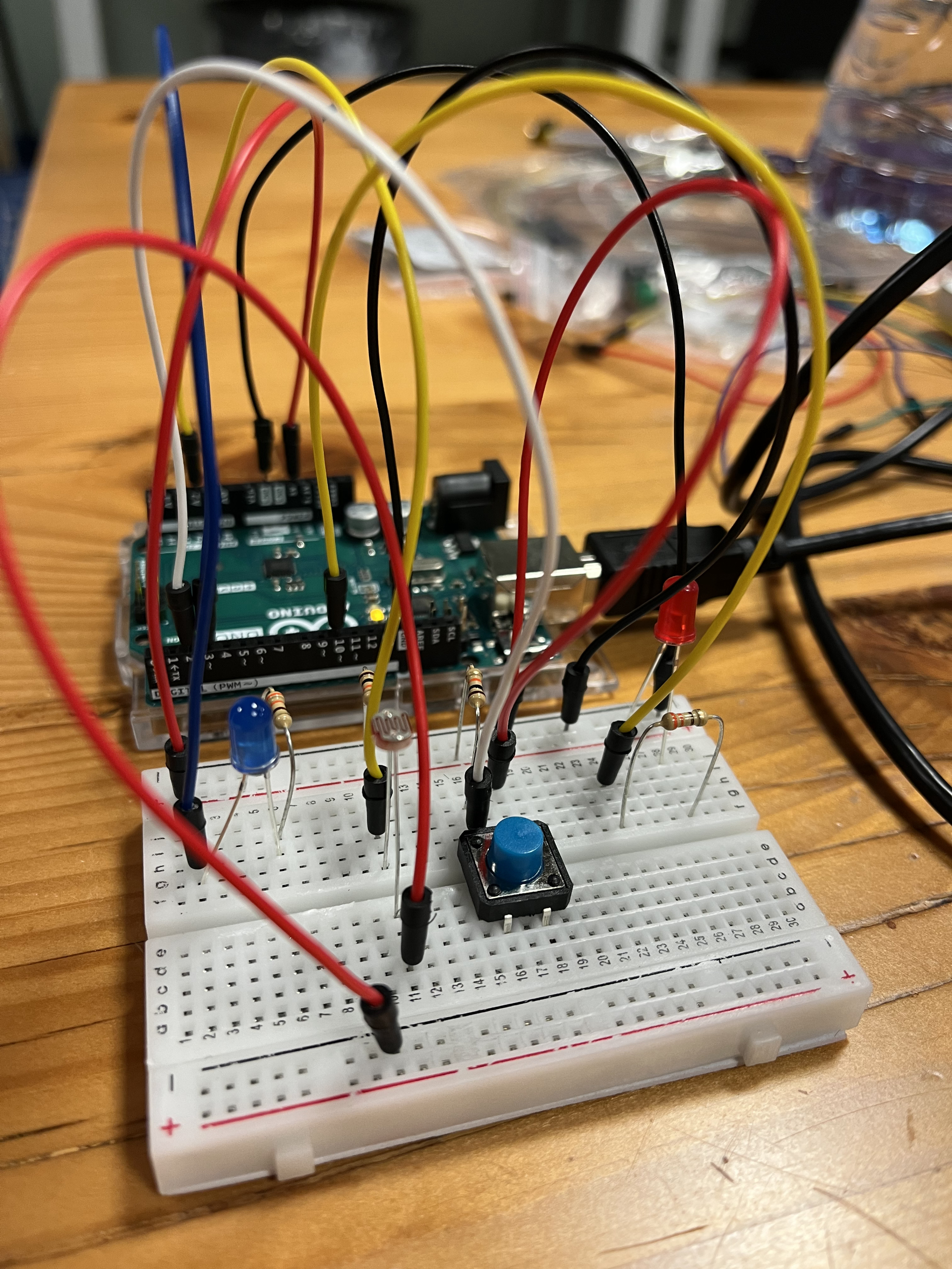
At this point I was on the verge of giving up…but thankfully Professor Shiloh came to my rescue as usual! Turns out I just had one of the red wires’ ends plugged in a wrong hole of the breadboard (pictured below) – when I switched the end over to the other side’s ‘+’ strip and plugged it in there, both lights started operating smoothly! 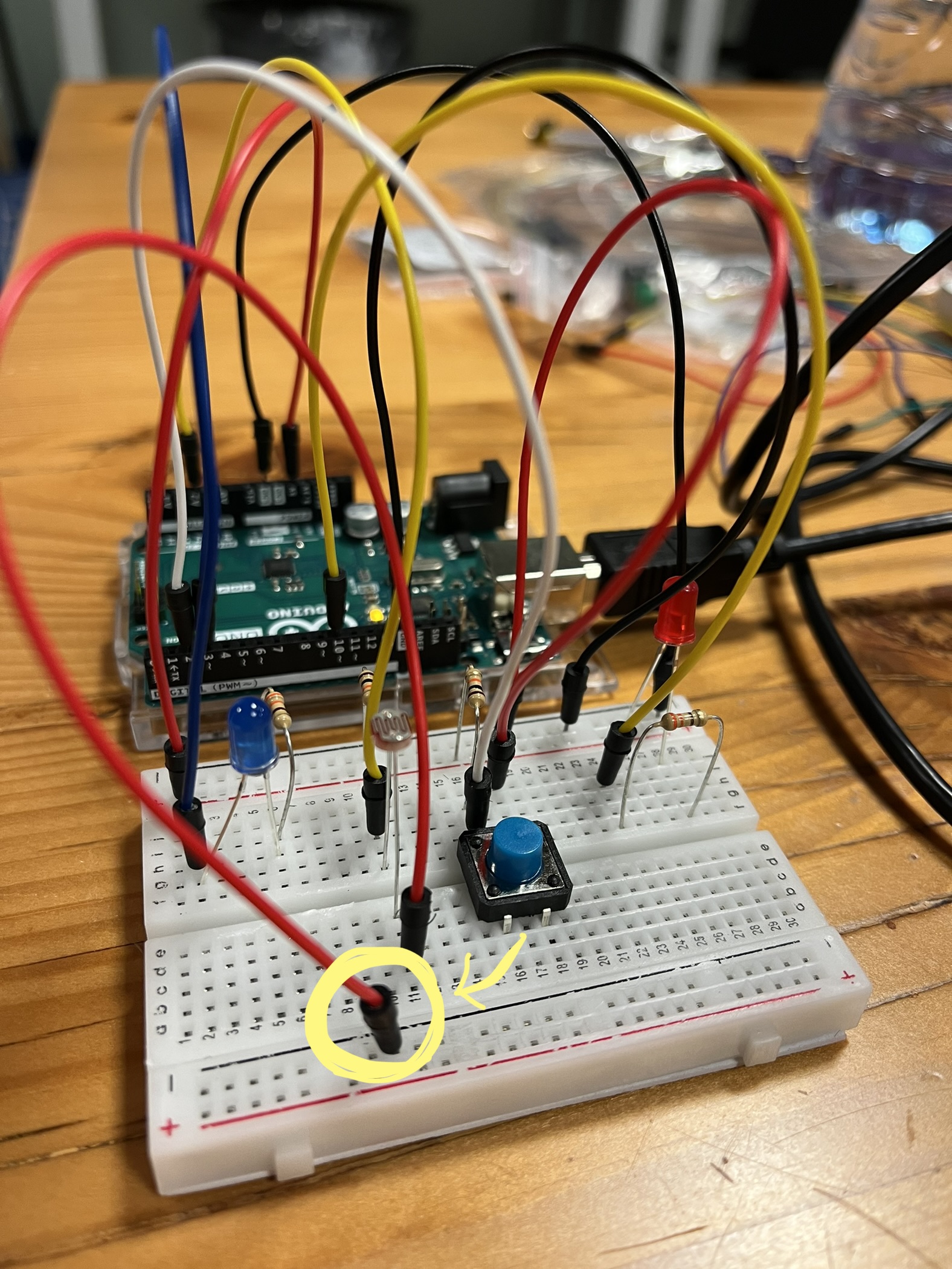
At this point, I had the idea of making my project related to Christmas, so I took care of some of the details such as:
- Picking a song as the background soundtrack that my lights were going to operate to. I ended up choosing ‘Silent Night’ by Michael Buble (the king of Christmas songs, period) because it was nice and slow, which made the switching between the lights easy.
- I had to move locations because the lab lights were too bright, thus making it harder for the LEDs to be depicted on camera. Thankfully, the outside was a perfect location because it was already pretty late at night, making the surroundings dark so that the LEDs could really pop against it.
- I controlled the blue light with a button and the red one with my fingers.
Final Product:
I had to break down the video into smaller clips because the file was too big, but here they are, along with the photos:
Reflection:
Despite the very rough start and almost having an even worse ending, I’m glad I stuck with it till the end and asked for help – it was so satisfying to see how everything clicked and operated at the end! Rewatching the video also cracked me up because my stiff, amateur controlling of the LEDs was a stark contrast with the song’s solemn vibe, haha. Something I’d like to fix next time is making the red LED (the analog one) more easy to control because it was hard for me to turn it off completely with my fingers. But overall, it really put my skills to test and was a fun project to work on!