
Concept
For this assignment, I wanted to replicate the functionality of a volume knob but in the form of a switch. In other words, it would be a non-continuous electrical switch (unlike the volume knob) that serves as a three-way switch. Plus, my initial thought was to implement it in some kind of musical instrument, thus I ended up with a combination of (1) a three-way switch and (2) a guitar multipurpose pedal.
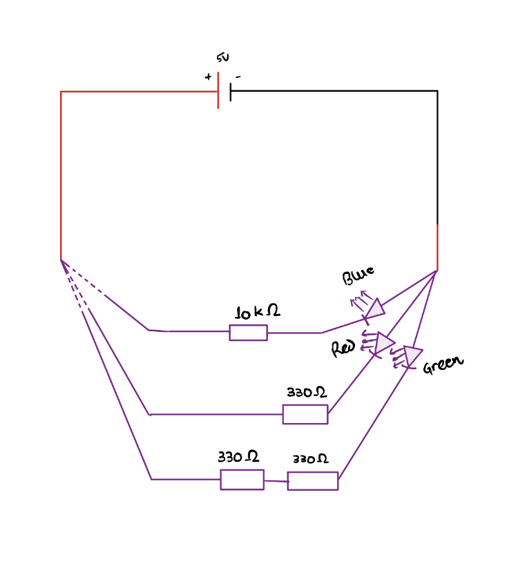
The rudimentary electrical circuit that has been implemented using the breadboard is based on the diagram given above.
Here, we can see that three sets of resistors are connected in parallel to the negative end of the power source. The first branch of the resistor is a single resistor of resistance 10 kΩ (kiloOhm), which is connected to a blue-colored Light Emitting Diode (LED) that enables a single directional flow of current. The second branch consists of a single resistor of resistance of 330 Ω, which is connected to a red-colored LED. Finally, the third branch consists of two resistors (connected in series) of resistance 330 Ω each (total resistance 660 Ω). Each branch is connected to the positive terminal of the power supply, which is facilitated by the use of a switch.
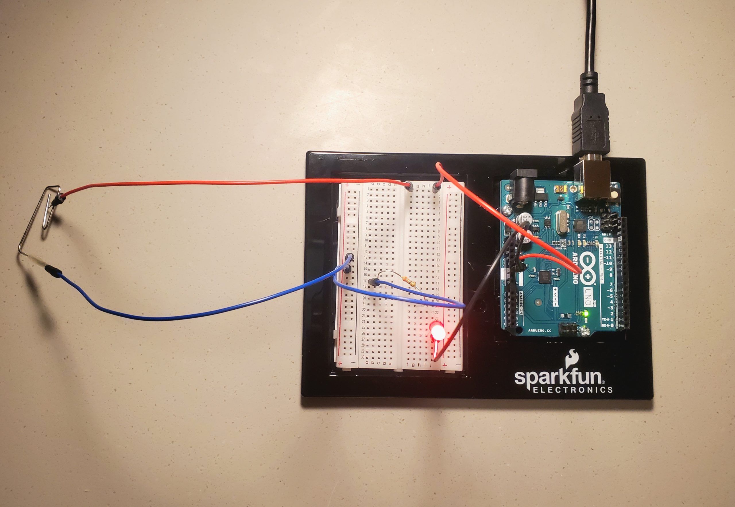
I completed the circuit design in steps. The first step was to complete the 330 Ω branch connected to the red LED. In the circuit, a blue cable has been used to connect the resistor and the switch.
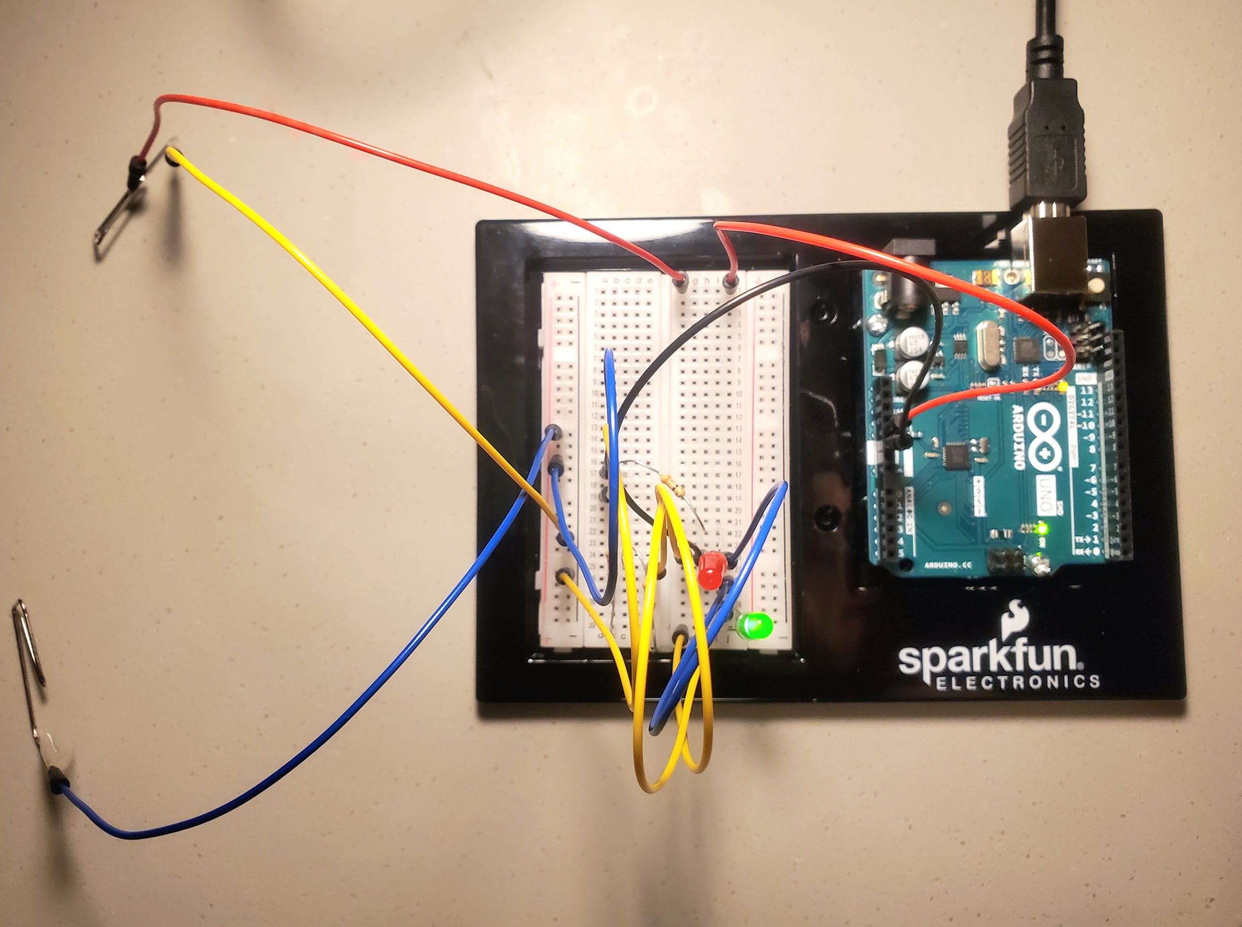
The second step was to complete the 660 Ω branch connected to the blue LED. In the circuit, a yellow cable has been used to connect the resistor and the switch.
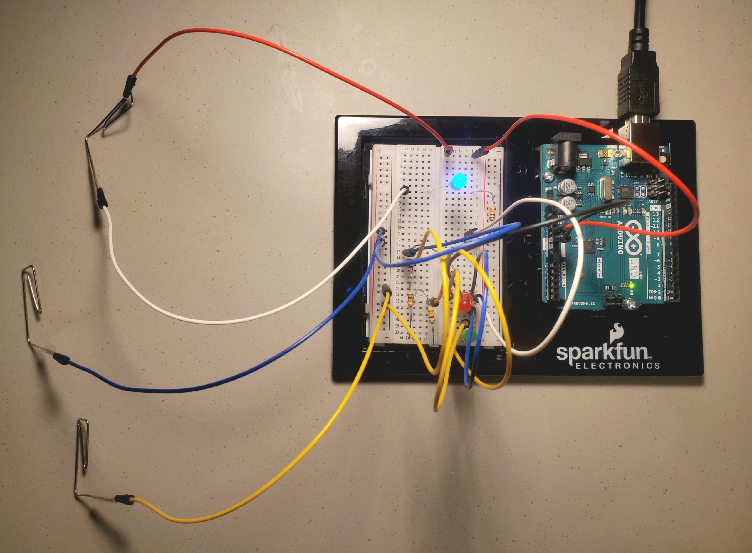
The third step was to complete the 10 kΩ branch connected to the blue LED. In the circuit, a white cable has been used to connect the resistor and the switch.
Now, the design of the switch involves the use of a multi-effect guitar pedal. Since its three pedals (labeled A, B and C) are made of conductive material, I connected the wires using paper pins. The red wire (connected to the positive terminal) can be connected to A, B or C, which in return completes the circuit and as we move the wire to different pedals, different LEDs light up. For instance, connecting the red wire to pedal A (330 Ω) causes the red LED to light up; connecting the red wire to pedal B (10 kΩ) causes the blue LED to light up, and connecting the red wire to pedal C (660 Ω) causes the green LED to light up.
View on YouTube here.
Reflection/ Improvements
The use of a switch with multiple pedals enables a variety of purposes in real-life situations. Since there are resistors of different resistances connected to individual components, suitable pedals can be used to complete a circuit. In order to improve on this project, longer electric cables can be connected to the red wire, which again will be attached to the shoes using double-sided tape. For now, I have attached the (red) cable to one side of the double-sided tape; its second side should be glued to the shoe for optimum use.
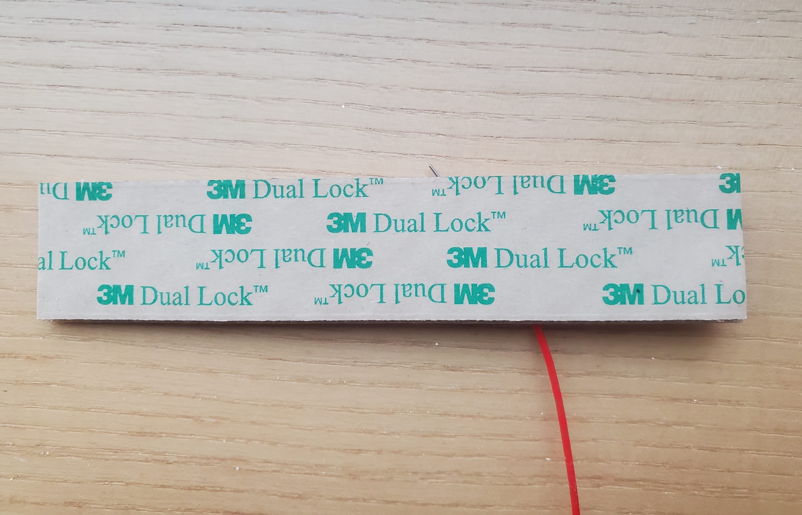
As a result, the indirect involvement of hands can be totally substituted by legs. Then, using legs, the required pedals can be selected and pressed to light a particular LED. Thus, gluing both sides of the double-sided tape (one to cable and the second to shoes) will improve the design. Overall, I am happy with the way this project got shaped to be.