In week 8, we were given task which involved using Arduino and hardware. We had to create a unique & creative type of switch which could be operated without the use of our hands. By using this switch, we could turn the led on and off as required. So, I mainly learnt about building a simple led circuit using both the breadboard and resistor. I have built an aluminium foil-based switch platform separated by a non-conductive foam which is operated by force. So, the switch on happens by applying force on the platform.
IDEA:
I decide to make my own switch using conductive foils on cutted foam boards which was then separated by a non-conductive material. One side of the stranded wires were stuck to the foam board with the aluminium, using a clear tape and the other side of it which was stripped was connected with the jumper wires stripped using an electrical tape. At last, due to force, the terminals would come in contact with each other and circuit would be complete, thus LED would turn on and as the person stands up, the led would turn off.
INSPIRATION:
COVID-19 has become our new normal. Wearing masks, social distancing, constant use of cleaning wipes and sanitizers until our hands dry out is now integrated into our daily routines. This project was inspired by the COVID-19 regulations, specifically the social distancing requirement. In public seating, there is a required empty seat to be set empty between an individual and the person sitting next to them. What is currently being used are stickers and/or tape indicating on which seats it is permitted to sit. This project aims to improve this application. Every time someone sits on an undesignated seat, the LED lights up to tell the person to change their seat. This project’s purpose is to further develop and add technology to accommodate our new normal.
CHALLENGES & PROBLEMS:
The concept I had finalized for completing this task involved was the use of two aluminium foils which had to be wrapped around a carboard sheet and separated by a non-conductive material. Also, I had to find a way to stick the wires to the aluminium foil as soldering would not make them hold on the foil. Thus, since I had not worked on wiring and hardware much before, using the hardware was new for me. Another things I had to be very careful about is not to mix the +ve and -ve supplies as it could lead to the system getting damaged. The jumper wires were not fitting the Arduino board completely which made me put some force which bended some of them. So , now I take on the lesson that it only needs to be in-tact, no need to be fully on. To conclude, the entire process of sticking wire to the aluminium foil took a lot of time as the tape was not sticking to the foil. Thus, this was a very important process as without this, the switch won’t work for me, but eventually it all worked out.
PROCEDURE:
The first target was to blink an LED using Arduino and to do that I have gathered the following hardware:
Arduino board - LED - Resistor of value 330 Ohms -Jumper wires - USB Cable
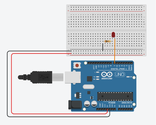
The circuit diagram which we referred was as following:
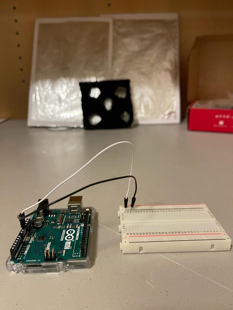
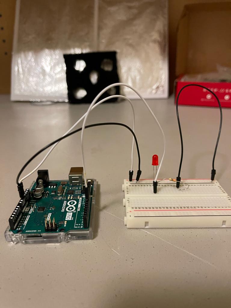
So, I used the hardware to power the + and – rails of the breadboard so that the entire circuit can use + and – from these rails if and when required in future connections. In the following image, the white wire goes into the +ve rail and the black wire goes into the -ve rail.
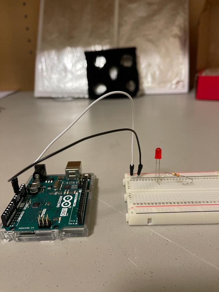
Next, we used a led, identified its Anode and Cathode (cathode has the shorter leg), and connected a resistor with it as shown. Resistor is used to limit the current through the led. We chose a value of 330 ohms as we read that led requires 20 – 25 mA of current for proper operation so resistor value of 100 ohms to 330 ohms work well.
Then I connected the other end of resistor to the ground to give it a -ve or GND signal
In this step, I connected the digital pin 7 from Arduino to Anode of led using a yellow jumper wire as shown.
Afterwards, I wrote a simple program to blink the led connected to digital 7 and uploaded it to our Arduino board by using the following settings on Arduino software. I selected usbmodem 143141 (Arduino Uno)
// C++ code
//
void setup()
{
  pinMode(7, OUTPUT);
}

void loop()
{
  digitalWrite(7, HIGH);
  delay(1000); // Wait for 1000 millisecond(s)
  digitalWrite(7, LOW);
  delay(1000); // Wait for 1000 millisecond(s)
}
Once the code was uploaded, we could see the led blinking on and off with a gap of 1000 ms
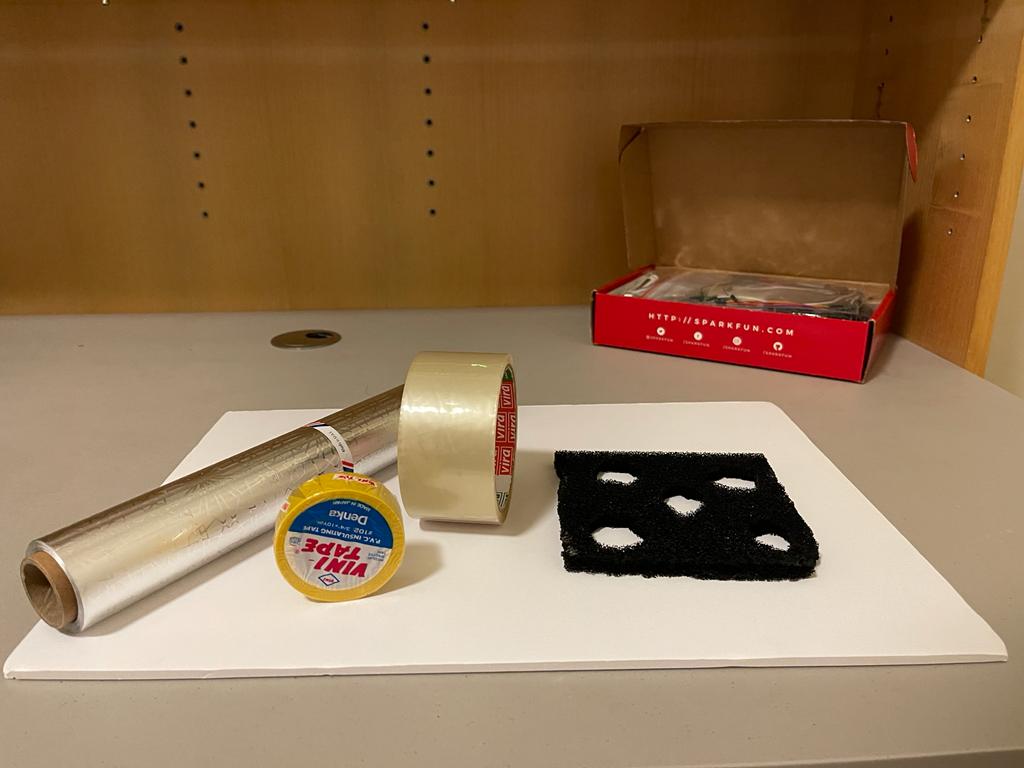
Once my LED circuit was complete, I started gathering material for making my own switching platform.
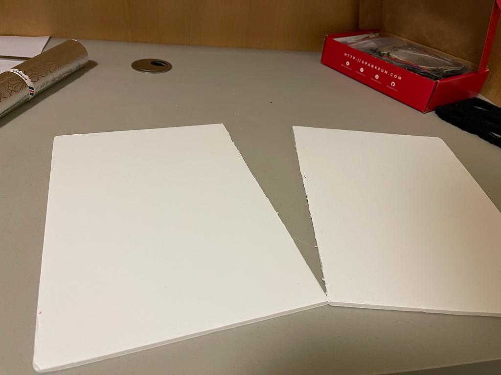
Next, I have cut the carboard in two different parts and these would serve as two different terminals of the switch.
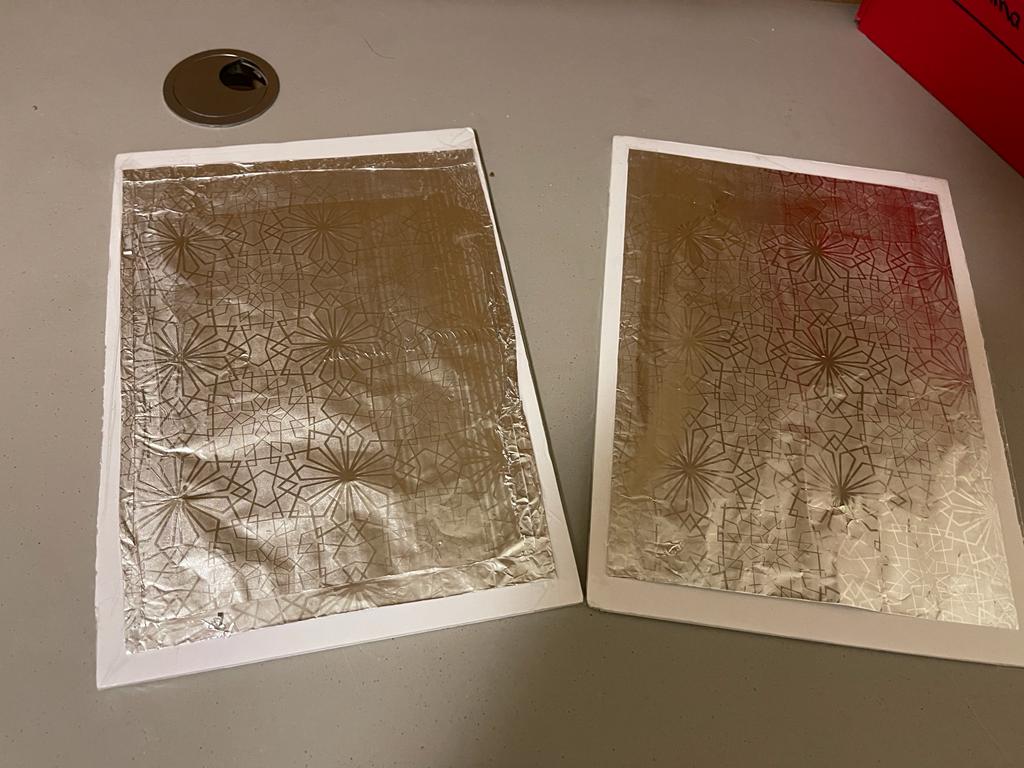
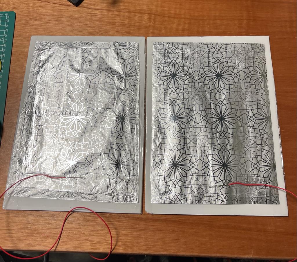
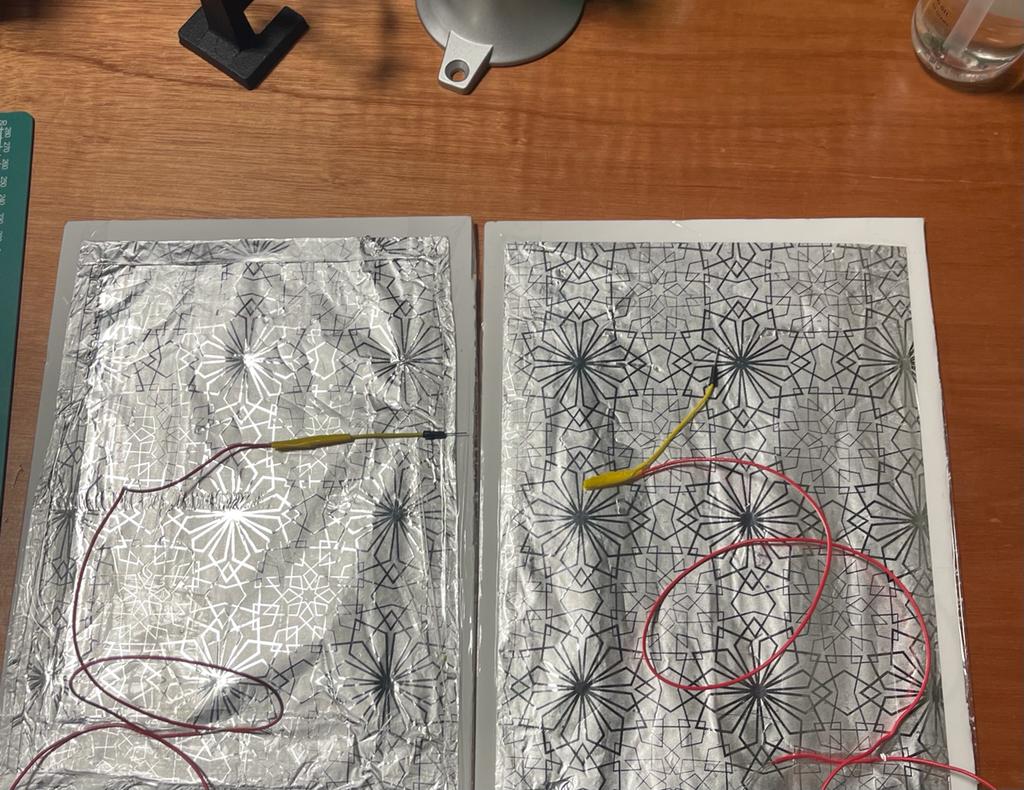
Then I used foil and put it on the foam cardboard using clear tapes as shown.
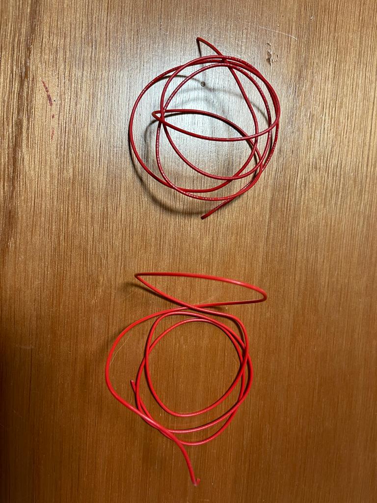
Now, I needed multi-strand wires to be connected to the foil. So, I used a single wire and cut it into two parts using a cutter, one for each foil board.
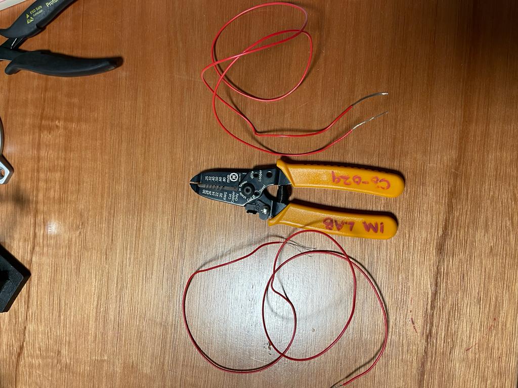
Using a wire stripper, both the ends of the two pieces of wires were stripped like shown
Afterwards, I used electrical tape to stick one end of each wire to the foil in such a way the wire strands were in contact with the conductive surface of the foil.
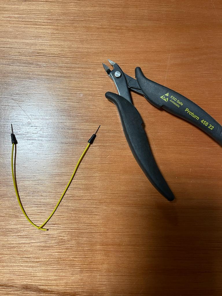
Later, I used a male-to-male jumper wire and cut it from middle using a wire cutter.
The other end of the wires taped to the foil was taped to male end of jumper wire as shown below.
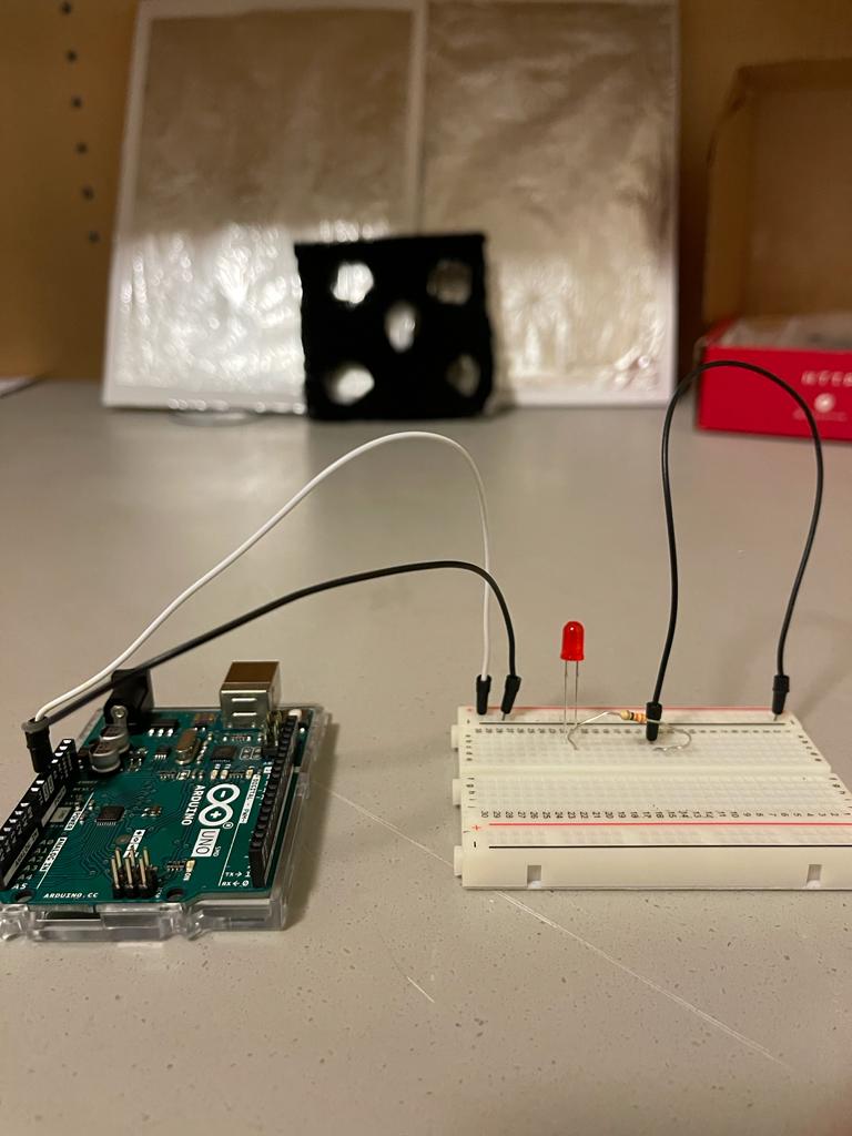
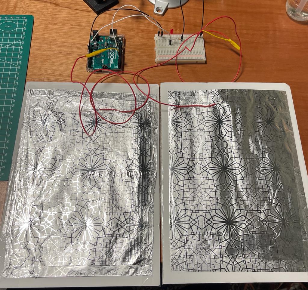
Now, I am ready to test my switch with my led circuit. I connected one foil arrangement to ground and the other was connected to a digital IO of Arduino as per my code.
The, I used the following code in my Arduino circuit and tested the foil switch which I made.
// C++ code

int led = 7;
int sensor = 6;

void setup()
{
  pinMode(led, OUTPUT);
  pinMode(sensor,INPUT_PULLUP);
}

void loop()
{
  if(digitalRead(sensor)==LOW)
  {
    digitalWrite(led, HIGH);
  }
  else
  {
    digitalWrite(led, LOW);
  }
}
So, I observed that the LED switched on once the two foils were made in contact with each other and switched off once the foils were separated which is how a switch works.
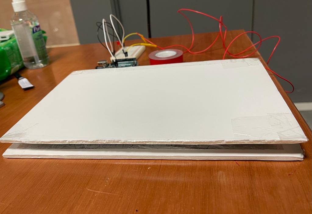
At the last step, I used the black non-conductive foam as a separator between the two foil boards and put everything together like a sandwich in which the non-conductive material ensured the foil would turn on only if someone puts force on the two boards. In this case the two foils would come in contact and the LED would turn on. The final arrangement looked like this.
FINAL WORK:
CONCLUSION:
There were a lot of ups and downs in this assignment, but I pulled it off at the end and had a great time exploring with the construction of my mini project. Furthermore, I will hopefully be taking this experience to achieve much more complicated tasks in the future.
HOPE YOU ENJOYED , HERE IS THE FULL CODE with the comments 🙂
// Shamma's Sit at your own risk Program
//C++ coding in Ardiuno

// Setting Global Variables
int led=7;
int sensor =6;


// This code runs only once
void setup()
{
  // only declaring input and ouput
  pinMode(led, OUTPUT); //  define the LED connected on pin 7 as an output

  // I did not use the input because it wont work properyly with what I builded
  // So,  input_pullup was used because it requires no external components and can be turned on & off in software during program execution
  //Another thing is that is it used to read switches properly and prevent missed readings
  pinMode(sensor,INPUT_PULLUP);// the proximity sensor acts as an input devide which will take an anction , in our case presnece of an obstacle
}


// This runs forever as long as system is turned on
void loop()
{
  if(digitalRead(sensor)==LOW)// reading if an obstacle (someone infront of sensor) is present
  {
    digitalWrite(led, HIGH);// turning on LED by giving the anode of LED +5 volt signal

  }
  else
  {
    digitalWrite(led, LOW);// if no one is present, turn off LED by giving low signal
  }
}