For probably the first time since we started the semester, I was able to do a weekly assignment just as I planned it initially. As soon as we were assigned to include some analog sensor in our circuit and a digital one, I thought of the photocell (because it’s just so cool) and some application of it where the environment is dark and then is bright. I thought of having three bulbs, red, yellow, and green and as you get closer with your finger it changes from red to yellow to green. Then I thought of drawing a rabbit and a turtle and having bulbs as their eyes; if you get too close then the rabbit’s eyes brighten up, but if you are too far (bright environment) the turtle’s eyes brighten up. But after a long time brainstorming, I decided to go with the most intuitive idea relating to darkness and light: day and night in real life.
Artistic (not so much) steps:
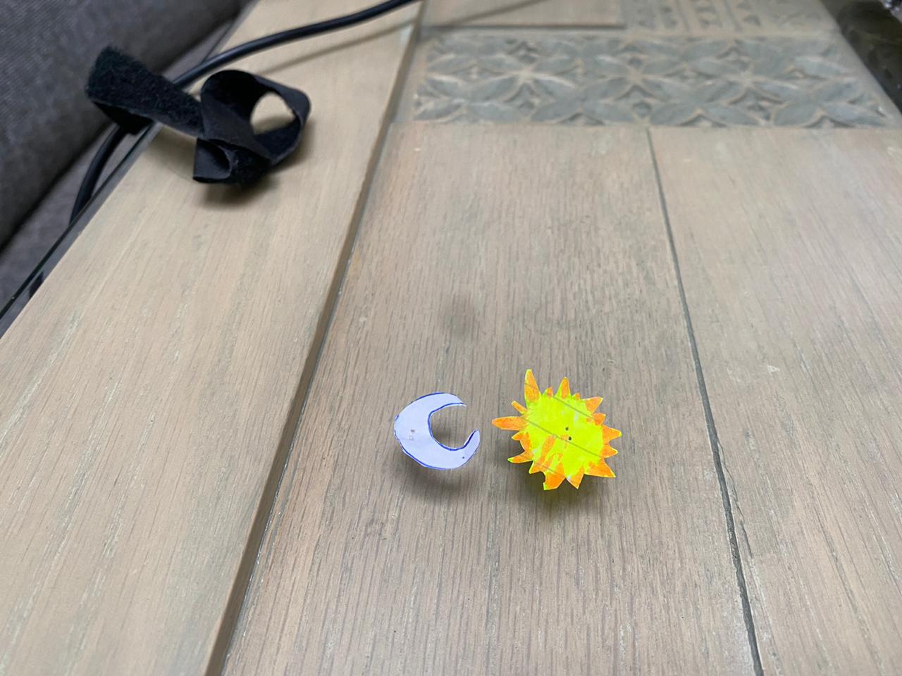
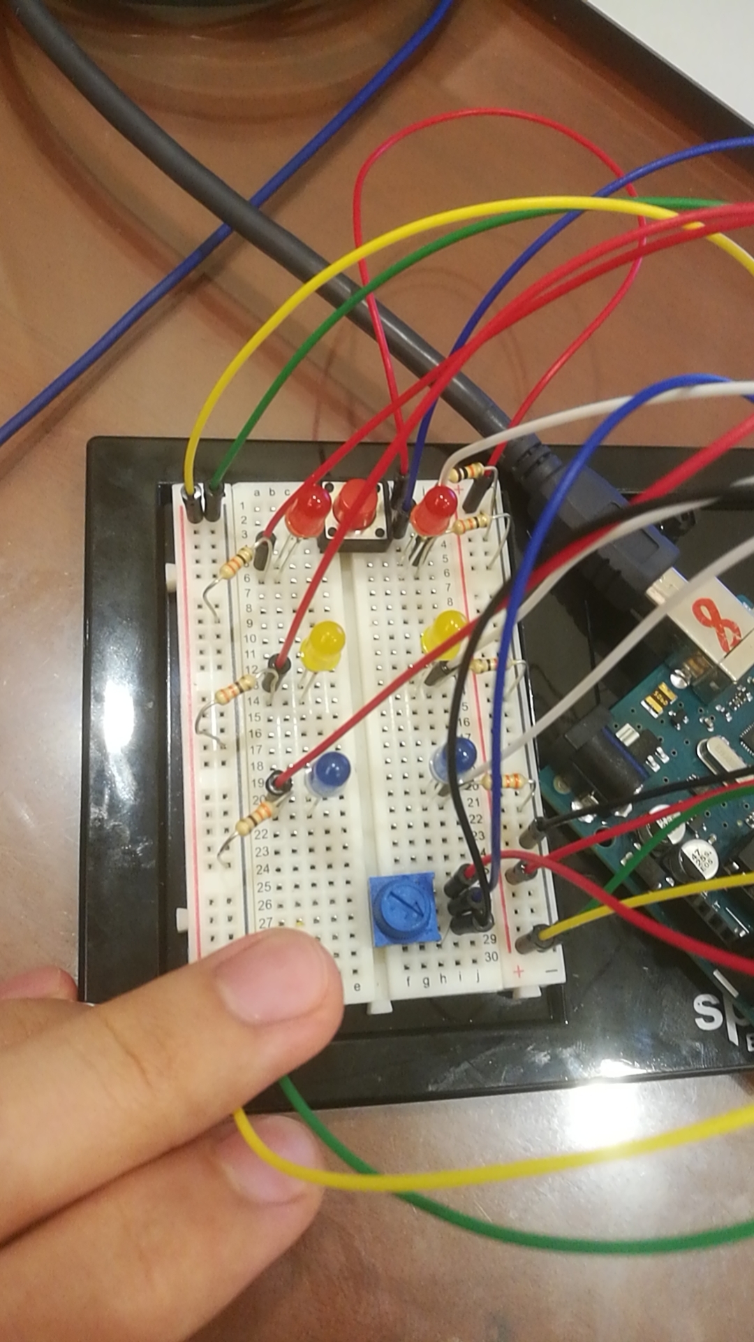
As visible, I draw small icons of the sun and the moon in order to represent day and night, where the yellow bulb would sit in the middle of the sun, and the white bulb will sit in the middle of the white crescent.
Process:
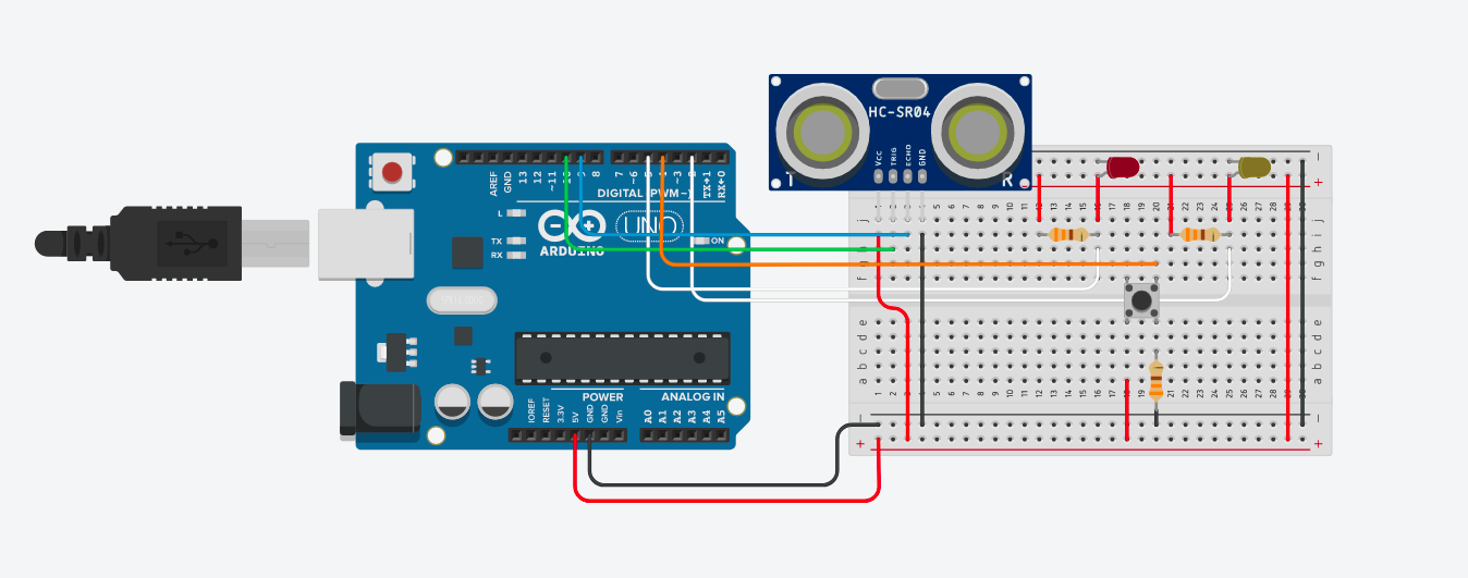
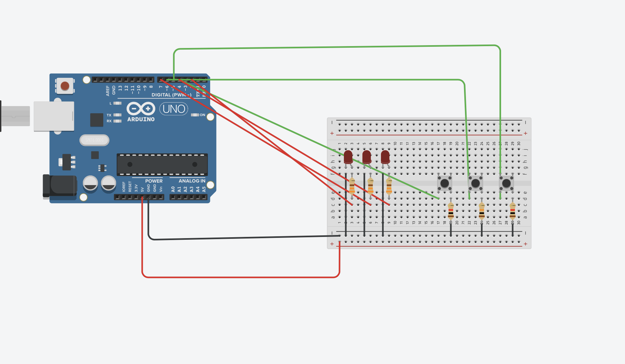
Learning from last assignment, I extrapolated the power and the ground to the rest of the board using two jumper wires, in order to give myself extra space to work with.
I put a button the middle as some kind of digital switch for the whole simulation, if you click once, it’s on and stays on until you click once again.
I put both bulbs in pins with the “~” sign next to them so that their pulse can be changed using the photocell readings.
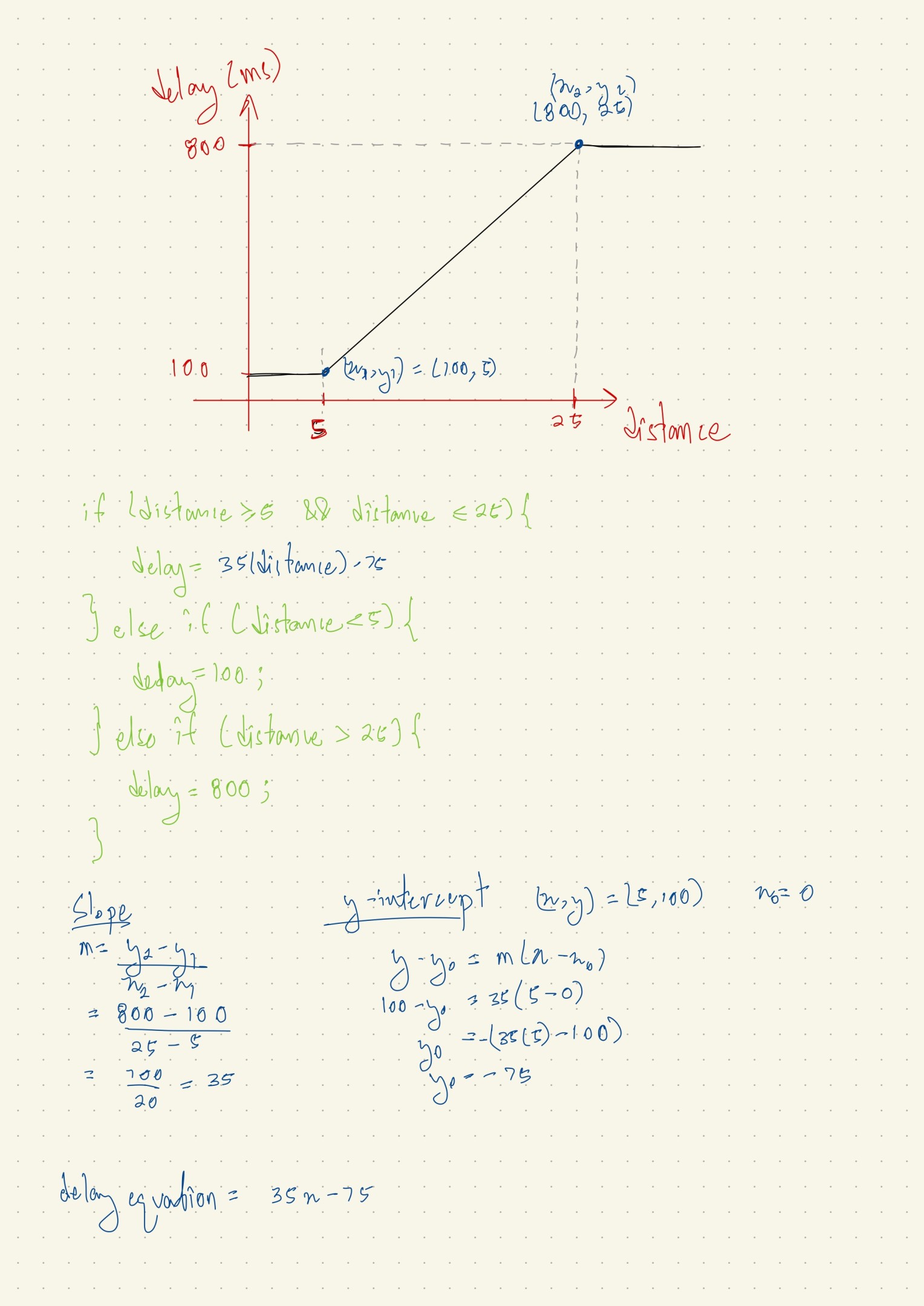
I decided to make the simulation so that the yellow bulb is very bright (bright sun at the beginning of the day), and as you get your finger closer (as time passes throughout the day and light lessens) the brightness decreases until at one point it stops completely (the evening), and as you continue to get closer, the white bulb of the moon becomes brighter and bright (through the night), until it’s maximized when you physically touch the photocell and block almost all light (midnight), then as you move your finger back upwards the opposite happens (after midnight until dusk). The key is that I map the first values until half of the maximum reading of photocell into inverted values for the bulb so I would get that effect of a spectrum.
Struggles:
The only problem I faced was with the if conditions and digital/analog writing bearing in mind that I always do analogRead(); if I only had analogwrite() then the bulb would keep being bright, and of it’s only digitalWrite() then the bulb doesn’t turn on at all. I’m sure I had some errors in there which I was not able to deal with. So I decided to have two scenarios, if the simulation is on, read photocell and analogWrite() based on that, and if simulation is off then digitalWrite() the bulbs to be off.
Also, when I forgot to make “prevButtonState = buttonState” at the very end and rather had it inside the if statement, everything would work incorrectly, so that was another thing I learned.
The last issue was just that I had a non-working jumper wire, and a bulb that was probably not 100% functional, which caused some confusion for me at first but soon I realized the issue and resolved it.
Final Project Angle 1:
Final Project Angle 2:
The code for the assignment:
int button = 2;                 //button pin

int ledWhite = 3;               //white bulb pin
int ledState1;
int ledYellow = 5;              //yellow bulb pin
int ledState2
bool prevButtonState = LOW;     //initializing button to be unpressed

int knob = A0;                  //pin of photocell

void setup() {

  pinMode(button, INPUT);         //button initialized as input
  pinMode(ledWhite, OUTPUT);      //bulbs initialized as outputs
  pinMode(ledYellow, OUTPUT);

  Serial.begin(9600);
}

void loop() {
  int buttonState = digitalRead(button);              //storing reading from button
  Serial.println(buttonState);

  if (buttonState == HIGH && prevButtonState == LOW) {      //if button is clicked change the led states to their opposites
    ledState1 = !ledState1;
    ledState2 = !ledState2;
    }

  if (ledState1 == HIGH && ledState2 == HIGH) {           //if the bulbs were previously off then were turned on by button
      int knobValue = analogRead(knob);                   //store reading from photocell
      int mappedValue1 = constrain( map(knobValue, 596, 850, 0, 255), 0, 255);        //map the values from half the max until the max of the photocell readings into 0 -> 255 so that as they increase teh brightness increases, and constrain that within 0 to 255
      int mappedValue2 = constrain( map(knobValue, 340, 595, 255, 0), 0, 255);        //map the first values until half the max of photocell readings into 255 -> 0 so that as they increase the brightness decreases, and constrain that within 0 to 255


      Serial.println(knobValue);

    analogWrite(ledYellow, mappedValue1);             //change output of sun bulb accordingly
    analogWrite(ledWhite, mappedValue2);              //change output of moon bulb accordingly
    }

  else {
    digitalWrite(ledWhite, ledState2);              //make bulbs's state = LOW, hence turned off
    digitalWrite(ledYellow, ledState1);             //make bulb's state = LOW, hence turned off
    }

  prevButtonState = buttonState;                    //update prevButtonState in each loop
}
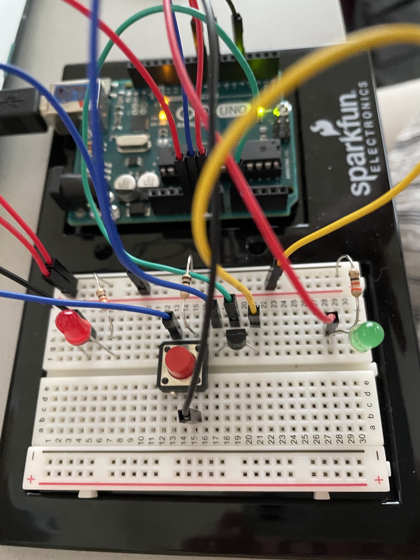
 Final Setup