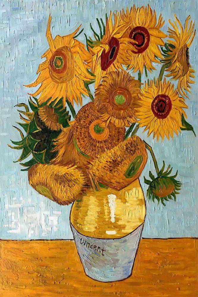
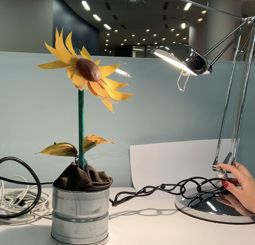
My inspiration for this project was a painting by my favorite artist Van Gogh (the Sunflowers) and I also wanted to create something that I would want to keep in my personal space. Therefore, my midterm project was a mimic of a ‘sunflower’ – a flower that would follow the direction of light.
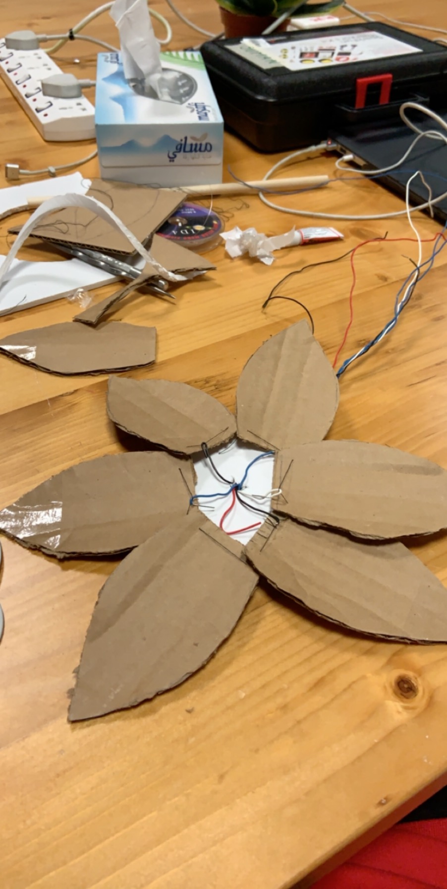
I initially also wanted to make a flower that would open and close (as recommended by Aaron but despite trying to different methods – I felt as if I would be limited by time if I continued. So instead, I created my final one using two photoresistors and a servo.
For my code, since I used only one pin for both my photoresistors, the code was not too complicated. I used the sensor value (servoValue) to produce the values for which the servo should turn (servoTurn) and initially let this begin at a 90 degree angle. I also added a delay at the end so that allows the servo to reach the position indicated before the sensor senses anymore changes.
#include <Servo.h>

int sensorPin = A0;
int servoPin  = 9;

int sensorValue = 0;
int servoTurn = 90;
int tolerance = 20;

Servo myservo;

void setup() {
  Serial.begin(9600);
  pinMode(sensorPin, INPUT);
  myservo.attach(servoPin);
  myservo.write(servoTurn);
  // sets the degrees to which the servo is to be positioned
}

void loop() {

  sensorValue = analogRead(sensorPin);
  Serial.println(sensorValue);
  // print the sensor values

  if (sensorValue < (340-tolerance) )
    // perform the first check if the value read from before is less than the difference between 340
  {
    if (servoTurn < 180) servoTurn++;
    // ++ increments x by one and returns the old value of x
    // perform a further check that the servo is not > 180
  }

  if (sensorValue > (340+tolerance) )
    // value read by the sensor is compared with the sum of 340 + tolerance
  {
    if (servoTurn > 0) servoTurn--;
   // check that the angle the servo is located is not less than 0
  }


  myservo.write(servoTurn);

  delay(50);
  // allows the servo to reach the position indicated before sensor sensing changes
}
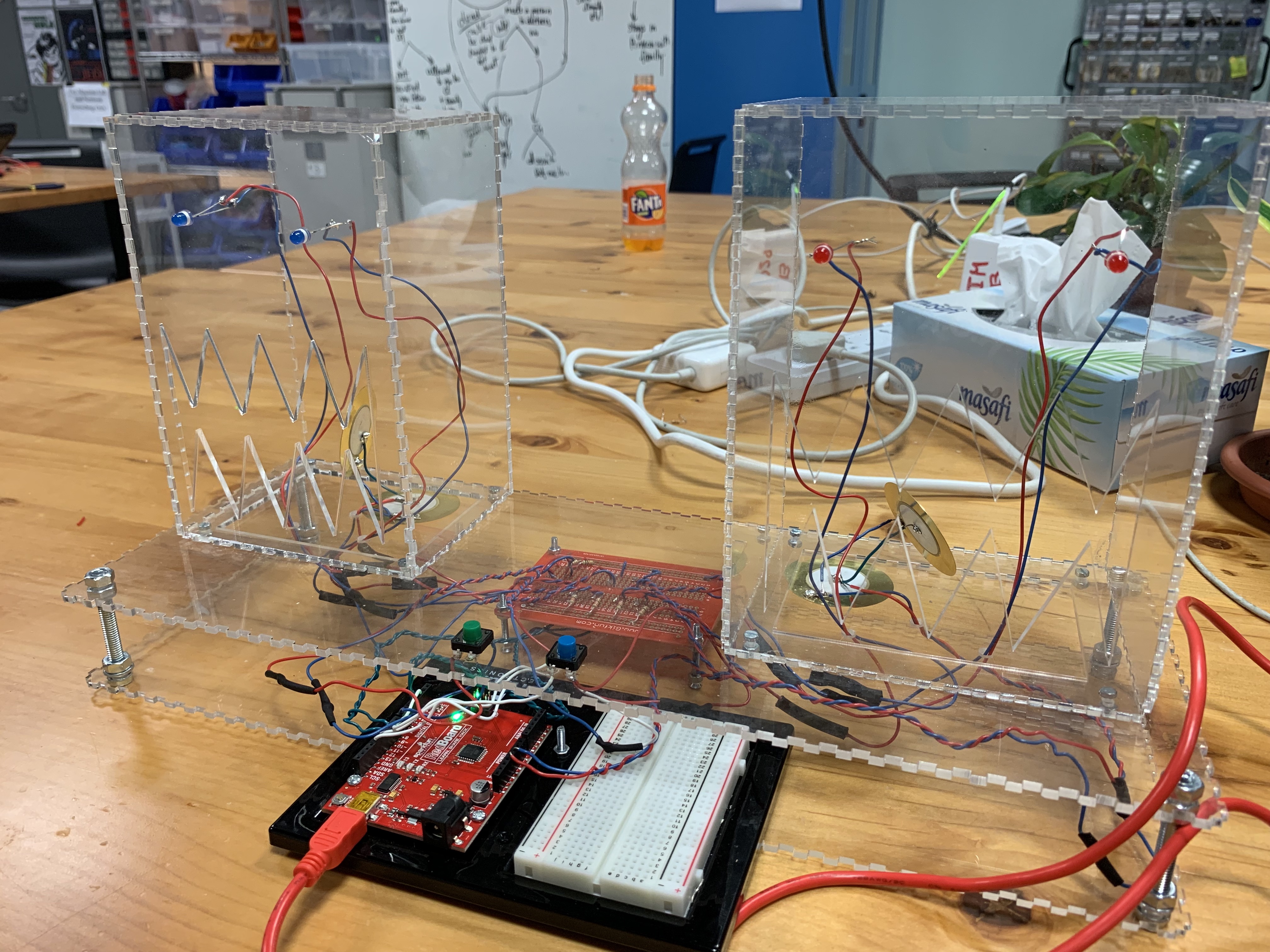
My main interest for this project was the transferring the feedback of one medium to another medium, especially dealing with pattern of sound created using the piezo disc. And, for the midterm project, I have created two monsters: the RED and the BLUE indicated by the color of their eyes, where the blue monster follows the pattern played by the red monster. On the interface, there are two buttons: the green and the blue. When the green button is pressed, the red monster’s LED lights up, the buzzer inside it activates. The duration of the rest period in between the press and the duration of the buzzer activated will be saved, and when the blue button is pressed, the blue monster will follow the pattern that the red monster has played in a continuous loop.
For the structure of the data for this project, I have used the STL library which encompasses vector. Since, an array has to be predetermined with its size, I could not implement the array as my duration container when the length of the pattern is indeterminable. Whereas, using a vector, I can just push_back the new duration at the end – which served as a perfect container for this project.
Initially, I had multiple issue with the difference in the speed of the patter played for either monsters. At first, the saved duration values of the Red Monster were incrementing too fast, which I fixed using the modulus of it by 2500 to slow down the increments. Then, when the Blue Monster was playing the saved pattern, the intended speed of the pattern and the actual speed was different. So, I had to include careful selection of delay values to match them.
An interesting note about the project was that the enclosure was done with a transparent acrylic with the base being open on the sides. According to Critical Interface Toolbox by Joana Moll and Andrea Noni, one of the highlights of the definition of interface was “Users are entitled to know what the interface hides. Access to knowledge is a fundamental right“. Plus, after reading through different examples of the enclosure boxes, I was intrigued by the design of open-sides boxes, especially the “Moshi Moshi” created by Aaron. Therefore, I came to a conclusion to make the container of the project transparent for the audience to see what is happening underneath the system.
[Quick Play-through of the Project]
[Source Code for the Project]
#include <ArduinoSTL.h>

// ===== Declaring Variable Pin ===== //
const int triggerPin = 2;
const int buttonPin = 7;

const int buzzerOnePin = 12;
const int buzzerTwoPin = 13;

const int ledPinOne = 3;
const int ledPinTwo = 4;

const int ledPinThree = 10;
const int ledPinFour = 11;

// ===== Declaring Initial State ===== //
int prevPadState = 0;
int currentPadState = 0;

int currentTriggerState;
int prevTriggerState;

int savedRestDuration = 0;
int savedPlayedDuration = 0;

// Time Duration to slow down the accumulation of saved duration for the later loop
long timeDuration = 0;

// Conditions to check which loop to proceed:
// 1. TRUE :: BLUE MONSTER playing the saved duration of the vector
// 2. FALSE :: RED MONSTER playing and recording the pattern played into the vector
bool playLoopState = false;

unsigned long prevTime = 0;
unsigned long currentTime = 0;

// Interval Index is set as 1 so that when the trigger button is pressed,
// the savedNotes vector is played in the beginning disregarding the first rest period.
int intervalIndex = 1;

int resetIndex = 0;

// The container vector of durations for rest and playing of the note;
// ============================
// The even number index - REST;
// The odd number index - PLAY;
// ============================

std::vector<int> savedNotes;

void setup() {
  //Serial Port begin
  Serial.begin (9600);

  // RED MONSTER Buzzer
  pinMode(buzzerOnePin, OUTPUT);

  // BLUE MONSTER Buzzer
  pinMode(buzzerTwoPin, OUTPUT);

  // button - RED MONSTER
  // trigger - triggers the BLUE MONSTER to mimic the pattern of the RED MONSTER
  pinMode(buttonPin, INPUT);
  pinMode(triggerPin, INPUT);

  // RED MONSTER LEDs
  pinMode(ledPinOne, OUTPUT);
  pinMode(ledPinTwo, OUTPUT);

  // BLUE MONSTER LEDs
  pinMode(ledPinThree, OUTPUT);
  pinMode(ledPinFour, OUTPUT);
}

void loop() {

  currentTriggerState = digitalRead(triggerPin);
  currentPadState = digitalRead(buttonPin);

// ========================================================= //

  if (!playLoopState) {
    if ((timeDuration%2500) == 0) {
      if (currentPadState == 1 && prevPadState == 1) {
        /*
         *  Button is being pressed = the buzzer is playing
         */
        Serial.print("Keep Playing!: ");
        tone(buzzerOnePin, 100);
        savedPlayedDuration++;
        Serial.println(savedPlayedDuration);
      }

      if (currentPadState == 0 && prevPadState == 0) {
        /*
         *  Button is not being pressed = the buzzer is resting
         */
        Serial.print("Keep Resting!: ");
        noTone(buzzerOnePin);
        savedRestDuration++;
        Serial.println(savedRestDuration);
      }

      if (currentPadState == 1 && prevPadState == 0) {
        /*
         *  The first loop when the button is pressed. This means that prior to the button press,
         *  the buzzer was resting. So I saved the accumulated duration of rest at this point.
         */
        tone(buzzerOnePin, 100);
        prevPadState = currentPadState;

        // Start of playing duration;
        savedPlayedDuration++;

        digitalWrite(ledPinOne, HIGH);
        digitalWrite(ledPinTwo, HIGH);

        Serial.print("SAVED REST NOTE :");
        Serial.println(savedRestDuration);

        // Push the rest duration into the vector & reset the duration;
        savedNotes.push_back(savedRestDuration);
        savedRestDuration = 0;

      } else if (currentPadState == 0 && prevPadState == 1) {
         /*
         *  The first loop when the button is released. This means that prior to the button press,
         *  the buzzer was playing. So I saved the accumulated duration of playing at this point.
         */
        noTone(buzzerOnePin);
        prevPadState = currentPadState;

        // Start of rest duration;
        savedRestDuration++;

        digitalWrite(ledPinOne, LOW);
        digitalWrite(ledPinTwo, LOW);

        Serial.print("SAVED PLAY NOTE :");
        Serial.println(savedPlayedDuration);

        // Push the played duration into the vector & reset the duration;
        savedNotes.push_back(savedPlayedDuration);
        savedPlayedDuration = 0;
      }
    }

// ========================================================= //

  } else {
    if (intervalIndex < savedNotes.size()) {
    /* ==========================================================
     * When the blue-button is pressed, the loop iterates through
     * the savedNotes vector from the designated interval index
     * to the size of the vector.
     * ========================================================== */
      Serial.println(savedNotes[intervalIndex]);

      if ((currentTime) - (prevTime) <= savedNotes[intervalIndex]) {
        if ((intervalIndex % 2) == 0) {
          /* =========================================================
           * When the index of the vector saveNotes is an EVEN number,
           * the value of the vector at that index is the duration of
           * how long the "rest" period was. The loop is repeated until
           * currentTime - prevTime is equal to or larger than the
           * duration value of the saved rest.
           * ========================================================= */
          Serial.println("REST");
          noTone(buzzerTwoPin);
          digitalWrite(ledPinThree, LOW);
          digitalWrite(ledPinFour, LOW);
          delay(125);
        } else if ((intervalIndex % 2) == 1) {
          /* ========================================================
           * When the index of the vector saveNotes is an ODD number,
           * the value of the vector at that index is the duration of
           * how long the "played" period was. The loop is repeated
           * until currentTime - prevTime is equal to or larger than
           * the duration value of the saved rest.
           * ======================================================== */
          Serial.println("PLAYED");
          tone(buzzerTwoPin, 500);
          digitalWrite(ledPinThree, HIGH);
          digitalWrite(ledPinFour, HIGH);
          delay(125);
        }
      } else {
        /* ==========================================================
           * When the saved duration of the note/rest is done playing,
           * it will move on to the next index of the vector while
           * resetting the time.
           * ======================================================== */
        Serial.print("Next Index: ");
        Serial.println(intervalIndex);
        prevTime = currentTime;
        intervalIndex++;
      }

    } else {
       /* =========================================================
       * All the played/saved notes were iterated, repeating the
       * loop to play from the beginning of the vector
       * ========================================================= */
      Serial.println("Loop Finished & REPEAT");
      intervalIndex = 0;
      currentTime = 0;
      prevTime = 0;
    }

    currentTime++;
  }

  if (currentTriggerState == HIGH && prevTriggerState == LOW) {
    /* ================================
     * For the reset index:
     * 1. When the reset button is pressed for the first time, the index is    0 - signnaling the start the pattern loop for BLUE MONSTER
     * 2. When the reset button is pressed for the second time, the index is 1 - signaling the reset of the patter loop and go back to recording with the RED MONSTER
     * ================================*/
    if((resetIndex % 2) == 1) {
      Serial.println("CLEAR");

      // The vector is reset to be ready for next set of inputs from the RED MONSTER
      savedNotes.clear();
      intervalIndex = 1;

      savedRestDuration = 0;
      savedPlayedDuration = 0;

      noTone(buzzerTwoPin);
      noTone(buzzerTwoPin);

      digitalWrite(ledPinOne, LOW);
      digitalWrite(ledPinTwo, LOW);
      digitalWrite(ledPinThree, LOW);
      digitalWrite(ledPinFour, LOW);
    }
    playLoopState = !playLoopState;
    resetIndex++;
    prevTriggerState = currentTriggerState;
  } else {
    prevTriggerState = currentTriggerState;
  }

  timeDuration++;
}
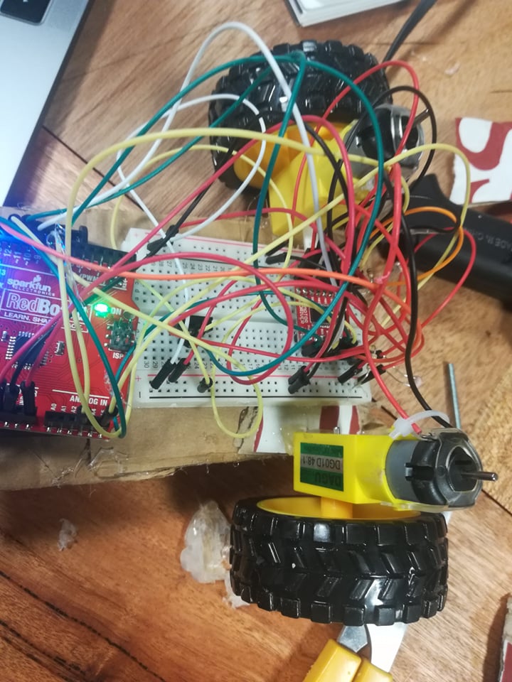
My initial plan for my midterm project was to produce a vehicle that would behave differently depending on how far it was from an object that is in its way. However, Aaron gave me a brilliant idea, which was to have a look at Braitenberg Vehicles, vehicles that would behave differently depending on its distance from light. This solved one of the biggest problems with my initial idea, because the Braitenberg vehicle would allow for greater interaction with users, allowing people to use flashlights on their phone to navigate the vehicle.
My initial prototype was made of cardboard, however, this was structurally very weak and the right wheel would constantly fall off after prolonged movement. The vehicle was also lopsided, with the front being much lower to the ground than the back of the vehicle. This was not aesthetically pleasing and it resulted in some performance issues.
So I instead decided to use wood for the vehicle, which provides a more solid foundation, and solved the issue of the tilted vehicle. For the program itself, I ran an analogRead on the photoresistors positioned at the front of the vehicle, which would determine the speed of the wheels when exposed to varying light levels. This was effective at first, and my vehicle ran smoothly, however, for some reason, one photoresistor was getting much higher read values than the other. Despite trying to debug this and rewire the circuit, I decided to somewhat hardcode the machine. This actually turned out to be more effective, allowing the vehicle to be more attracted to light when the light in the environment was higher. I am sure that my code could have been more efficient.
Here is a video of the vehicle running in a dark room:
I also created a light-fearing version of the vehicle by changing the code by flipping the values for the wheel movement speeds. The vehicle does not work as well as the light-loving version, especially in environments that are moderately lit.
Here is the code for the light-loving version of the vehicle
const int pwma = 11 ;
const int in_1 = 13 ;
const int in_2 = 12 ;
//first wheel ^
const int pwmb = 10 ;
const int in_3= 8 ;
const int in_4 = 9 ;
//first wheel ^

const int photo1 = A4;
const int photo2 = A5;

int direct = 0;
int direct2 = 0;
void setup() {
  // put your setup code here, to run once:
   pinMode(pwma,OUTPUT) ; //we have to set PWM pin as output
   pinMode(pwmb,OUTPUT) ; //we have to set PWM pin as output
   pinMode(in_1,OUTPUT) ; //Logic pins are also set as output
   pinMode(in_2,OUTPUT) ;
   pinMode(in_3,OUTPUT) ; //Logic pins are also set as output
   pinMode(in_4,OUTPUT) ;
   Serial.begin(9600);
}

void loop() {
  // put your main code here, to run repeatedly:
   direct = random(0, 1);
   direct2 = (direct + 1) % 2;
   int photoOneValue = map(analogRead(A4), 0, 1023, 0, 255);
   int photoTwoValue = map(analogRead(A5), 0, 1023, 0, 255);
   if (photoTwoValue > 105) {
     digitalWrite(in_1, direct2) ;
     digitalWrite(in_2, direct) ;
     digitalWrite(in_3, direct2) ;
     digitalWrite(in_4, direct) ;
     analogWrite(pwma, 70);
     analogWrite(pwmb, 250);
     Serial.println("1");
} // speed in opposite direction to light
   //previous value was 85 ^

   else if (photoOneValue > 160) {
     digitalWrite(in_1, direct2) ;
     digitalWrite(in_2, direct) ;
     digitalWrite(in_3, direct2) ;
     digitalWrite(in_4, direct) ;
     analogWrite(pwma, 250);
     analogWrite(pwmb, 70);
     Serial.println("2");
   }
   //previous value was 160 ^
   else if (photoTwoValue < 20 && photoOneValue < 80) {
     digitalWrite(in_1, direct2) ;
     digitalWrite(in_2, direct) ;
     digitalWrite(in_3, direct2) ;
     digitalWrite(in_4, direct) ;
     analogWrite(pwma, 110);
     analogWrite(pwmb, 110);
     Serial.println("3");
//constant slow speed when room is dim
 }
  else if (photoTwoValue > 20 && photoOneValue > 80 && photoOneValue < 160 && photoTwoValue < 105) {
     digitalWrite(in_1, direct2) ;
     digitalWrite(in_2, direct) ;
     digitalWrite(in_3, direct2) ;
     digitalWrite(in_4, direct) ;
     analogWrite(pwma, photoOneValue + 20);
     analogWrite(pwmb, photoTwoValue + 60);
     Serial.println("4");
//environment not dim, but light not sensitive enough to activate the two if statements on top, allows vehicle to move faster towards light/
  }
}
And below is the code for the “light-fearing” version of the vehicle:
const int pwma = 11 ;
const int in_1 = 13 ;
const int in_2 = 12 ;

const int pwmb = 10 ;
const int in_3= 8 ;
const int in_4 = 9 ;

const int photo1 = A4;
const int photo2 = A5;

int direct = 0;
int direct2 = 0;
void setup() {
  // put your setup code here, to run once:
   pinMode(pwma,OUTPUT) ; //we have to set PWM pin as output
   pinMode(pwmb,OUTPUT) ; //we have to set PWM pin as output

   pinMode(in_1,OUTPUT) ; //Logic pins are also set as output
   pinMode(in_2,OUTPUT) ;
   pinMode(in_3,OUTPUT) ; //Logic pins are also set as output
   pinMode(in_4,OUTPUT) ;
   Serial.begin(9600);
}

void loop() {
  // put your main code here, to run repeatedly:
   direct = random(0, 1);
   direct2 = (direct + 1) % 2;
   int photoOneValue = map(analogRead(A4), 0, 1023, 0, 255);
   int photoTwoValue = map(analogRead(A5), 0, 1023, 0, 255);
   if (photoTwoValue > 105) {
     digitalWrite(in_1, direct2) ;
     digitalWrite(in_2, direct) ;
     digitalWrite(in_3, direct2) ;
     digitalWrite(in_4, direct) ;
     analogWrite(pwma, 250);
     analogWrite(pwmb, 70);
     Serial.println("1");
}
   //previous value was 85 ^

   else if (photoOneValue > 160) {
     digitalWrite(in_1, direct2) ;
     digitalWrite(in_2, direct) ;
     digitalWrite(in_3, direct2) ;
     digitalWrite(in_4, direct) ;
     analogWrite(pwma, 70);
     analogWrite(pwmb, 250);
     Serial.println("2");
   }
   //previous value was 160 ^
   else if (photoTwoValue < 20 && photoOneValue < 80) {
     digitalWrite(in_1, direct2) ;
     digitalWrite(in_2, direct) ;
     digitalWrite(in_3, direct2) ;
     digitalWrite(in_4, direct) ;
     analogWrite(pwma, 110);
     analogWrite(pwmb, 110);
     Serial.println("3");

 }
  else if (photoTwoValue > 20 && photoOneValue > 80 && photoOneValue < 160 && photoTwoValue < 105) {
     digitalWrite(in_1, direct2) ;
     digitalWrite(in_2, direct) ;
     digitalWrite(in_3, direct2) ;
     digitalWrite(in_4, direct) ;
     analogWrite(pwma, photoTwoValue + 60);
     analogWrite(pwmb, photoOneValue + 20);
     Serial.println("4");
  }
}
This was a very fun post to read because I felt like it was a great “wiki” page for Interactive Media undergraduate projects. I think that this provides me with a very good starting point for brainstorming possible projects in the future, especially for me final project. The author also gives helpful tips for “optimizing” the projects, and making them as interactive and effective as possible. I also found the author’s second paragraph to be interesting and inspiring. I encountered this problem of originality early on in the course, when I would see project ideas online or from former classes. Not that I ever copied them, but taking inspiration from technical or creative elements from these projects would inevitably result in my own personal twists to the project, allowing me to create my own original output. This is why the author’s point on originality truly resonated with me, and I think I will be less afraid to seek inspiration from others’ work.
I really enjoyed reading this article, and throughout reading it my mind could not help but think about this in the context of other arts forms, like paintings, or especially music, my favorite art form that is such a huge part of my life. Music is often something that promotes self-reflection for me and I try to find meaning in whatever I listen to. I constantly wonder about why musicians sometimes decide not to comment on the meanings of their songs, and how my interpretation of the song might change if I know the artist’s intended meaning for the music they created, rather than just my own interpretations of the music.
Linking this back to interactive art, I have a hard time commenting on this, mostly because I think of interactive art as something that is playful, rather than something that conveys a deeper meaning. Because of this, I am not really sure what to think about this text. For instance, websites and video games are examples of interactive art, and I think that these can and do convey a deeper meaning, but this must be spelled out by the creators of the product. As for interactive art installations I have seen, I think it would be beneficial for the people interacting with the project to not know the true intentions of the artists so that they are able to freely interact with the product (if the artist wanted genuine interactions).
In this reading, the author shows various ways of already established methods of Physical Computing. They encourage the reader that instead of dismissing working on ideas that were already done, they should work on improving them and developing them more than the original creator of the concept. What I like about this, in particular, is that it hints on the idea of innovation not being “brand new” but rather “new elements in existing things”.
For my midterm assignment, I decided to build a machine able to automatically play the piano at the same time that the user is playing the guitar. I called this machine” The Force Piano”. This machine functions in the following way. The guitar functions as a switch, so when the user plays it activate three servos and each servo moves a stylus able to touch the touchscreen of an Ipad. In the iPad, an application that simulates a piano was downloaded. Through this application, the stylus interacts with the piano application.
The building process of this machine was the following. First, an Ipad Mini and Arduino breadboards were stuck with tape to a big piece of wood. Then the three servos were connected to the breadboards and a code was created that allows the servos to move once from angle 90 to 180 and vice-versa every time that a switch is turned on(The code was attached at the end of this post). Next, three stylus were created using aluminum, cotton swabs, and water. The plastic stick of the cotton swabs was surrounded with aluminum and the aluminum was positioned to slightly touch the cotton tip, then, the cotton tip was submerged into water (water allows electricity to flow electricity to the touchscreen of the iPad) and each one was connected to an alligator cable coming from Power from the breadboard. After building the stylus, these were attached to the servos using hot glue and then the servos were stuck to the piece of wood, considering the position of the notes F4, A4 and C5 in the piano app of the iPad. The switches to activate the servos were build using the metal strings of the guitars. Three alligators cables were attached to the 5th, 4th and 3rd string of the guitar and these alligators were connected to ground in the breadboard. Then an alligator cable coming from power was connected to a metal pick (every time the pick touches the string the circuit is closed). And finally, the guitar was played to test that the servo moved with the angle needed to touch the correct note of the piano.
The biggest challenges in this assignment were figuring out how to create a stylus. My original idea was made a drum with wood and hit it with drumsticks to create sound, but then, I thought it was going to be cooler to make the servo to play the song with me, and as It was impossible to use a real piano, I improvised and decided to use my old IPad mini. The challenge was that I thought that I was going to be able to interact with the touchscreen with any material. But, It did not take long until I realized that it was not that simple. So, after doing some research, I learned that, in order to interact with a touchscreen, I needed to make electricity flow through the material. Hence, my first prototype of a stylus it only had aluminum, but when I did the testing I realize that it only interacted with the touch screen 1 out 3 times, that’s why I decided to use softer material pour water on it.. The other challenge was positioning and finding the angles for the servos by trial and error. To finally, figure it out I needed to rebuild several times the servos-stylus prototypes.