
I spent a while refreshing on the coding we learned the other day, and found the part that involves sensors most intriguing. I tried analog input with the potentiometer, flex sensor, and photocell. I also asked Scott about the RGB LED and tried it with switches on my board. But all this review work didn’t really give me an idea what to do for the assignment. So I looked closely at the shelf full of electric parts, and found this magic stuff:
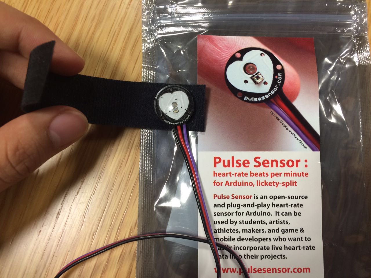
First I thought it is super complex because it has a few parts that I don’t understand. But after I searched for it online it turned out to be pretty straightforwardly designed. Basically I just used 1) the pulse sensor main board, its cable and headers, 2) the transparent Stickers that protects the board surface. More info about the sensor itself could be found here.
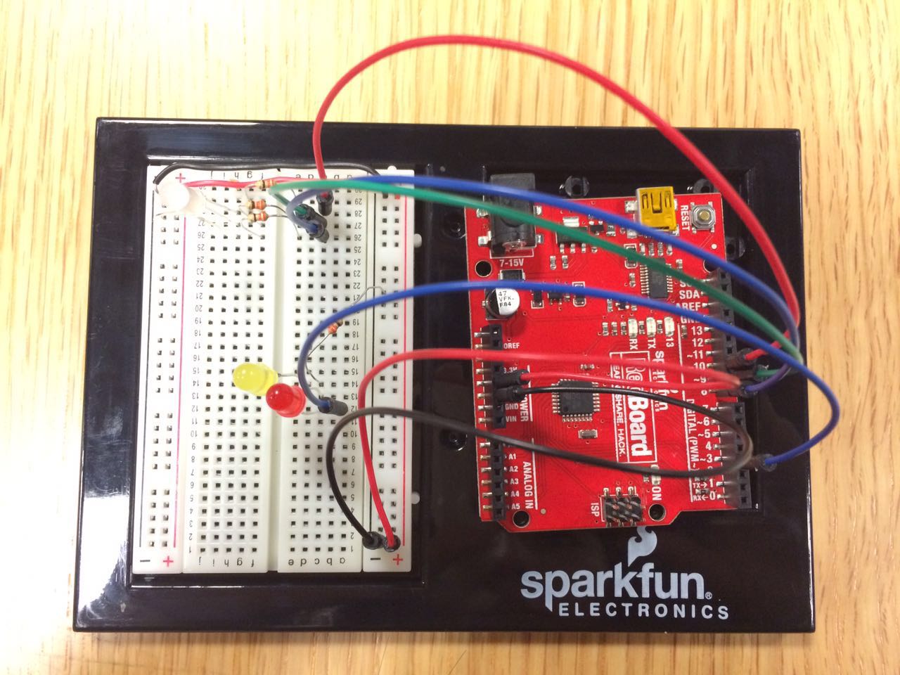
So I connected the pulse sensor to the breadboard to control a yellow, a red and a RGB LED. When the code is uploaded without the sensor at work, the purple light would be on( Analog Input ranging from 0 to 300); when the sensor detected my heartbeat, the yellow and red LEDs would blink with the interval of the analog input of the pulse sensor( usually 400-700); and when I detached the sensor and put it down on the surface of my laptop, the RGB would light up as another color( The funny thing is, I’m not sure about the color. In my code it’s the mix of red and green, which should’ve been yellow, but it was actually more blueish than anything else. Is the RGB inaccurate?). The way I determined the analog input range was purely by experiment. Thanks to Rong Sang, who did something similar with her assignment. I found that setting the range was pretty useful though not always reliable. Another concern is that the sensor is not so accurate as well. The lights would often just go wild without my touching the sensor at all.
The code looks like this:
const int myLED = 3;
const int BlueLight = 8;
const int GreenLight = 9;
const int RedLight = 10;
const int PulseSensor = A0;
int sensorVal;

void setup() {
  pinMode(myLED, OUTPUT);
  pinMode(BlueLight, OUTPUT);
  pinMode(GreenLight, OUTPUT);
  pinMode(RedLight, OUTPUT);
  Serial.begin(9600);
}

void loop() {
  sensorVal = analogRead(PulseSensor);
  int delayTime;
  delayTime = sensorVal;

  if(sensorVal >= 0 && sensorVal <= 300) {
  digitalWrite(BlueLight, HIGH);
  digitalWrite(RedLight, HIGH);
  delay(delayTime);
  digitalWrite(BlueLight, LOW);
  digitalWrite(RedLight, LOW);

  } else if(sensorVal > 400 && sensorVal <= 700) {
  digitalWrite(myLED, HIGH);
  delay(delayTime);
  digitalWrite(myLED, LOW);
  delay(delayTime);

  } else if( sensorVal >= 900) {
  digitalWrite(GreenLight, HIGH);
  digitalWrite(RedLight, HIGH);
  delay(delayTime);
  digitalWrite(GreenLight, LOW);
  digitalWrite(RedLight, LOW);
  }

 Serial.println(sensorVal);
}
And the video of what I call the LightPulb is here: