Concept & Usage: My idea was to build a distance-sensitive security system. The system is designed to be sensitive to distance, using the HC-SR04 ultrasonic sensor paired with an Arduino board to trigger an audible alarm. The closer the object is to the sensor, the faster the alarm—or buzzer—will beep, which serves as an intuitive indicator of proximity.
The ultrasonic sensor-based alarm acts not only as a simple security device but can also be an interactive element for various applications. By emitting ultrasonic waves, the sensor can determine the distance to an object based on the time it takes for the waves to return. In the context of security, this setup can detect potential intruders or unauthorized access by sensing motion within a predefined range.
The versatility of the alarm allows it to be adapted for different purposes, such as:
Intruder detection for personal properties, alerting homeowners to possible trespassers
Industrial safety, where restricted areas can be monitored to ensure personnel safety
Public events, to manage crowd control and prevent attendees from accessing sensitive areas
Implementation:
When the system senses an object within a specified distance (less than 50 cm in your code), it activates the buzzer. The alarm’s operation is controlled by the code which defines the pins for the sensor and the buzzer, measures the distance by calculating the time interval of the echo’s return, and dynamically adjusts the beeping speed based on this distance.
trigPin and echoPin are defined for sending and receiving the ultrasonic signals.
buzzer is defined for the alarm sound.
In the loop function, the program triggers the ultrasonic sensor and listens for the echo. The distance is calculated based on the time it takes for the echo to return.
The new_delay is calculated based on the measured distance. The closer the object, the smaller the delay, resulting in a faster beep.
The buzzer is activated if the object is within 50 cm of the sensor, with the beeping speed proportional to the object’s proximity.
References:
I used several Youtube tutorials for executing the project using the tools.
Exercise 1: make something that uses only one sensor on arduino and makes the ellipse in p5 move on the horizontal axis, in the middle of the screen, and nothing on arduino is controlled by p5
Using the ultrasound sensor, the circle moves horizontally on the canvas.
Exercise 2: make something that controls the LED brightness from p5.
The LED brightness is controlled by the vertical distance of MouseY and the top of the screen. The higher the distance the brighter the LED. So, when the user drags the ellipse from the top to the bottom of the canvas, the brightness of the LED increases proportionally and vice versa.
//exercise 2, week 11, controlling the brightness of LED with p5.js
//Diana and Buka
// Output:
// - 5 - LED

const int ledPin = 5; //the LED pin is at 5

void setup() {
 // Start serial communication so we can send data
 // over the USB connection to our p5js sketch
 Serial.begin(9600);
 // use the builtin LED as a status output.
 pinMode(LED_BUILTIN, OUTPUT);
 pinMode(ledPin, OUTPUT);

 // Start the handshake
 while (Serial.available() <= 0) {
   digitalWrite(LED_BUILTIN, HIGH); // on/blink while waiting for serial data
   Serial.println("0"); // send a starting message
   delay(300); // wait 1/3 second
   digitalWrite(LED_BUILTIN, LOW);
   delay(50);
 }
}

void loop() {
 // Wait for data from p5 before doing something
 while (Serial.available()) {
   digitalWrite(LED_BUILTIN, HIGH); // LED on while receiving data
   // reading the integer value, confirming that the next character is a new line and sending confirmation 1
   int brightness = Serial.parseInt();
   if (Serial.read() == '\n') {
     delay(5);
     Serial.println("1");
   }

   // LED brightness is set accordingly
   analogWrite(ledPin, brightness);
 }
 digitalWrite(LED_BUILTIN, LOW);
}
Exercise 3: take the gravity wind example and make it so every time the ball bounces one led lights up and then turns off, and you can control the wind from one analog sensor
The LED is on when the ball is on the ground / hits the ground when bouncing. And the ball can be controlled by the potentiometer to move left and right.
const int LED_PIN = 3;
const int SENSOR_PIN = A2;


void setup() {
Serial.begin(9600);
pinMode(LED_PIN, OUTPUT);


// Test the LED
digitalWrite(LED_PIN, HIGH);
delay(500);
digitalWrite(LED_PIN, LOW);
}


void loop() {
int p_value = analogRead(SENSOR_PIN); // read from the potentiometer
int move = map(p_value, 0, 1023, -1, 2); // map the value to -1, 0, and 1
Serial.println(move);


if (Serial.available() > 0) {
// read from p5.js
int touch = Serial.parseInt();
// set the LED command
if (touch == 1) {
digitalWrite(LED_PIN, HIGH);
} else {
digitalWrite(LED_PIN, LOW);
}
}
}
Concept:
Neuro-jump is an interactive game that aims to challenge its users and encourage them to think about using their body as an interaction tool that allows them to interact with technology. Neuro-jump detects the user’s EMG-muscle signals and allows them to control the jumping Alien cowboy by flexing their bicep muscle
This game is a critique to the status quo of video games and technology in general and an invitation to steer away from using the basic interactive tools such us touch screens and hand held items, and to think about the possibility of employing different techniques.
User testing:
Throughout the process of developing the game I have tried different settings and techniques. I have noticed that some people do very well whereas others struggle to play it. After multiple tests I figured out the best level of difficulty that is not too challenging but not too boring at this same time. I also implemented a slider that allows the users to change the height of the jump of the alien thus making the game easier.
Implementation:
I have used P5 and Arduino to link the EMG signal detecting electrodes with the P5 side of the game. Setting the serial connection was not a very big challenge for me as I made sure only the necessary data will be ent form the Arduino to the computer which will make the user interaction instant and very fast and effective. I have also used the brain-shield gadget that allowed me to detect the EMG signal and transition them into digital data.
The game allows the user to both jump the incoming obstacles by flexing their hand but to also shoot the harmful birds by pressing the space Bar.
For the Arduino code I have used the original script that came with the hardware but I had to change and alter it to make it send the strength signal and use it in the length.
Future improvements and reflections:
I would like to implement the strength of the flex in the game and maybe make the jump or the attack depend on the strength of the flex. I would also like to add other tools that would allow the game to be played by two players instead of one, and maybe add another character and make the game a competitive. I would also like to create a “button-free” game the users can manipulate without the use of their hands but just their movement, facial expression or body position. I want to experiment mare with Interactivity and allow the users to be creative and have a fun time without the need of buttons or touch screens. For Neuro-Jump I would like to implement a program that detects facial gesture or body tracking that would allow the user the control the character.
P5:
Arduino code:
/*
* --------------------------------------------------------------------------------------
* Code monitors amplitude of EMG envelope, displays EMG strength on LED bar and controls
* robotic gripper by controlling servo motor.
* --------------------------------------------------------------------------------------
*/

#include <Servo.h>
#define GRIPPER_STATE_BUTTON_PIN 4          //pin for button that switches defult state
                                            //of the gripper (opened/closed)
#define SERVO_PIN 2                         //pin for servo motor
#define SENSITIVITY_BUTTON_PIN 7            //pin for button that selects sesitivity
#define NUM_LED 6                           //number of LEDs in LED bar
#define GRIPPER_MINIMUM_STEP 5              //5 degree dead zone (used to avoid
                                            //aiming oscilation)
#define OPEN_MODE 1                         //default gripper state is opened
#define CLOSED_MODE 2                       //default gripper state is closed
#define MINIMUM_SERVO_UPDATE_TIME 100       //update servo position every 100ms
#define Max_EMG_LED 3


Servo Gripper;                              //servo for gripper
byte ledPins[] = {8, 9, 10, 11, 12, 13};    //pins for LEDs in LED bar

//EMG saturation values (when EMG reaches this value
//the gripper will be fully opened/closed)
int sensitivities[] = {200, 350, 520, 680, 840, 1000};
int lastSensitivitiesIndex = 2;             //set initial sensitivity index

int emgSaturationValue = 0;                 //selected sensitivity/EMG saturation value
int analogReadings;                         //measured value for EMG
byte ledbarHeight = 0;                      //temporary variable for led bar height

unsigned long oldTime = 0;                  //timestamp of last servo angle update (ms)
int oldDegrees = 0;                         //old value of angle for servo
int newDegree;                              //new value of angle for servo

unsigned long debouncerTimer = 0;           //timer for button debouncer
int gripperStateButtonValue = 0;            //variable that stores state of button
int userReleasedButton = 1;                 //flag that is used to avoid multiple
                                            //button events when user holds button

int currentFunctionality = OPEN_MODE;       //current default position of claw


//-----------------------------------------------------------------------------------
//   Setup servo, inputs and outputs
// ----------------------------------------------------------------------------------
void setup(){

  Serial.begin(9600);
    //init servo
    Gripper.attach(SERVO_PIN);

    //init button pins to input
    pinMode(GRIPPER_STATE_BUTTON_PIN, INPUT);
    pinMode(SENSITIVITY_BUTTON_PIN, INPUT);

    //initialize all LED pins to output
    for(int i = 0; i < NUM_LED; i++){
        pinMode(ledPins[i], OUTPUT);
    }

    //get current sensitivity
    emgSaturationValue = sensitivities[lastSensitivitiesIndex];
}


//-----------------------------------------------------------------------------------
//   Main loop
//
//   - Checks state of sesitivity button
//   - Checks state of default-gripper-state button
//   - Measure EMG
//   - Shows EMG strength on LED bar
//   - Sets angle of servo based on EMG strength and current mode (open/closed)
// ----------------------------------------------------------------------------------
void loop()
{

    //-----------------------  Switch sensitivity ------------------------------------

    //check if button is pressed (HIGH)
    if (digitalRead(SENSITIVITY_BUTTON_PIN))
    {
        //turn off all the LEDs in LED bar
        for(int j = 0; j < NUM_LED; j++)
        {
            digitalWrite(ledPins[j], LOW);
        }

        //increment sensitivity index
        lastSensitivitiesIndex++;
        if(lastSensitivitiesIndex==NUM_LED)
        {
            lastSensitivitiesIndex = 0;
        }

        //get current sensitivity value
        emgSaturationValue = sensitivities[lastSensitivitiesIndex];

        //light up LED at lastSensitivitiesIndex position for visual feedback
        digitalWrite(ledPins[lastSensitivitiesIndex], HIGH);

        //wait user to release button
        while (digitalRead(SENSITIVITY_BUTTON_PIN))
        {
            delay(10);
        }
        //whait a bit more so that LED light feedback is always visible
        delay(100);
    }


    //----------------------------  Switch gripper default position open/close ---------

    //check if enough time has passed for button contact to settle down
    if((millis() - debouncerTimer) > 50)
    {
        gripperStateButtonValue = digitalRead(GRIPPER_STATE_BUTTON_PIN);
        //if button is pressed
        if(gripperStateButtonValue == HIGH)
        {
            //if last time we checked button was not pressed
            if(userReleasedButton)
            {
                debouncerTimer = millis();
                //block button events untill user releases it
                userReleasedButton = 0;

                //toggle operation mode
                if(currentFunctionality == OPEN_MODE)
                {
                    currentFunctionality = CLOSED_MODE;
                }
                else
                {
                    currentFunctionality = OPEN_MODE;
                }
            }
         }
         else
         {
            userReleasedButton = 1;
         }
    }


    //-----------------------------  Measure EMG ---------------------------------------

    analogReadings = analogRead(A0);//read EMG value from analog input A0


    //---------------------- Show EMG strength on LED ----------------------------------

    //turn OFF all LEDs on LED bar
    for(int j = 0; j < NUM_LED; j++)
    {
        digitalWrite(ledPins[j], LOW);
    }

    //calculate what LEDs should be turned ON on the LED bar
    analogReadings= constrain(analogReadings, 30, emgSaturationValue);
    ledbarHeight = map(analogReadings, 30, emgSaturationValue, 0, NUM_LED);

    //turn ON LEDs on the LED bar
    for(int k = 0; k < ledbarHeight; k++)
    {
        digitalWrite(ledPins[k], HIGH);
    }

  //-------------------- Send EMG strength data over serial -----------------------
  Serial.println(analogReadings);


    //-------------------- Drive Claw according to EMG strength -----------------------

    //set new angle if enough time passed
    if (millis() - oldTime > MINIMUM_SERVO_UPDATE_TIME)
    {
        //calculate new angle for servo
        if(currentFunctionality == OPEN_MODE)
        {
            analogReadings = constrain(analogReadings, 40, emgSaturationValue);
            newDegree = map(analogReadings, 40 ,emgSaturationValue, 190, 105);
        }
        else
        {
            analogReadings = constrain(analogReadings, 120, emgSaturationValue);
            newDegree = map(analogReadings, 120 ,emgSaturationValue, 105, 190);
        }

        //check if we are in servo dead zone
        if(abs(newDegree-oldDegrees) > GRIPPER_MINIMUM_STEP)
        {
             //set new servo angle
             Gripper.write(newDegree);
        }
        oldTime = millis();
        oldDegrees = newDegree;
    }
}
The concept is pretty simple make an LED that reminds you if you forgot to grab something before leaving your room. The light will stay on until you picked up all the things you need before going outside. Only when you picked up everything it will turn off.
Circuit
1 LED, 5 jumper wires, a breadboard, an Arduino board, and 1 220-Ohm resistor were used. The switch makes use of a simple circuit that introduces an opened circuit when at least one item is still on the table and a closed circuit when all items are taken out.
Reflection
After building this switch, I gained some practical experience in working with an Arduino board and various electronic components. I learned how to connect different components together on a breadboard and how to use jumper wires to make connections between them. I also learned how to use a resistor to limit the current flowing through the LED.
I learned about the concept of switches and how they can be used to turn electrical circuits on and off. During the process of building the switch, I encountered some difficulties or errors, and I had to use my problem-solving skills to identify and fix the issues. This taught me the importance of troubleshooting and problem-solving when building electronic circuits.
Finally, successfully building the switch and seeing it work gave me a sense of satisfaction and accomplishment. It also gave me some inspiration for further projects or ideas for using switches and other electronic components in creative ways.
Overall, building this switch was a valuable learning experience that helped me develop my skills in electronics and problem-solving.
For this project, I wanted to make a fun switch, like the mustache one. So, I made two stick/wire figures that held aluminum foil in their hands and when they high five/fist bump, the bulb lights up. The figures are attached to my shoes so I move them using my feet. While this is not a practical switch, I really enjoyed being creative with it!
Future Improvements
Another thing that can be tried later is that instead of making their hands meet, I can attach the wires directly to my shoes so whenever the shoes touch, the bulb will light up.
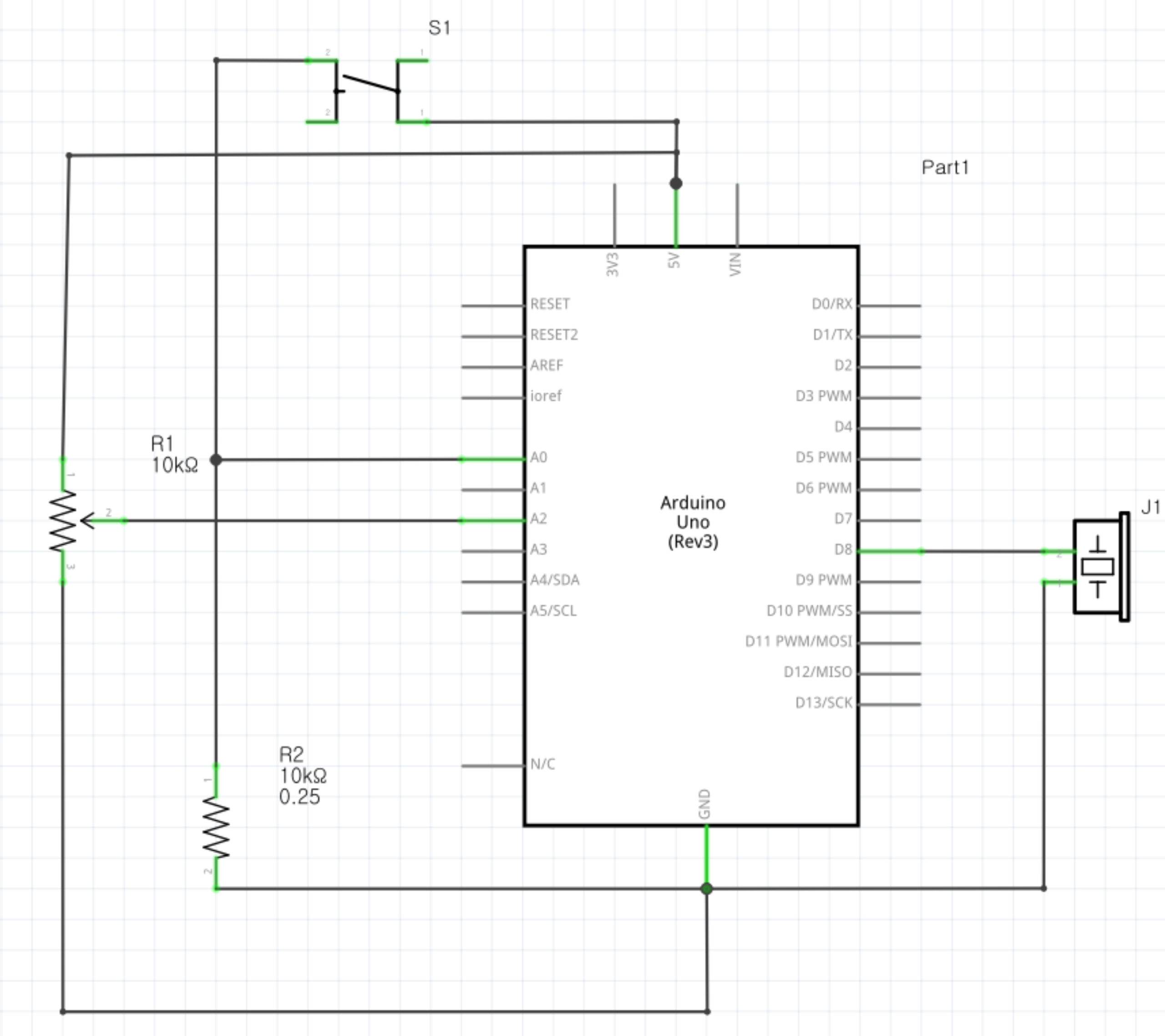
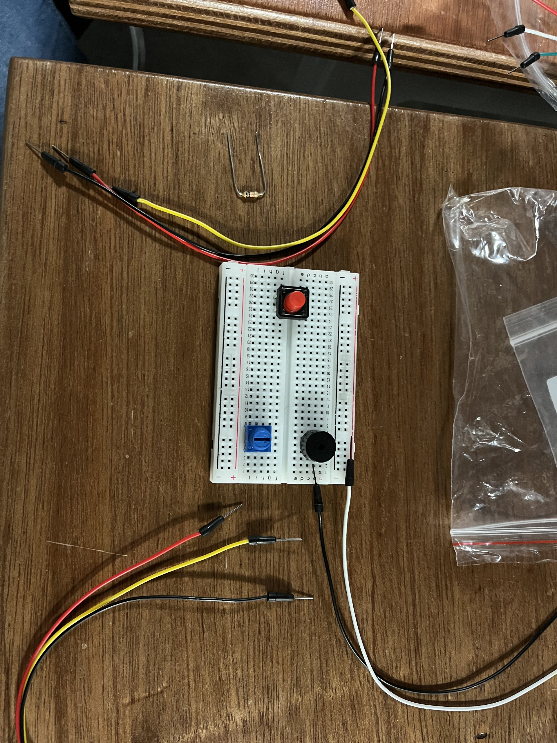
To be frank, we both didn’t really have a mind-blowing, creative inspiration when we got started on this project, which is why we decided to create something that’s simple but also making sure that it will leave enough room for user to be creative with it on our behalf. The idea that we had was to create an instrument that is able to be controlled by the user, such as its beats, pitch, etc., and it consisted of one digital sensor (switch), one analog sensor (potentiometer), and a Piezo speaker, along with the according wires that were needed. Here’s the picture of our initial state that we began with, along with the schematic:
Process/Coding:
While building the circuit itself was fairly easy and efficient since it was just a matter of connecting the wires into the respective places, the coding process was a little bit more complicated as we ran into a few obstacles:
Initially, the turn-off function of the switch wasn’t working — this was because of the delay time, so we realized that we had to press on the switch for a while instead of just pressing lightly.
We also had to adjust the tone range of our “instrument” — initially it was around 5000, but we later made it to 2000 so that it doesn’t hurt our ears as much even when we turn it up to the maximum tone.
Sometimes, the instrument won’t turn off at all even when we pressed down on the switch with enough strength and time; this was due to a small error in the code.
But after a few trials and errors, we were able to fulfill our initial vision for our instrument by controlling both the beat and the pitch either simultaneously or separately.
There was one aspect of the code that was still slightly flawed when we went back to review it, but the final product seemed to work fine despite it so we kept it, which is shown here:
// the loop routine runs over and over again forever:
void loop() {
  // read values from potentiometer
  int sensorValue = analogRead(potentiometer)/5*5;  // <- to mitigate unintended frequency change caused by the sensor
  delay(1);  // delay in between reads for stability
  frequency = map(sensorValue,0,1024,0,2000); // limit frequency range to avoid unpleasant sound

  manageOutputPattern(); // determines which sound mode will be played

  if (!!outputPattern) { // if outputPattern is 0, idle(). Else make sound.
    makeSound();
  } else {
    idle();
  }

  // was supposed to do something similar to x 1.3 delay in "ToneMelody" example
  // But this is flawed as noteDuration is less than (1300-1000) when BPS is >2.
  // However, the product seems to work fine so will not correct this issue.
  counter = (counter + 1) % 1300;
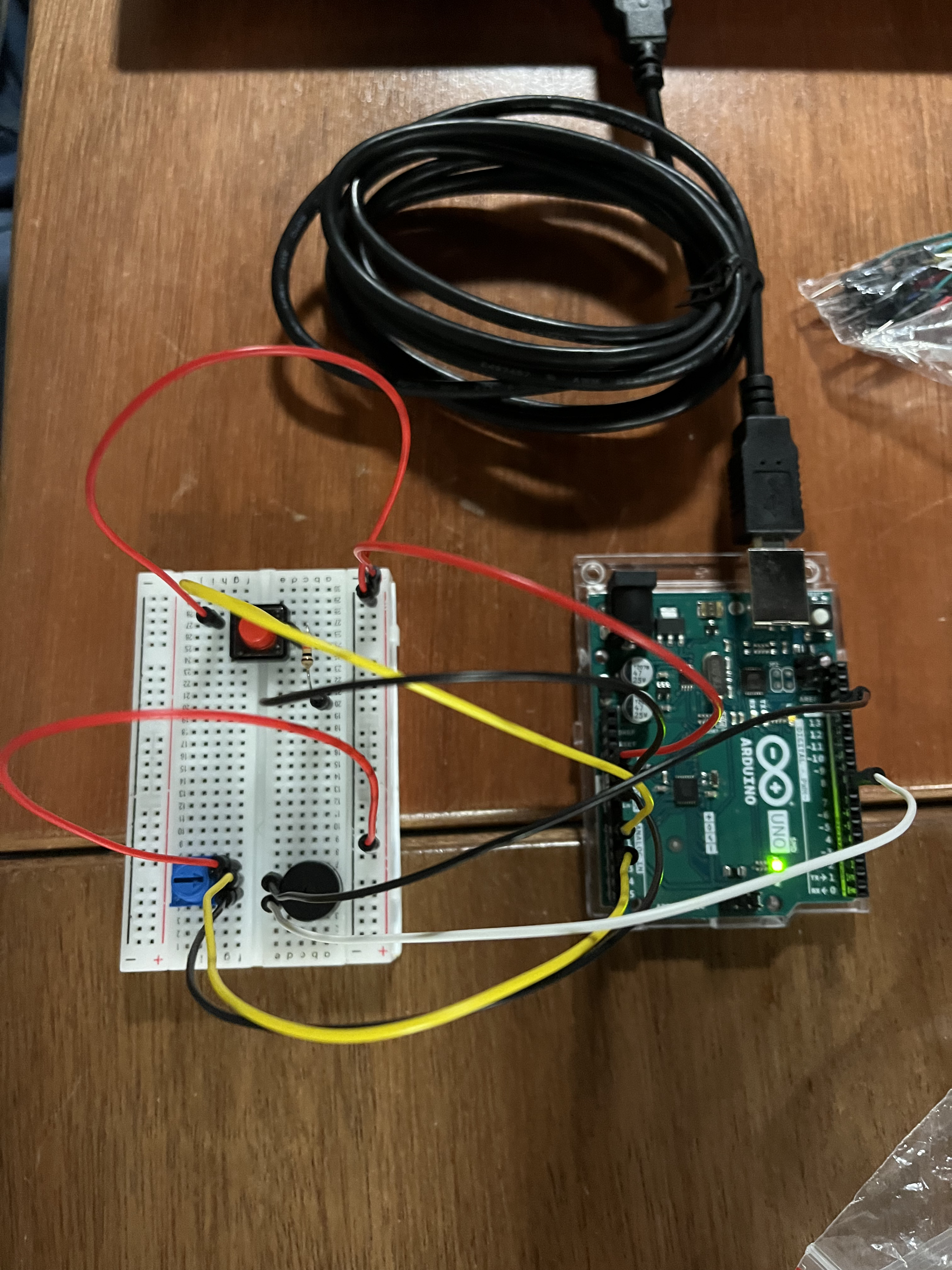
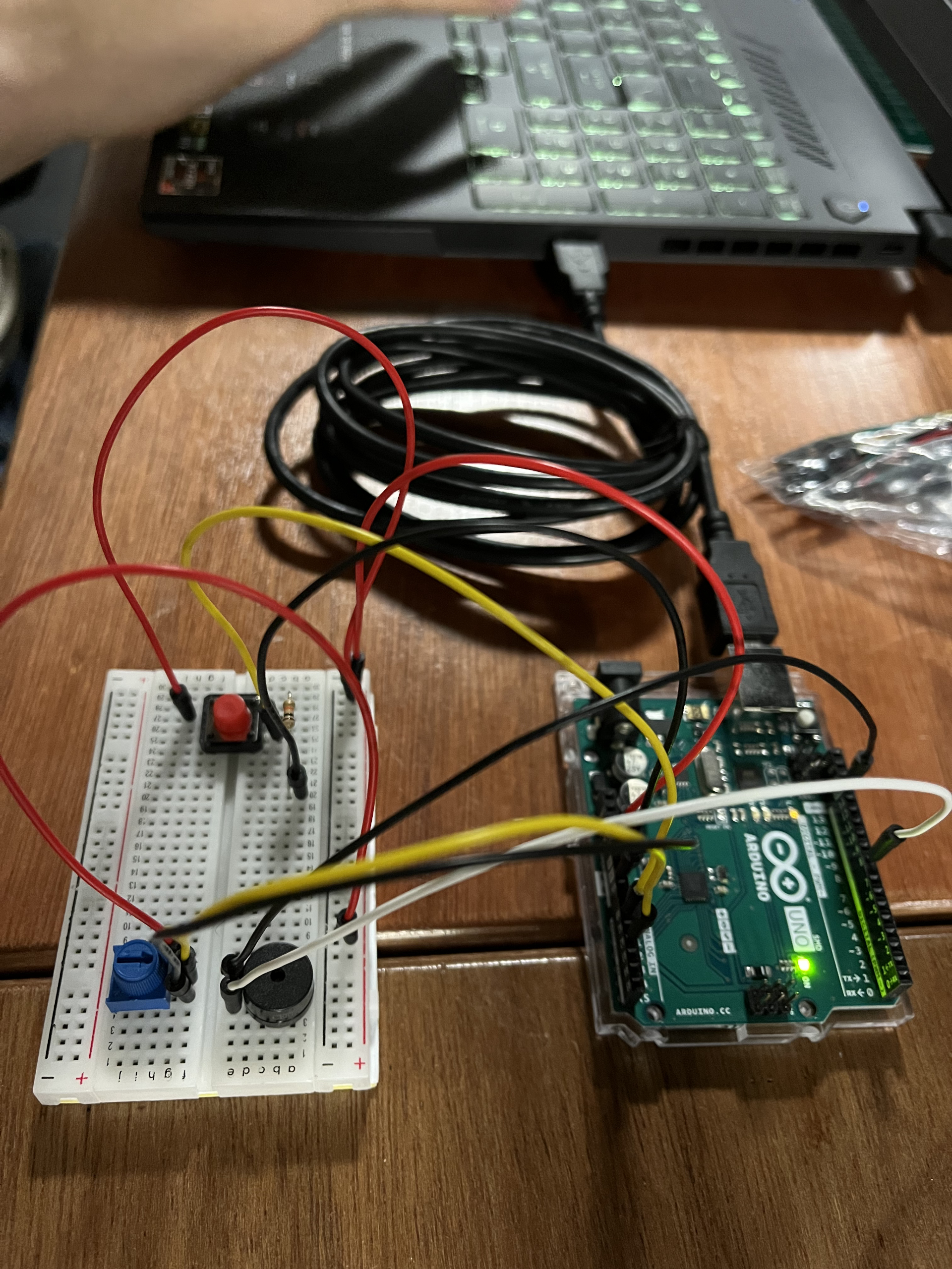
To see the entire code, click here. Final Product:
Here’s what the final product looked like:
Here’s a brief instruction on how to use the instrument:
When you press on the switch button, the Piezo buzzer will start making sounds.
You can use the potentiometer to control the pitch/tone of the sound and you can use the switch button to control the beat length of each sound. Mind the fact that each time you press on the switch button, the beats will get faster and faster. There will be 5 different beat speed offered.
By pressing the switch button for the 6th time, you will be able to turn off the instrument completely.
…and here’s the video of it running:
Reflection:
Despite some minor hiccups that we’ve faced during the making process, this project was actually pretty manageable and simpler than we thought it’d be! It was exciting to hear how the sound changed as we adjusted the potentiometer/pressed the switch button to create a melody. Potentially creating a song or playing an already existing one by using this instrument that we made will be really fun, and we’re proud of the final product that we ended up with!
So far, we have added extra an obstacle detection system using the ultrasonic sensor and a boost in maneuverability to the car. Earlier, the car would only curve slightly when moving left and right. Now, it stays in place and adjusts directions before moving forward or backward.
After user testing, we have concluded that the car works as it was intended to. The ultrasonic sensor adds the automatic breaking functionality that we wanted to add initially. There are a few problems with the sensor though.
Furthermore, we have also figured out how to use the XBee shield to establish wireless connection between two computers. Although, we ran into a problem here too. We will need to book office hours with the Professor to figure this out.
Challenges
As observed in the video shared above, the car moves forward in intervals. This only happens when the code for the motion sensor is uploaded. We have deduced that this must be because of all the system delays associated with the working of the ultrasonic sensor. Furthermore, we cannot figure out how to connect the Xbee shield to p5js. We figured out how to connect the two components of the shield together, but we cannot properly connect it to p5js and then to Arduino. Solving this issue will mark the end of our project.
When I was younger, I was OBSESSED with the Backyardigans. Maybe I still am a little 👀 . I watched it daily on Discovery Kids at 7:30pm before going to bed, and vividly remember there being one special two-part episode: Season 2 Episode 15: International Super Spy. (Yes this is the show and episode of that viral song.) I would pray for it to come on every night, and jump arround in joy when they did. For my final project for intro to IM, I am looking forward for constructing an interface similar to the one where Pablo has to dance to save Tasha from the lady in pink. (See Below or HERE if it does not work)
In this interface, Pablo stands on a pad and mimics a screen as it displays a character dancing. His movements are recorded and, if correct, marked in a progress bar. It indicates that he needs to complete the dance to earn a reward. I want to do something similar, where a displayed character can mimic or indicate specific dance moves from a person standing in front.
Idea ⌨️
For this concept, the display will be built with P5.Js, where a simple character, instructions and music will be shown. I would like to project this using one of the vertical projects. Furthermore, Arduino sensors will be used to record the position of the person. I imagine some pressure sensors in the floor to calculate where the user is standing (and with how many feet) , and a camera or infrared sensors to indicate the positions of key body parts (i.e hands, elbows, knees, toes, head). I would ask the person to get into a specific position, and record the difference in movement in a set period of time to determine if the movement is correct or not.
The feedback would mostly be similar to the one shown in the video, with a green progress bar that gets red and makes an error sound when a position is missed. I’d also like to include a reward system built with Arduino motors to give out a price for those of you who know how to dance.
I still want to develop this idea further, as I want to add elements to the design and concept that are mine. Yes, I want the vibe and situation of the Backyardigans, but I also want it to be signed Juanma. Perhaps adding more gimmicks or an extra step to the interface would be cool.
When faced with the use of both analog and digital sensors, my mind initially went to cars. Especially their interface right in front of the steering wheel that indicates fuel, if lights are turned on or off, speed, and many other components. I imagine they must use both, digital and analog circuits, for all these LED’s and indicators. And thus, decided to build my own. Throughout my brainstorm process I was also reminded of Ruta, my favorite card game. In this board game, you need a green light card to signify the car running. A yellow/red light would indicate you could not drive, nor obtain points.
Building Process 🚧:
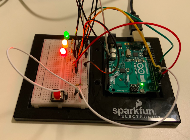
Going off from this concept, I placed three LED’s, a red one, a yellow one, and a green one in the shape of a stoplight. This would be my visualization of the car running or not. I then added three elements that are crucial for driving successfully:
Pressing the Accelerator
Adjusting the Steering Wheel
Turning on the Headlights if it’s dark
With these requirements, I built the following:
A digital circuit for the red light. It is on, only if you press on the red button, which represents the gas pedal.
A circuit with an analog sensor for the yellow LED. It will blink unless the steering wheel, a potentiometer, is oriented towards the right side, in which it will be turned off.
An analog circuit with the Blue LED light. It will light up as per the light it receives from the photosensor.
IF the light received passes a certain threshold, the accelerator is pressed, and the steering wheel is facing the correct way, the green light will turn on, and you will be on your way!
Here is my Code:
const int greenPin = 7;
const int yellowPin = 4;
const int redPin = 2;
const int buttonPin = 3;
const int wheelPin = 8;
const int bluePin = 9;
unsigned long timer = 0;
bool onOff = LOW;

void setup() {
  Serial.begin(9600);
 pinMode(greenPin, OUTPUT);
 pinMode(yellowPin, OUTPUT);
 pinMode(redPin, OUTPUT);
 pinMode(bluePin, OUTPUT);
 pinMode(buttonPin, INPUT);

}

void loop() {
bool redState = digitalRead(redPin);
bool yellowState = digitalRead(yellowPin);

// RED //
byte buttonState = digitalRead(buttonPin);

if (buttonState == HIGH) {
  digitalWrite(redPin, LOW);
} else
{digitalWrite(redPin, HIGH);}
// RED//

//YELLOW//
int wheelValue = analogRead(A0);
int mappedValue = map(wheelValue, 0, 1023, 0, 255);


if (mappedValue > 110 && mappedValue < 140) {
  digitalWrite(yellowPin, LOW);
} else {

 if(millis()>timer){
      onOff = !onOff;
      timer = millis() + 200;
      digitalWrite(yellowPin, onOff);
      }
      }

//YELLOW//


// BLUE //
int lightValue = analogRead(A1);
int mappedLightValue = map(lightValue, 655, 1000, 0, 255);
int constrainedValue = constrain(mappedLightValue, 0, 255);

analogWrite(bluePin, constrainedValue);
//Serial.println(lightValue);
// BLUE //

// GREEN //
if (redState == LOW && yellowState == LOW && mappedValue > 110 && mappedValue < 140 && constrainedValue > 200){

 digitalWrite(greenPin, HIGH);
} else {
  digitalWrite(greenPin, LOW);
  }
// GREEN //

}
Initially, I had the yellow LED to blink at a speed determined by the analog input of the potentiometer. The higher the value, the fastest the blinking. However, this gave the project an unorganized structure and distracted the user from the goal of turning on the car. Thus, I gave it a set value.
Another important thing to note is that during the day, the blue LED will always be turned on. This is intentional, and is used to signify how headlights are only needed at night. If you wish to change this, alter the mappedLightValue variable and make the 655 higher to a threshold of about 950+.
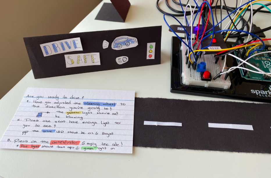
Final Product 🚨:
I am very happy with how Drive Safe turned out. After I completed the circuit, I made some decorations to make it look cleaner and easier to understand. I have tested it multiple times, in multiple scenarios and it seems to work perfectly fine. I also wrote a set of instructions for anyone using it without me.
In the future, I would like to experiment with other type of sensors, and figure out a way to make cables not visible, as they damage the aesthetic quality of the piece a lot.