This assignment was non less than an endeavor in its own. All I had in mind was circles when I started. I thought of them as colliding an getting bigger or something like that. The hardest part was to come up with something which uses loops. Not from the coding end but from the creative one. The it suddenly hit me; draw in itself if a big while TRUE loop. Honestly I still didn’t know what to do about it, but at least I had starting point.
I wanted to add an interactive side to it as well, so the first thing I did was created pointer for the pointer, so that it has visible interactions. I borrowed the monitor frame from my self portrait to add somewhat character to the framing.
The moment I had two circles bouncing off each other. I noticed the the repeating motion. To observe it in detail I wanted to add the trail into it. I had some what trouble doing that because of the monitor underneath, the trail was hidden under it. I asked chatgpt about it. It made me realize that I don;t want my monitor to be draw again and again. So I just put it up in the setup. no I could see their movement.
The most interesting part about it was they never collided if left undisturbed. Because of the movement variables I set. But if it is disturbed by the mouse the kinda stuck in the loop. This discovery is what I am most proud of, I am not sure which part of the code represents it. It randomly reminded me of how it is necessary to go off road to meet people or places that quite possible create the biggest impact in our lives.
I used the https://p5js.org/reference/p5/text/ to write the text. It represents a vague idea I conclude from above about living
lastly the part of code I think is highlight is as follows
x += 1
  if (x % 220 == 0){
  c1 = random(0,255)
  c2 = random(0,255)
  c3 = random(0,255)
  fill(c1,c2,c3)

}
I like this because this where I manipulated the draw loop code to change the circle colors
The Sketch
What I can add to this is. I feel like this is very sketchy. To represent the, I would want to make more calm and smooth
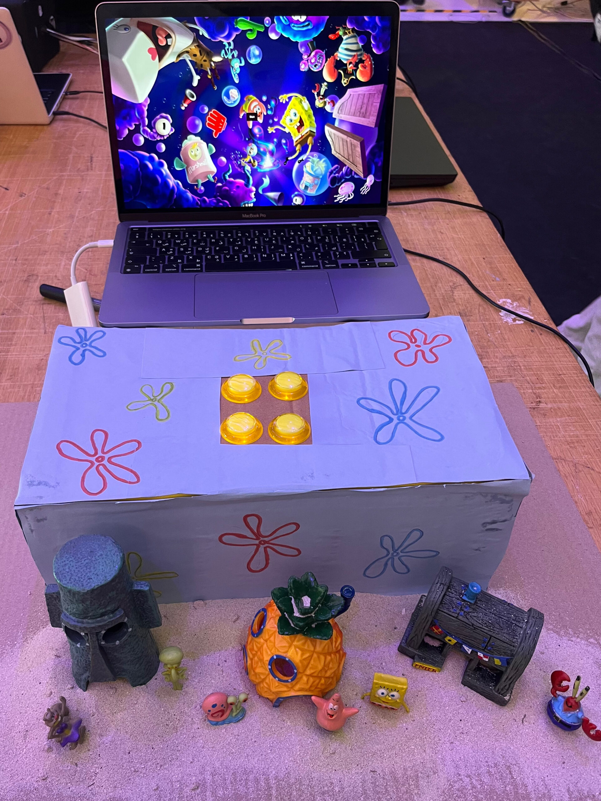
When I look at how F1 drivers train their reflexes, one of the machines inspired me to create this game. However, this game is not to train your reflexes but your memory. Inspired by this, my project, “SpongBlob” aims to enhance users’ color memory skills through an interactive game developed using Arduino and p5.js. This game not only serves as an entertaining experience but also as an educational tool to study color perception and memory. The game is also aimed for kids who are at risk of losing their focus span to the developing social media and short video world, which makes this game a tool for them to gain their focus back. This inspired the SpongeBob theme, so that it is more kid friendly.
Game setup:
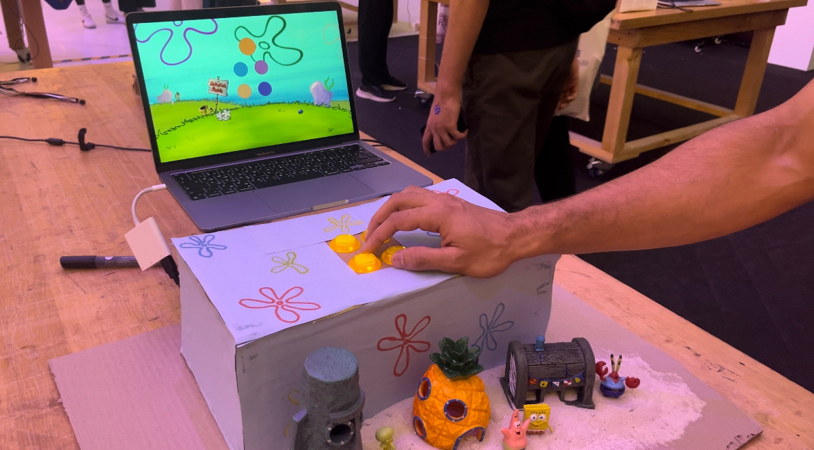
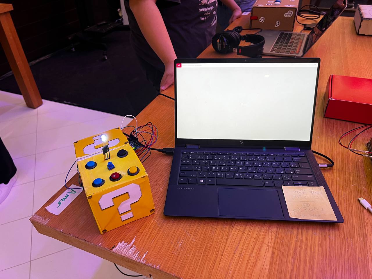
The game has an interactive set up with 4 buttons replacing the keys on the keyboard. By pressing the buttons, the players are interacting with the game on the P5 sketch. This is shown in the following pictures:
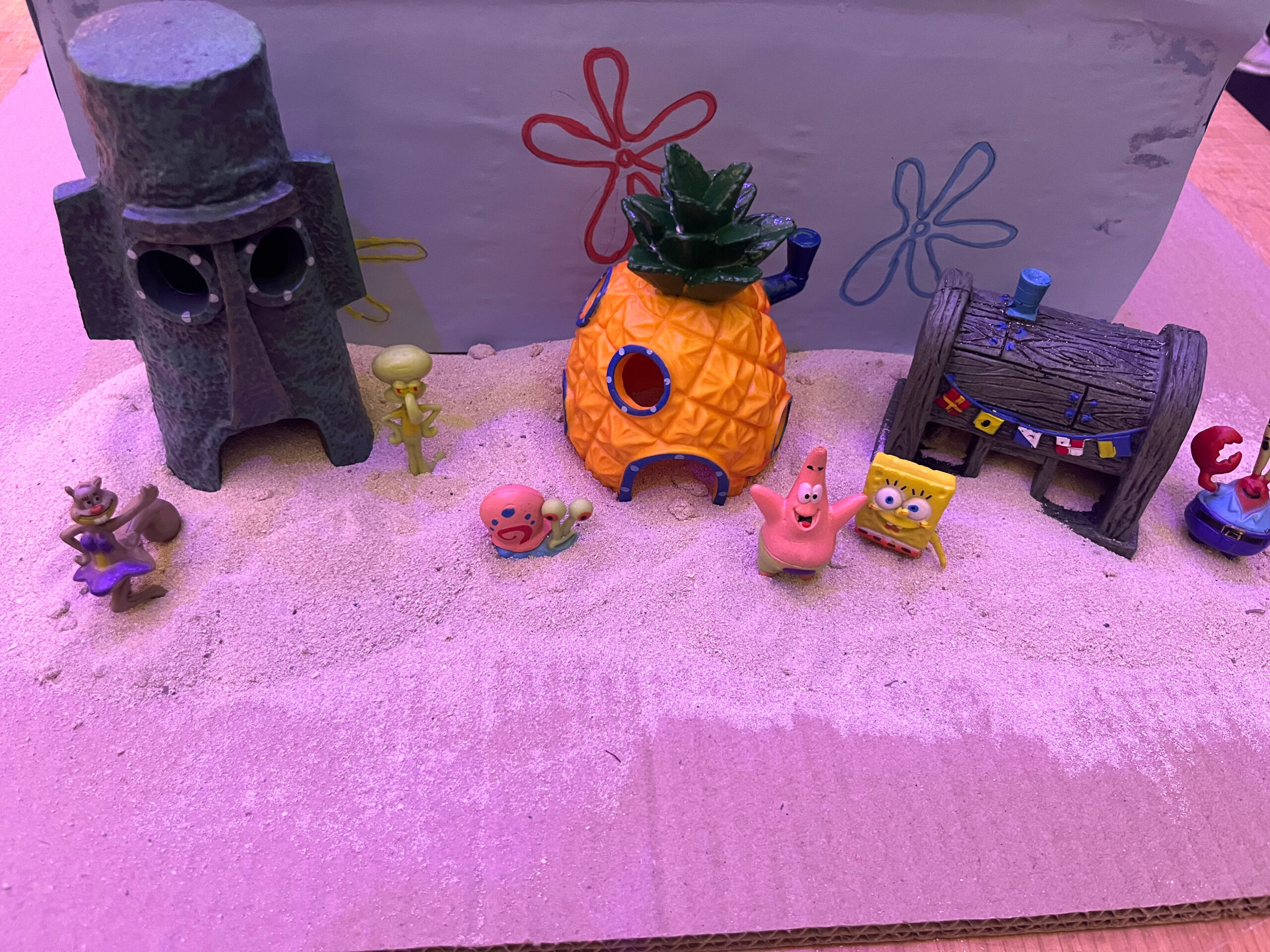
As shown in the picture, the aesthetics of the game are really important especially since this game is also targeting kids. Having a nice set up of “Bikini Bottom” was really important in my opinion to make sure that the game is not just functioning well but also looks appealing to the players.
The use of these buttons makes it so much easier than the keyboard according to the users that tested the game. Moreover, when user testing, most of the students suggested having a less hectic and messy background so that the player can focus and memorize the colors of the circles without getting distracted by the background. There was some debate over whether the users should get to see the score they achieved or not. Since it is a memory game, I thought the players should focus more on memorizing and enhancing their focus span than focus on the score, so I did not make it visible to the players.
// Define pin numbers for buttons
const int leftButtonPin = 2;
const int upButtonPin = 3;
const int downButtonPin = 4;
const int rightButtonPin = 5;

void setup() {
  Serial.begin(9600);
  // Set button pins as inputs
  pinMode(leftButtonPin, INPUT);
  pinMode(upButtonPin, INPUT);
  pinMode(downButtonPin, INPUT);
  pinMode(rightButtonPin, INPUT);
}

void loop() {
  // Read button states and send data over serial
  int leftButton = digitalRead(leftButtonPin);
  int upButton = digitalRead(upButtonPin);
  int downButton = digitalRead(downButtonPin);
  int rightButton = digitalRead(rightButtonPin);

  // Send button states to serial
  Serial.print(leftButton);
  Serial.print(",");
  Serial.print(upButton);
  Serial.print(",");
  Serial.print(downButton);
  Serial.print(",");
  Serial.println(rightButton);

  // Delay to control the rate of data transmission
  delay(100);
}
This Arduino sketch manages four buttons connected to the board, using pins 2, 3, 4, and 5 for left, up, down, and right buttons respectively. The setup() function initializes serial communication at 9600 baud and sets the button pins to input mode. The loop() function continuously reads the state of each button using digitalRead() and sends these states over the serial connection using Serial.print(). Each button state is outputted sequentially and separated by commas, with a newline at the end of each set via Serial.println(). A delay(100) is included to control the rate of data transmission, preventing data overflow and ensuring manageable communication speeds.
function drawGamePage() {
  //song.play();
  background(backgroundImage);
  if (currentPage == 2 || currentPage == 3) {
    let selected = -1;

    // Map arrow keys to grid positions
    if (ArrowUp == 1 && ButtonPressed == 0) {
      selected = 0; // Top-left
      ButtonPressed = 1;
    } else if (ArrowDown == 1 && ButtonPressed == 0) {
      selected = 1;
      ButtonPressed = 1; // Top-right
    } else if (ArrowRight == 1 && ButtonPressed == 0) {
      selected = 2;
      ButtonPressed = 1; // Bottom-left
    } else if (ArrowLeft == 1 && ButtonPressed == 0) {
      selected = 3;
      ButtonPressed = 1; // Bottom-right
    } else if (
      ArrowLeft == 0 &&
      ArrowRight == 0 &&
      ArrowUp == 0 &&
      ArrowDown == 0
    ) {
      ButtonPressed = 0;
    }

    // Check if the selected color matches the currentColor
    if (selected != -1) {
      if (gridColors[selected] == currentColor) {
        prepareNextLevel();
      } else {
        currentPage = -1;
      }
    }
  }

  fill(nextColor);
  ellipse(windowWidth / 2, 200, 120, 120);
  let padding1 = windowWidth / 2 - 75;
  let padding2 = windowHeight / 2 - 100;
  for (let i = 0; i < gridSize; i++) {
    for (let j = 0; j < gridSize; j++) {
      fill(gridColors[i * gridSize + j]);
      ellipse(
        padding1 + j * (ellipseSize + 50),
        padding2 + i * (ellipseSize + 50),
        ellipseSize,
        ellipseSize
      );
    }
  }
}

function drawOverPage() {
  //laugh.play();
  background(gameOverImage);
  textAlign(CENTER, CENTER);
  textSize(32);
  fill(0);
  text("Game Over", width / 2, height / 2 - 100);

  // Draw "Again" button
  fill(200); // Light grey button background
  rect(width / 2 - 100, height / 2, 200, 50);
  fill(0); // Black text
  text("Again", width / 2, height / 2 + 25);

  // Draw "Home" button
  fill(200); // Light grey button background
  rect(width / 2 - 100, height / 2 + 70, 200, 50);
  fill(0); // Black text
  text("Home", width / 2, height / 2 + 95);
}

function drawInstructionPage() {
  //song.play();
  background(instructionsImage);
  fill(0);
  textSize(24);
  textAlign(LEFT, LEFT);
  text("Instructions", width - 810, height - 710);
  textSize(16);
  text("Welcome to the Memory Game! Here's how to play:", width - 840, height - 655);
  text("1. Memorize the colors shown on top of the screen.", width - 840, height - 625);
  text("2. Use the buttons to select the correct color from the grid.", width - 840, height - 595);
  text("3. Match the colors correctly to advance to the next level.", width - 840, height - 565);
  text("Press Space Bar to select Serial Port", width - 840, height - 535);
  textAlign(CENTER, CENTER);
  rect(width - 780, height / 2 - 40, 80, 40);
  fill(200);
  text("Continue", width - 740, height / 2 - 20);
}


function draw() {
  background(220);
  if (!serialActive) {
    text("Press Space Bar to select Serial Port", 20, 30);
  } else {
    text("Connected", 20, 30);
  }

  if (currentPage == 0) {
    drawStartPage();
  } else if (currentPage == 1) {
    drawInstructionPage();
  } else if (currentPage == 2) {
    drawFirstPage();
  } else if (currentPage == 3) {
    drawGamePage();
  } else if (currentPage == -1) {
    drawOverPage();
  }
}
The P5 sketch code is maily about the game page which has the conditions that make the game more interesting. The drawGamePage() function in this p5.js code is designed for a memory game, where it handles the game logic and user interactions during gameplay. It first sets the background and checks if the game is on specific pages (like a game level). The function maps arrow key inputs to grid selections, managing state with a ButtonPressed flag to avoid repeated selections. If a selected color from the grid matches a target color (currentColor), the game progresses to the next level; otherwise, it switches to a game over page. It dynamically renders colored ellipses on a grid, representing game elements. Additionally, other functions like drawOverPage() handle the game over screen, displaying buttons for restarting or returning to the home screen, and drawInstructionPage() displays the game instructions. The main draw() function coordinates these pages based on the current game state, updating the display and handling transitions between different parts of the game, such as starting, instructions, gameplay, and game over scenarios.
Aspects of the project I am proud of:
Game Logic Implementation: The effective mapping of user inputs (arrow keys) to game actions and the incorporation of game state management ensures that the gameplay is both challenging and engaging.
Serial Communication: The use of serial communication to connect Arduino inputs to the p5.js game logic demonstrates a robust application of cross-platform communication techniques, vital for interactive media projects.
Areas for Future Improvement:
Complexity and Features: Introducing additional levels of difficulty, more complex game mechanics, or multiplayer capabilities could increase the game’s replay value and appeal to a broader audience. Also having new shapes, characters to memorize and not just the circles can be fun!
Extensive Testing and Debugging: Conducting more thorough testing across different platforms and setups could identify and resolve any existing bugs or issues with user interactions, ensuring a smooth and reliable user experience.
Throughout the semester, I’ve created projects that, in a sense, gamified concepts in Biology. Back when I worked on my Assignment 2, I had expressed a desire to allow users to select multiple color options for the bacteria. So, this project grew out of that desire, in addition to giving people a chance to practice very basic Synthetic Biology / Microbiology.
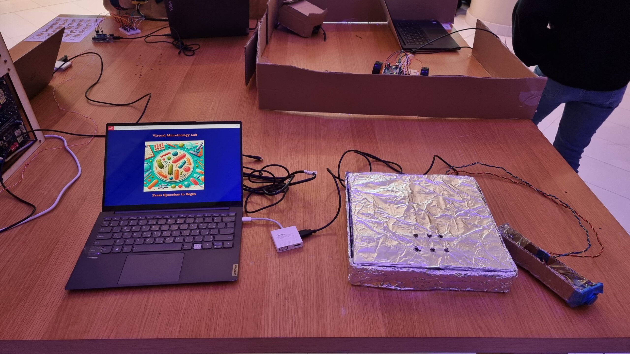
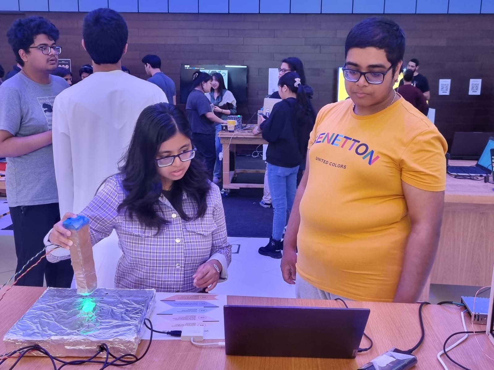
In essence the concept is simple. There are six prepared agar plates. Additionally, there are six fluorescent proteins: Green Fluorescent Protein [green], mCherry [pinkish-red], mOrange [orange], mKO [yellow], mCerulean [cyan], and Blue Fluorescent Protein [BFP]. All of these proteins fluoresce naturally under UV light and are not usually produced by bacteria. Instead, they are obtained from bioluminescent animals and can thus be used as a method to verify whether a certain gene editing technique worked in bacteria. But that biology-heavy introduction aside, the idea was that users select the fluorescent protein-modified bacteria they want and “pipette” them into the corresponding plate. Then, they can incubate the bacteria to watch them grow and toggle the UV light to actually see the fluorescence.
Implementation
Interaction Design
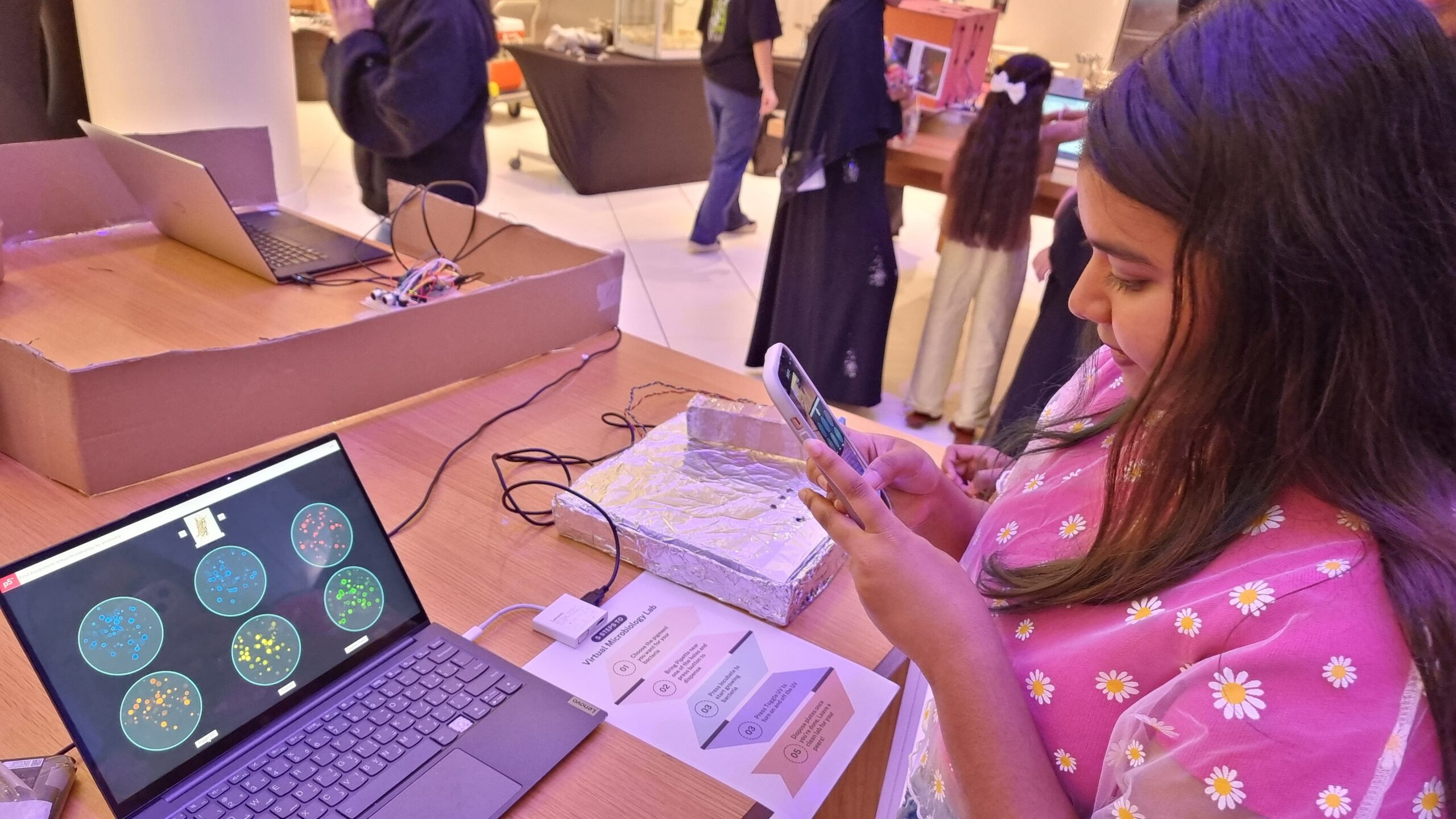
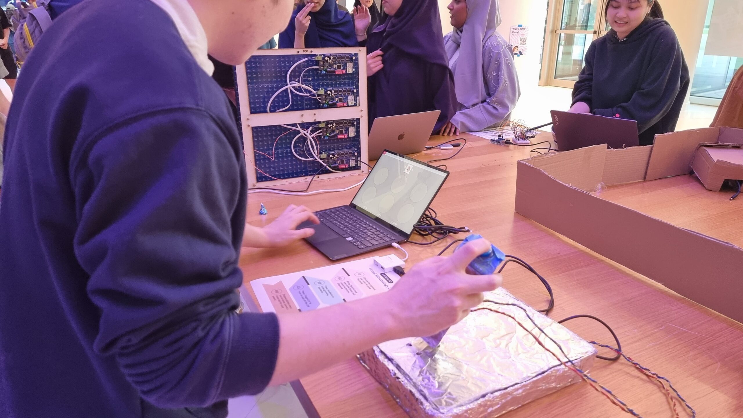
As mentioned above, the interaction design has two main parts: the laptop-focused part, and the physical prototype part. On the laptop, the user can press on-screen buttons to change the fluorescent protein, incubate the bacteria already plated, toggle the UV lamp, and dispose of the plates. On the physical prototype, the user has to bring the pipette to one of six holes (each of which contains a hidden photoresistor) and press a button to “dispense” bacteria. The idea is that the user controls which color of bacteria they want to grow on which plate.
Arduino Code
The Arduino code was relatively simplistic, as its main purpose was to read the values from the hidden photoresistor and send them to p5. The secondary function was to receive color values from p5 and control an RGB LED with it to glow with the corresponding color.
The above code basically detects light intensity crossing a certain threshold value above the background light intensity. The reason why pin 0 had a lower threshold was because the associated photoresistor appeared to be more sensitive to light and reached near maximum intensity even under ambient light conditions. Three separate photoresistors behaved that way, so I decided to just change the code instead. It is likely that all three photoresistors were of the same type (i.e. one that was different from the others).
Below is my (highly confusing) assembly diagram of the project, as created using TinkerCAD.
p5 Code
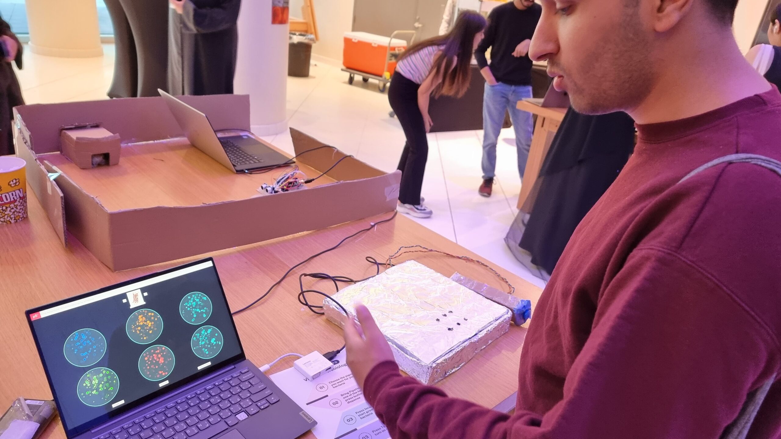
The p5 code was mostly based on my old code from Assignment 2. However, I had to modify it quite a bit to both work with Serial Communication and also restrict the agar growth to specific plates rather than the entire area of the sketch. Like last time, I used randomGaussian() for the growth. I used this instead of Perlin Noise as I rather liked the higher degree of randomness the Gaussian random gave me, as the Perlin Noise did tend towards aggregation rather than spread, as expected.
Also, to avoid colonies from appearing beyond the plate borders, I just used an if() statement to only display those colonies that were generated within borders. While I originally wanted to use a while() loop to truly restrict generation to within the plate, I soon discovered that a while() loop interfered with Serial Communication, thus causing the program to crash. Since a minimum of 5 and a maximum of 30 colonies were generated every frame, or 60 times per second, I felt that the few colonies leaving the plate borders that would not be displayed wouldn’t really be missed.
for (let i = 0; i < numColonies; i++) {
  // Gaussian random to ensure aggregation towards center
  colonyX = randomGaussian(cultures[d].x, spread);
  colonyY = randomGaussian(cultures[d].y, spread);
  colonyR = random(2, 15);
  if (
    dist(
      colonyX,
      colonyY,
      plates[cultures[d].loc].x,
      plates[cultures[d].loc].y
    ) <=
    plates[d].diameter / 2 - colonyR - 3
  ) {
    strokeWeight(3);
    if (uv) {
      stroke(cultures[d].border);
      fill(cultures[d].col);
    } else {
      stroke(colonyBorder);
      fill(colonyColor);
    }
    ellipse(colonyX, colonyY, colonyR);
  }
}
Serial Communication
Serial Communication in this project was two-directional.
From the p5 sketch, the RGB values of the fluorescent protein colors were sent to the Arduino, which would use these as inputs for red, blue, and green light. I converted the hexadecimal color value to decimal using parseInt() which I learned to use from this tutorial.
let colRgb = hexToRgb(colonyUVColors[currentProt]);
let sendToArduino = colRgb[0] + "," + colRgb[1] + "," + colRgb[2] + "\n";
writeSerial(sendToArduino);
From the Arduino component, the information about which photoresistor had crossed the threshold and was thus the plate on which the user had “dispensed the bacteria” was communicated to the p5 sketch. As explained earlier, this information would only be sent when the light intensity crossed a certain value above background light intensity.
There were numerous challenges faced. I enumerate some of them below.
1) To detect? Or not to detect?
As anyone who uses photoresistors (or any kind of variable resistance sensors really) must know, photoresistors have wildly inconsistent results. Not just that, since their resistance changes according to light intensity, any changes in background light intensity would also potentially trigger false positives, or could even mask actual detections leading to false negatives. Both are bad.
There are two ways of combatting this. The first is to create an enclosure that minimizes background light intensity. A “dark room” as such. My original plan included this in some aspect, as I had planned to build a mini version of a laminar flow hood as the housing for the project. However, due to my lack of any abilities in fabrication, this was out of the question.
So, the next solution lies in code. Instead of trying to detect light intensity above a certain threshold, using the difference in intensity between background light intensity and the light to be detected would be a better solution. So, I decided to put statements asking the Arduino to measure light intensity at startup through the setup() function. But this presents another problem, as you might have guessed. How would I account for changing light intensity during runtime? This could be done by using the button output (the one the user was pressing to pipette) as a condition for when the actual light intensity was being sensed, and otherwise continually detecting background light intensity while the user did not press the button. This actually worked surprisingly reliably, even in weird lighting conditions.
2) Watch me crank that (solder) boy
Soldering was a pain. It looks easy from the outside but I was clearly doing something wrong because making 8 solder connections took me 2.5 hours. One mistake that I discovered I was doing is that in order to “beautify” the solder, I was trying to melt it a bit so that it flowed around the wire better and looked smoother, but the whole thing would melt off and drop unceremoniously. I quickly learned not to do that.
3) If it can’t be fixed by tape, you’re not using enough
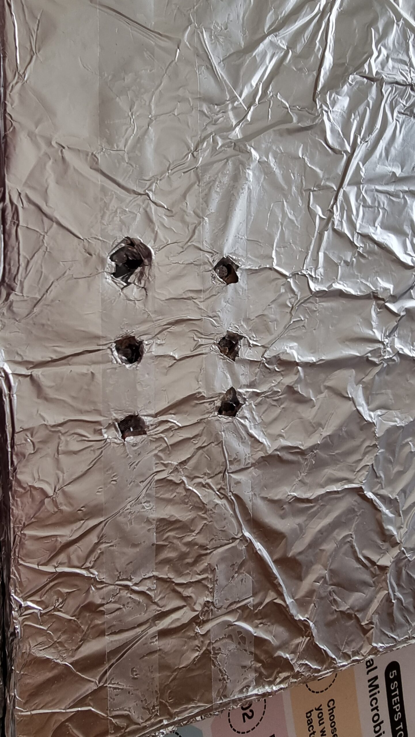
As mentioned in my Resources Used section, much of my project is held together with a ton of Scotch tape. I mean, half of an entire roll of Scotch tape. I initially wanted to join the cardboard segments making up the pipette with hot glue, but I quickly discovered that hot glue guns wouldn’t work too well. Not because of the strength of hot glue (hot glue was strong enough), but because the cardboard itself was too weak to handle shear stress from being pressed on while only being linked using hot glue to one/two joints. Tape allows for more surface area of contact and also holds the pieces together like a rubber band would instead of just creating a joint. Also, a bunch of tape was used to hold the aluminium taut against the pizza box both to prevent crinkles and also to avoid the foil itself from shifting around and covering the potentiometer windows.
4) Serial communication: More drama than Hindi TV serials
Serial Communication. It’s a useful tool to create projects linking digital artwork on p5 to physical processes through an Arduino.
But it requires so much bug-fixing to get right.
Right off the bat, as described earlier, a while() loop to keep regenerating random positions that were only within disc borders, while working perfectly fine in a p5-only situation, would crash as soon as it came to Serial Communication, most likely because the while() loop interfered with the Serial receiving/sending of data. This required me to switch to an if() statement to only display those colonies that generated within the plate borders, using the dist() function to calculate distance between centers of colonies and plates.
Also, I noticed that occasionally, Serial communication would stop entirely between the p5 and Arduino components. This, I found, was because my code initially sent a number associated with each light sensor when the corresponding light sensor detected the LED. What happens if it doesn’t detect the LED? You’re right, the Arduino stops sending data, breaking the Serial Communication. This, I fixed by asking the Arduino to send an arbitrarily picked ‘6’ whenever no sensor detected the LED.
The final challenge in fact couldn’t be solved by me. I noticed both during User Testing and the show itself that if the user switched colors too quickly (as excited users wanting to try out the different colors are wont to do) Serial lagged on the Arduino side and the LED would display a color associated with a different protein. The time taken to recover gradually increased with runtime, eventually reaching a longest period of 1 minute of recovery time. I found that p5 was indeed sending the correct information with virtually no delay, but without the ability to get Serial callouts from the Arduino while Serial Communication was running meant that I could not identify what was causing the lag in the Arduino.
User Testing
Reflections
Overall, I’m rather proud of my project. It allowed me to convey my love for Biology and allowed people, irrespective of their background, to try their hand at a simple experiment, without requiring any prior lab prep work or worry of contamination and other challenges when it comes to growing bacteria. Also, the simulation was a lot faster than actual bacteria growth (taking E. coli for example, at full growth, each second is equivalent to about 6 hours). Seeing the excited faces at the IM showcase as the fluorescence under UV was revealed to them was (as cheesy as it sounds) worth all the time I spent on this project. That I would say is the aspect I am most proud of. But other than that, I am particularly proud of my way of detecting the LED light using a difference in light intensity method than a raw threshold, as it eliminated the biggest possible source of variation.
However, there is definitely room for improvement. Most of what I include below comes from feedback actually given to me during the IM showcase, or from behaviors that I observed.
The project was essentially not very intuitive. While I did have a poster with written instructions, like all other written forms of instruction, it was ignored, thus leaving most users confused about what to do without my assistance. The instructions being unclear also didn’t help.
The interaction could flow better. I could map the change in fluorescent proteins to the keyboard instead of mouse clicks as (a) a lot of MacBook users kept accidentally right-clicking on my Windows laptop due to the differences in what is sensed by each device’s trackpad; and (b) most people stuck to the same color for all six plates as they forgot or did not bother with changing the color.
As some of my Biology major friends pointed out, it would be cool if I had six tubes with six LEDs of different colors representing each of the fluorescent proteins. And then, instead of selecting the protein from the screen, I could potentially ask the user to “pipette” from one of the tubes and into each well, just like in a real Biology lab. However, this would require both an RGB sensor, as well as a way to distinguish between pipetting in and out. One button with two different depths (like in real pipettes) wouldn’t work, and two separate would be too cumbersome to hold and press. But, it would definitely increase the immersion if possible.
Resources Used
Most of the electronics were from the base Sparkfun Arduino Uno Rev3 SMD kit. I had to borrow additional photoresistors and an arcade button from the IM lab consumables for the photoresistors. Additionally, I borrowed solid core wires and solder to extend my connections and electrical tape to insulate them.
For the physical prototype itself, the pipette was made of cardboard from the IM lab held together with a LOT of tape a hole was punched into one side of the pipette for the wires, and at the bottom for the LED. A larger hole was made at the top for the arcade button.
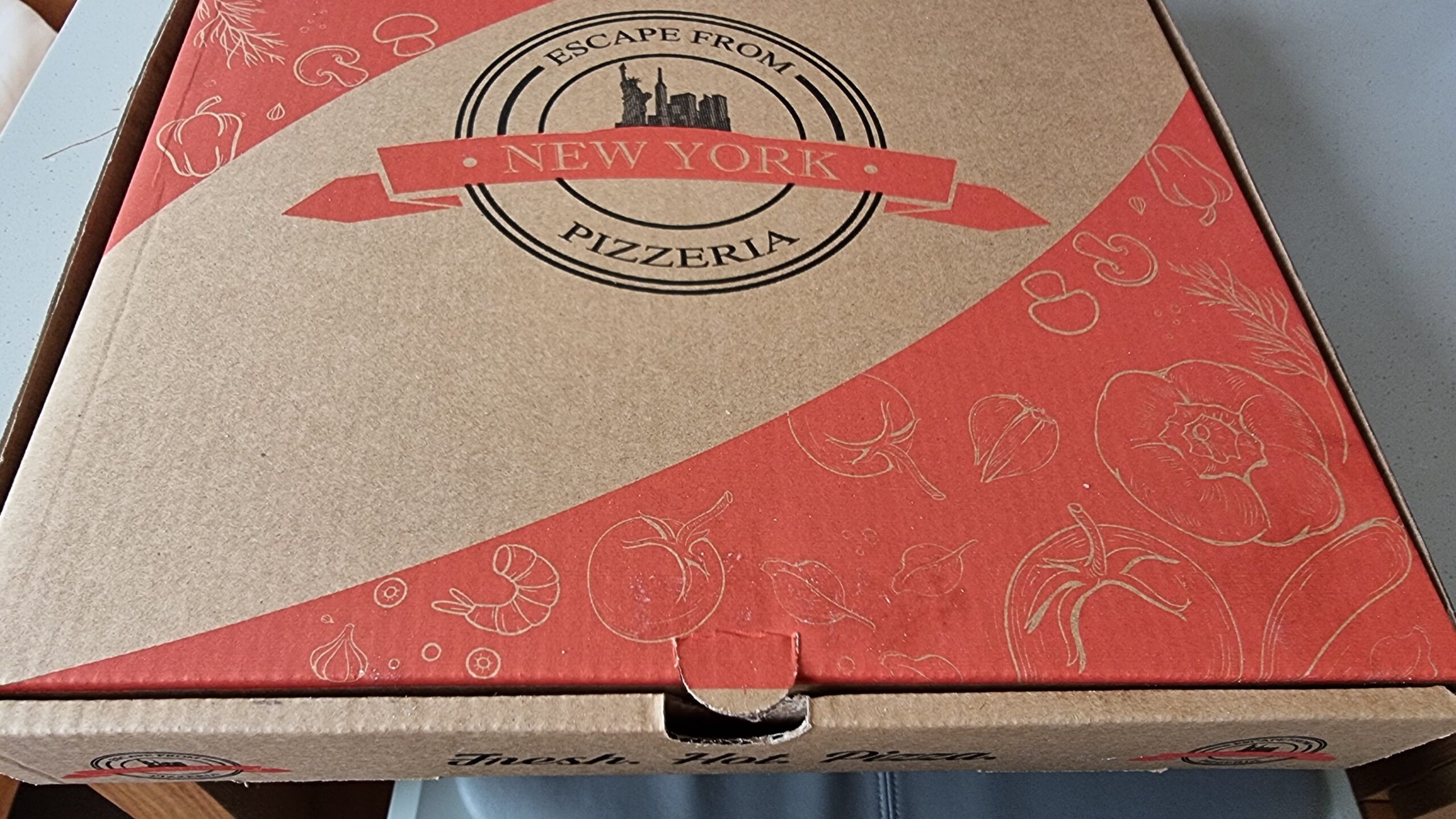
The main working surface was based on a pizza box that was covered in foil and punched with six holes to serve as windows for the photoresistors. All of my circuitry went into the pizza box, which would make it convenient to make any quick fixes. I could just open the box and work on it rather than have to cut anything out of a more permanent casing.
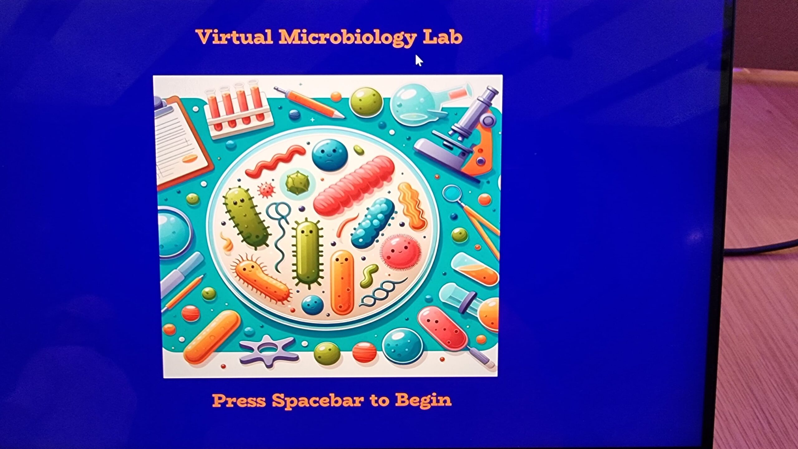
Software side, the cover image was generated using DALLE3, while the images of the fluorescent proteins were obtained from the Protein Data Bank (PDB) maintained by the Research Collaboratory for Structural Bioinformatics (RCSB).
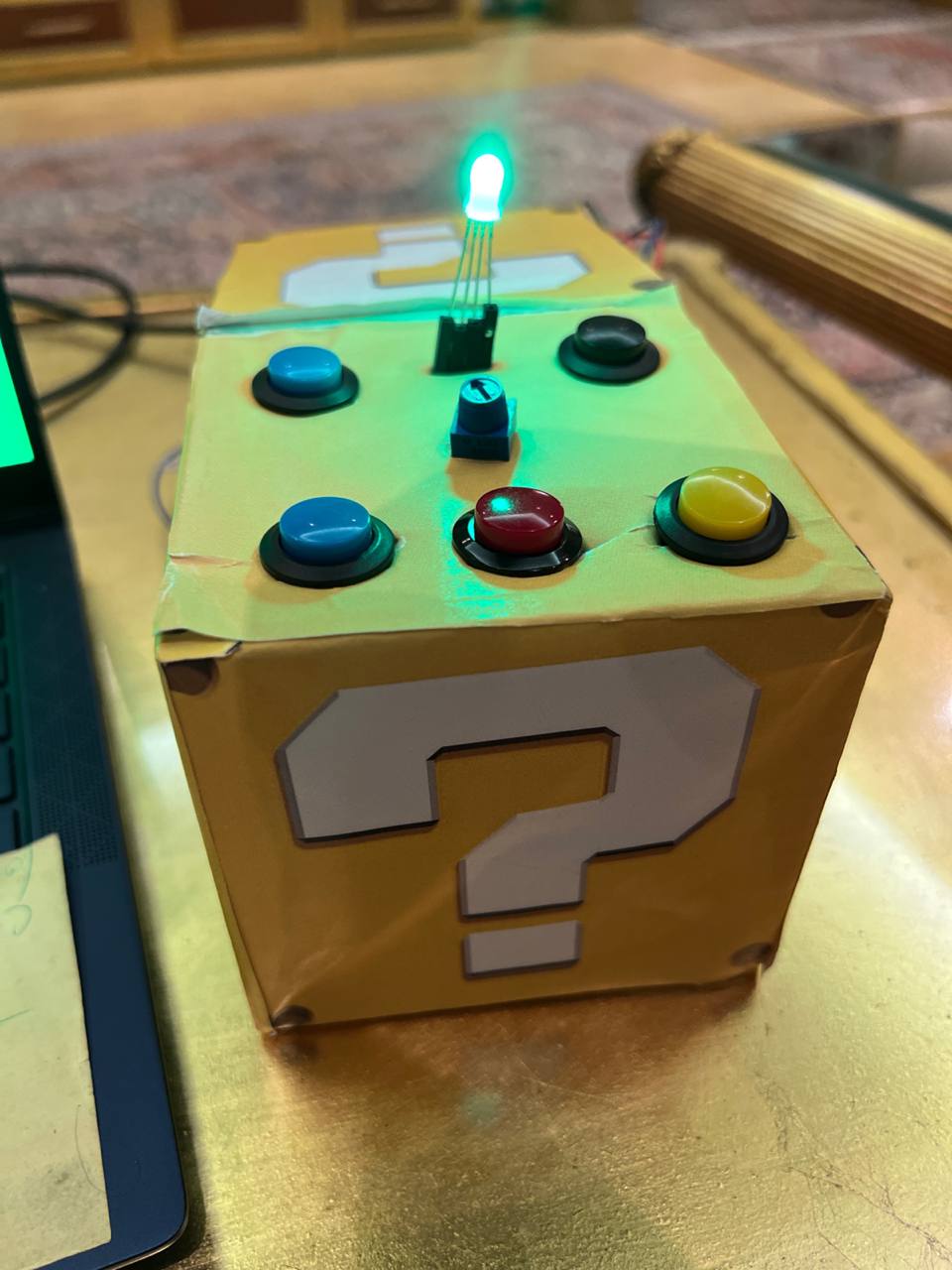
For my final project, I made an interactive mood lamp with five push-buttons corresponding to five moods: Day, Calm, Study, Energetic, and Night. Each mood lights up with a matching color on the arduino and p5, as well as background music from p5.
Implementation
I used a total of 5 push-buttons (obtained from the IM Lab), each for one of the moods. I also used a potentiometer to control the light brightness, an RGB LED for the light itself, and some 220ohm resistors I had at home (because I lost the ones from the kit), as well as the breadboard and jumper wires.
Each button is connected to one of the arduino’s digital ports; I used the internal pullup resistors for them to reduce the amount of components needed and to make the circuit simpler. The RGB LED is connected through resistors to PWM ports to have control over the brightness. The potentiometer is connected to an analog input.
When the arduino starts, the light is set to orange as a starting color, with a matching screen on p5 prompting the user to select a mood. Whenever any of the five buttons are pressed, the light switches to that mood’s color, as well as the p5 screen, and matching music is played. Light brightness can be controlled continuously through the potentiometer.
Arduino Code
// Pin definitions for buttons
const int greenButtonPin = 2;
const int redButtonPin = 4;
const int blueButtonPin = 7;
const int whiteButtonPin = 5;
const int blackButtonPin = 6;

// Pin definitions for RGB LED
const int redLEDPin = 9;
const int greenLEDPin = 10;
const int blueLEDPin = 11;

// Pin definition for the potentiometer
const int potPin = A0;

// Variable to store the last pressed button
int lastPressedButton = 0;

// Current color variables (Default set to orange)
int currentRed = 255;
int currentGreen = 50;
int currentBlue = 0;

void setup() {
  Serial.begin(9600);

  // Initialize button pins
  pinMode(greenButtonPin, INPUT_PULLUP);
  pinMode(redButtonPin, INPUT_PULLUP);
  pinMode(blueButtonPin, INPUT_PULLUP);
  pinMode(whiteButtonPin, INPUT_PULLUP);
  pinMode(blackButtonPin, INPUT_PULLUP);

  // Initialize RGB LED pins
  pinMode(redLEDPin, OUTPUT);
  pinMode(greenLEDPin, OUTPUT);
  pinMode(blueLEDPin, OUTPUT);

  // Set initial LED color and brightness to maximum
  updateBrightness(255); // Ensure full brightness on startup
  setColor(currentRed, currentGreen, currentBlue); // Start with default mood 'Start' (Orange)
  Serial.println("Start");
}

void loop() {
  // Continuously adjust the brightness based on potentiometer reading
  int brightness = analogRead(potPin) / 4; // Scale to 0-255
  updateBrightness(brightness);

  // Check each button and change the LED color and print the mood if changed
  checkButton(greenButtonPin, "Study", 0, 255, 0);
  checkButton(redButtonPin, "Energetic", 255, 0, 0);
  checkButton(blueButtonPin, "Calm", 0, 0, 255);
  checkButton(whiteButtonPin, "Day", 255, 255, 255);
  checkButton(blackButtonPin, "Night", 128, 0, 128);
}

void setColor(int red, int green, int blue) {
  // Store the current color settings
  currentRed = red;
  currentGreen = green;
  currentBlue = blue;
}

void updateBrightness(int brightness) {
  // Adjust the PWM output to LED pins based on the current color and new brightness
  analogWrite(redLEDPin, map(currentRed, 0, 255, 0, brightness));
  analogWrite(greenLEDPin, map(currentGreen, 0, 255, 0, brightness));
  analogWrite(blueLEDPin, map(currentBlue, 0, 255, 0, brightness));
}

void checkButton(int buttonPin, String mood, int red, int green, int blue) {
  if (digitalRead(buttonPin) == LOW && lastPressedButton != buttonPin) {
    delay(50); // Debounce delay
    if (digitalRead(buttonPin) == LOW) { // Confirm the button is still pressed
      lastPressedButton = buttonPin;
      setColor(red, green, blue);
      updateBrightness(analogRead(potPin) / 4); // Update brightness immediately with new color
      Serial.println(mood);
    }
  }
}
Basically, whenever a button corresponding to a mood other than the current one is clicked, the LED color is updated to the color corresponding to the new mood and the mood name is sent to P5 over serial communication. Additionally, the LED brightness is being continuously updated based on changes to the reading from the potentiometer.
P5 Code
let bgColor = [255, 165, 0]; // Orange Starting Color
let moodText = "Mood Lamp"; // Default text to display
let mood = "Start"

// Music Variables
let dayMusic;
let calmMusic;
let studyMusic;
let energeticMusic;
let nightMusic;

// Load all audio
function preload() {
  dayMusic = loadSound('Wii Sports - Title (HQ).mp3');
  calmMusic = loadSound('Animal Crossing New Leaf Music - Main Theme.mp3');
  studyMusic = loadSound('Gusty Garden Galaxy Theme - Super Mario Galaxy.mp3');
  energeticMusic = loadSound('Title Screen - Mario Kart Wii.mp3');
  nightMusic = loadSound('Luma - Super Mario Galaxy.mp3');
}

// Setup canvas
function setup() {
  createCanvas(windowWidth, windowHeight);
  textSize(32);
  textAlign(CENTER, CENTER);
}

function draw() {
  background(bgColor);
  fill(255);
  text(moodText, width / 2, height / 2);

  if (!serialActive) {
    text("Click the screen to select Serial Port", width / 2, height / 2+50)
  }
  else if (mood == "Start") {
    bgColor = [255, 165, 0];
    moodText = "Select one of the mood buttons to being...";
    dayMusic.stop();
    calmMusic.stop();
    studyMusic.stop();
    energeticMusic.stop();
    nightMusic.stop();
  }

  if (mood == "Day") {
    bgColor = [200, 200, 200];
    moodText = mood;
    calmMusic.stop();
    studyMusic.stop();
    energeticMusic.stop();
    nightMusic.stop();
    if (!dayMusic.isPlaying()) dayMusic.loop();
  }

  if (mood == "Calm") {
    bgColor = [0, 0, 255];
    moodText = mood;
    dayMusic.stop();
    studyMusic.stop();
    energeticMusic.stop();
    nightMusic.stop();
    if (!calmMusic.isPlaying()) calmMusic.loop();
  }

  if (mood == "Study") {
    bgColor = [0, 255, 0];
    moodText = mood;
    calmMusic.stop();
    dayMusic.stop();
    energeticMusic.stop();
    nightMusic.stop();
    if (!studyMusic.isPlaying()) studyMusic.loop();
  }

  if (mood == "Energetic") {
    bgColor = [255, 0, 0];
    moodText = mood;
    calmMusic.stop();
    dayMusic.stop();
    studyMusic.stop();
    nightMusic.stop();
    if (!energeticMusic.isPlaying()) energeticMusic.loop();
  }

  if (mood == "Night") {
    bgColor = [128, 0, 128];
    moodText = mood;
    calmMusic.stop();
    dayMusic.stop();
    studyMusic.stop();
    energeticMusic.stop();
    if (!nightMusic.isPlaying()) nightMusic.loop();
  }

}

// Serial code copied from example sketch, with some modifications

function mousePressed() {
  if (!serialActive) {
    // important to have in order to start the serial connection!!
    setUpSerial();
  } else mood = "Start";
}

function readSerial(data) {
  if (data != null) {
    // make sure there is actually a message
    // split the message
    mood = trim(data);
  }
}

function windowResized() {
  resizeCanvas(windowWidth, windowHeight);
}
Basically, after serial connection is established by the user, the canvas is updated to reflect the current mood whenever a new mood is read from the arduino on the serial connection, and the corresponding audio plays as well.
P5 Embedded
User Testing
I had each of my sisters my project to try (prior to making a case and finalizing it).
My first sister managed to figure it out without any instructions from me, surprisingly even knew which COM port to select. She did not figure out that brightness can be controlled by the potentiometer though.
My other (younger) sister managed the same, but did not know which what to do when the COM port prompt came up. She also did not realize that brightness can be controlled.
I had built the casing using cardboard I got from Rahaf from Student Affairs. The material is very flimsy and I should replace it with something more permanent and stable. I had to solder wires to the red button immediately before the showcase because it didn’t have any; I also used two blue buttons because I couldn’t find a white one.
Additionally, I could aim to make the project more fun and interactive, but overall it’s a nice idea that people seemed to enjoy at the showcase.
For this assignment, we were tasked to control an ellipse using sensor data from arduino.
For this, I’m using readings from a potentiometer.
Arduino Code
void setup() {
  Serial.begin(9600);
}

void loop() {
  int sensorValue = analogRead(A0); // Read the value from the potentiometer
  Serial.println(sensorValue); // Give P5 the value over serial
  delay(10);
}
P5 Code
let sensor = 0;

function setup() {
  createCanvas(400, 400);
}

function draw() {
  background(220);
  if (!serialActive) text("Click the screen to connect serial.", 50, 50); // display text to connect serial

  let x = map(sensor, 0, 1023, 0, 400); // map sensor to canvas
  ellipse(x, 200, 50, 50); // Draw the ellipse in the middle of the screen
}

// Serial code copied from example sketch, with some modifications

function mousePressed() {
  if (!serialActive) {
    // important to have in order to start the serial connection!!
    setUpSerial();
  }
}

function readSerial(data) {
  if (data != null) {
    // make sure there is actually a message
    // split the message
    sensor = trim(data);
  }
}
The reading dives into the fascinating history of how design intersects with disability, and of how focusing on design for disability doesn’t just solve immediate problems but can also inspire broader changes in the design world.
What’s really interesting about this is the idea that solving specific problems for disabled users can actually lead to major innovations that benefit everyone. It’s a powerful reminder that good design is about more than just looks or functionality; it’s about thoughtful innovation that considers all users. This perspective encourages us to think differently about design and its potential impact, pushing for high standards and creativity in all areas, including those designed for disability.
This reading challenges the current trend in technology interfaces, which he criticizes as merely “Pictures Under Glass.” He argues that this approach severely underutilizes the complex capabilities of human hands, which are not only meant for touching but also for manipulating objects in rich and varied ways. This is intriguing because it prompts us to rethink how we interact with technology. Victor’s perspective is a wake-up call to consider more innovative and natural interactions beyond the confines of screens and opens up exciting possibilities for future technological developments that genuinely enhance human abilities rather than constrain them.
What I find particularly interesting is the emphasis on the need for inspired people to drive this change. It’s a reminder of the power of visionairy thinking in technology and the responsibility of creators and funders to strive for meaningful advancements, not just incremental changes, not just accepting technology as it is, but imagining and working towards what it could be to enhance human interaction.
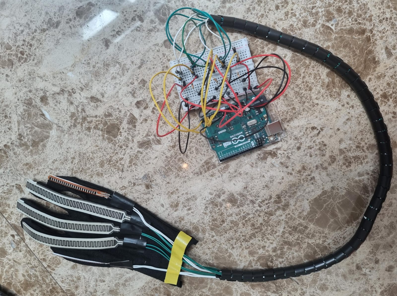
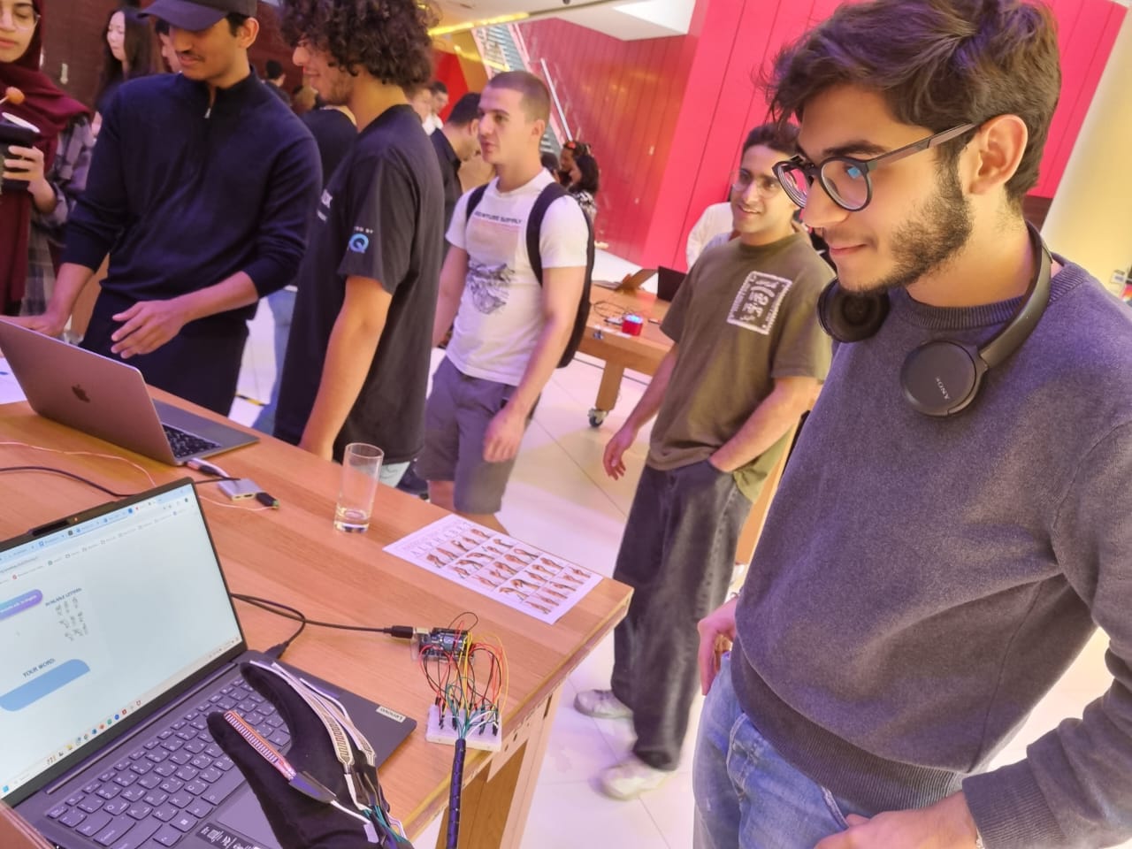
My final project is a Sign Language glove that translates American Sign Language (ASL) to English and vice versa. The aim is to facilitate communication and improve accessibility for individuals who are deaf or hard of hearing. This is an idea I have had for years but I finally have the technical skills to implement it. My motivation arises from my aim to break down the boundaries that hinder people with disabilities in society. Unfortunately, sign language is not a common skill for hearing people. On the other hand, while some people with hearing impairment know lipreading, for most of them, Sign Language is their first language.
This interactive system enables individuals that use sign language to have two-way communication with non-sign language users effectively. The user wearing the glove can fingerspell words using the American Sign Language alphabet. The program then vocalizes the word to assist Sign Language users with speech. On the other hand, a hearing person can type their word into the program which will display the signs for each letter so the Sign Language user can interpret it.
The glove incorporates flex sensors on each finger which detects how much the finger is bent. Arduino processes this data and sends the finger configurations to the p5.js sketch.
//fingers
int flexPin1 = A1;
int flexPin2 = A2;
int flexPin3 = A3;
int flexPin4 = A4;
int flexPin5 = A5;

void setup() {
  // Start serial communication so we can send data
  // over the USB connection to our p5js sketch
  Serial.begin(9600);
}

void loop() {
  // Read flex sensor values
  int pinky = analogRead(flexPin1);
  int ring = analogRead(flexPin2);
  int middle = analogRead(flexPin3);
  int index = analogRead(flexPin4);
  int thumb = analogRead(flexPin5);

  // Send flex sensor values to p5.js
  Serial.print(pinky);
  Serial.print(",");
  Serial.print(ring);
  Serial.print(",");
  Serial.print(middle);
  Serial.print(",");
  Serial.print(index);
  Serial.print(",");
  Serial.print(thumb);
  Serial.println();

  delay(100);
}
The p5.js sketch interprets the gestures to recognize the corresponding letters of the alphabet. This is done using the signRecognition function below which checks whether each flex sensor value is in the appropriate range.
It is limited to only 9 letters for now. I did implement a few more letters but later removed it to avoid clashes between the letter ranges. The reason for this is a lot of ASL signs have very similar finger configurations and I would require additional or more accurate sensors to implement all 26 letters.
There will be two options the user can select from: translating ASL to English and translating English to ASL. For the first program, the user spells out a word using the sign for each letter and pressing right arrow to confirm the letter and move to next position. You can edit the word if you made a mistake by using backspace, and to add a space you input no letter. This is done using the keyPressed() function.
function keyPressed() {
  if (key == " ") {
    setUpSerial();
  }

  if (keyCode === ENTER) {
    if (page === 1) {
      page = 2;
    } else if (page === 2) {
      page = 3;
    } else if (page === 4) {
      finalizeWord();
      // page = 3; // Go back to options page
    }
  } else if (keyCode === BACKSPACE && page === 4) {
      Word = Word.substring(0, Word.length - 1);
  } else if (keyCode === RIGHT_ARROW && page === 4) {
      Word += letter;
  } else if (keyCode === LEFT_ARROW && (page === 4 || page === 5)) {
      page = 3; // Go back to options page
      Word = '';
  }

  if (keyCode >= 65 && keyCode <= 90) { // Check if the pressed key is a letter
    enteredWord += key.toLowerCase(); // Add the lowercase letter to the entered word
  } else if (keyCode === BACKSPACE) { // Handle backspace key
    enteredWord = enteredWord.slice(0, -1); // Remove the last character from the entered word
  }
}
The p5.js screen reads the word aloud using text-to-speech, using the SpeechSynthesis interface which is a part of the Web Speech API.
For the second program, users will have the option to input a word via keyboard to display the corresponding ASL sign for each letter on the screen below the word.
function translateEnglishPage() {
  image(eng, 0, 0, width, height);
  text(enteredWord, width/2 - 120, height/2+5);

  // Check each letter of the entered word and display the corresponding sign
  let startX = width/2 - 130;
  let startY = height/2 - 70;
  let letterSpacing = 35; // Spacing between images
  for (let imgIndex = 0; imgIndex < enteredWord.length; imgIndex++) {
    let currentLetter = enteredWord.charAt(imgIndex).toLowerCase();
    //calculate position of image based on letter
    let imageX = startX + imgIndex * letterSpacing;
    let imageY = startY+120;

    // Display the image corresponding to the current letter
    if (currentLetter === 'a') {
        image(sign_a, imageX, imageY, 35, 50); }

    // and so on for each letter ...
}
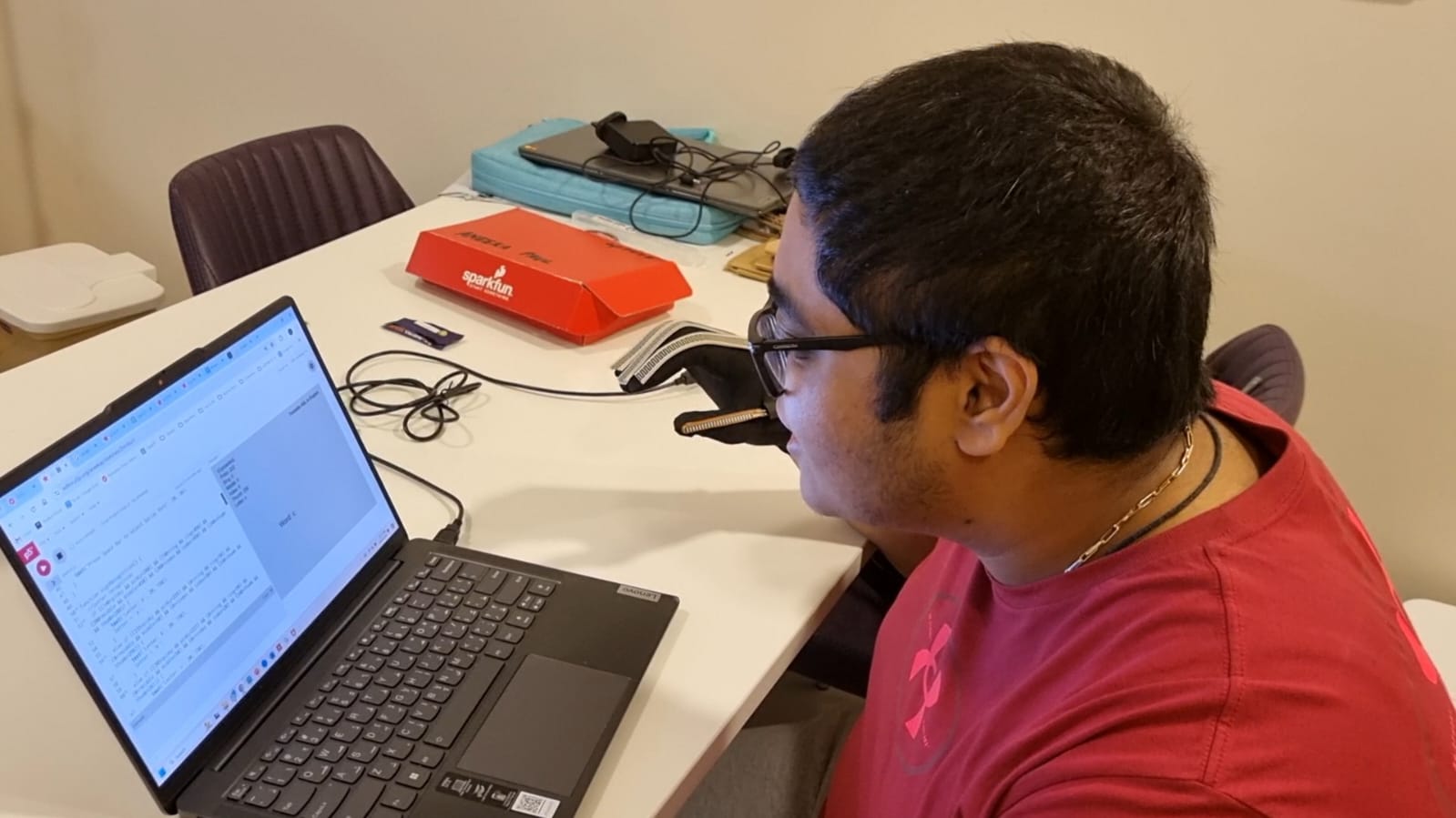
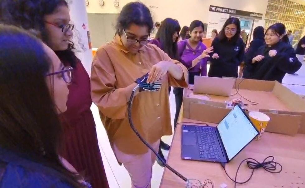
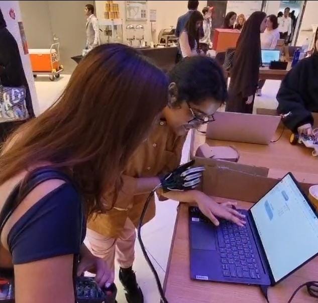
USER TESTING
User testing was helpful but also a bit worrying. The gesture configurations were calibrated to my hand and fingers. I later noticed that it wasn’t working exactly the same with other people’s hands. I thus had to make the ranges less strict to incorporate other hand shapes. However, editing these ranges caused more issues such as introducing clashes between the letters.
challenges and improvements:
The main challenge was calculating the gesture configurations one by one. The flex sensors are pretty sensitive and tend to randomly give different values. I am using two types of flex sensors: 3 thin film pressure sensors and 2 short flex sensors, so I had to calibrate them differently as well. On top of that, one of my flex sensors stopped working midway so my project came to a stop. Thankfully, Professor came to the rescue and bought a new flex sensor for me promptly. Soldering and arranging the wires were also a hassle but I finally got them to look neat.
I am proud of coming up with the idea in the first place. I wanted to create something that was unique and something I am passionate about. I am also proud of sticking to it despite the challenges and making it as accurate as possible.
There is a lot to improve and I started this as a prototype for a long-term project. One major issue is that since some of the finger configurations are so similar, it mixes up between the letters. I also couldn’t implement the entire alphabet. I could add an accelerometer to detect movements as well. I could alternatively try using ML5 for more accurate configurations. I hope to get it to work for entire words as well. I aim to one day create a fully functional portable Sign Language glove.
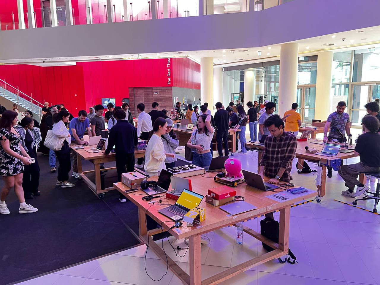
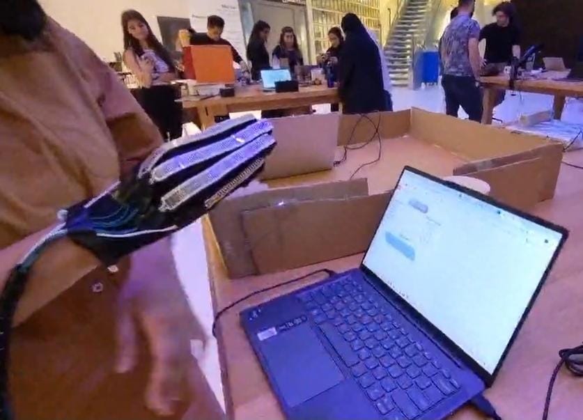
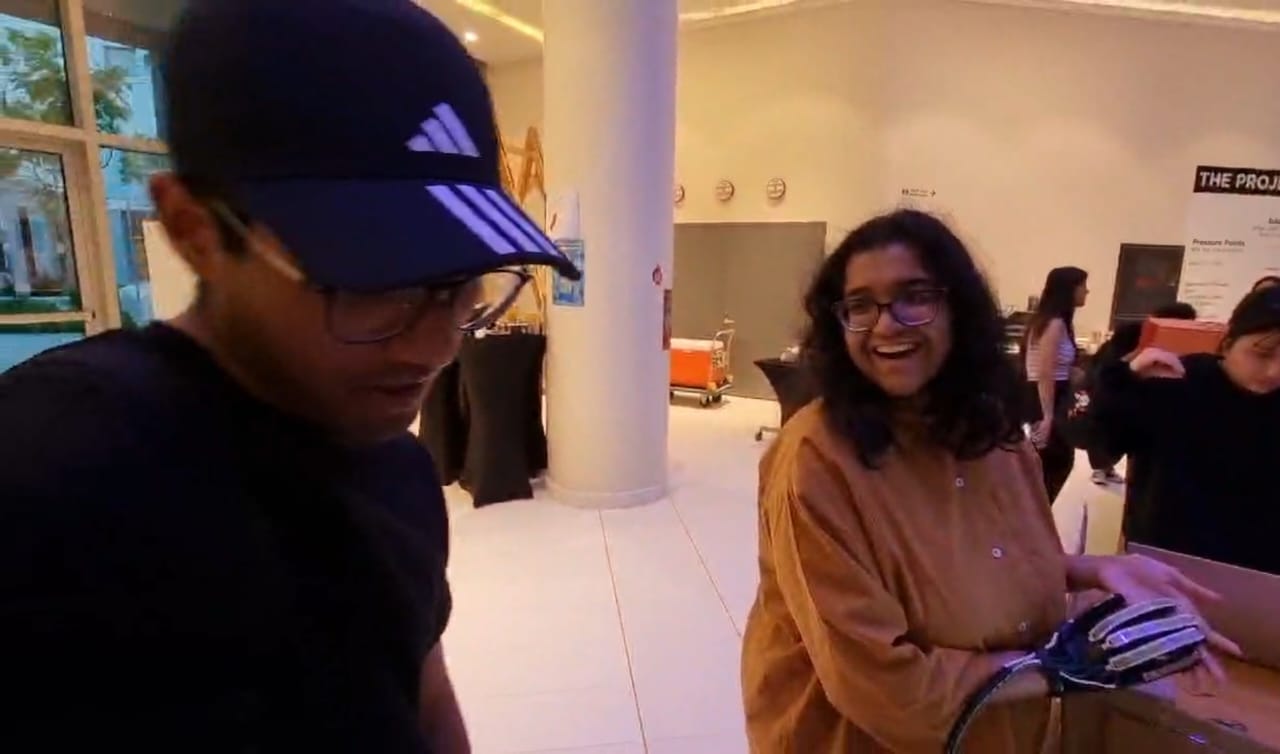
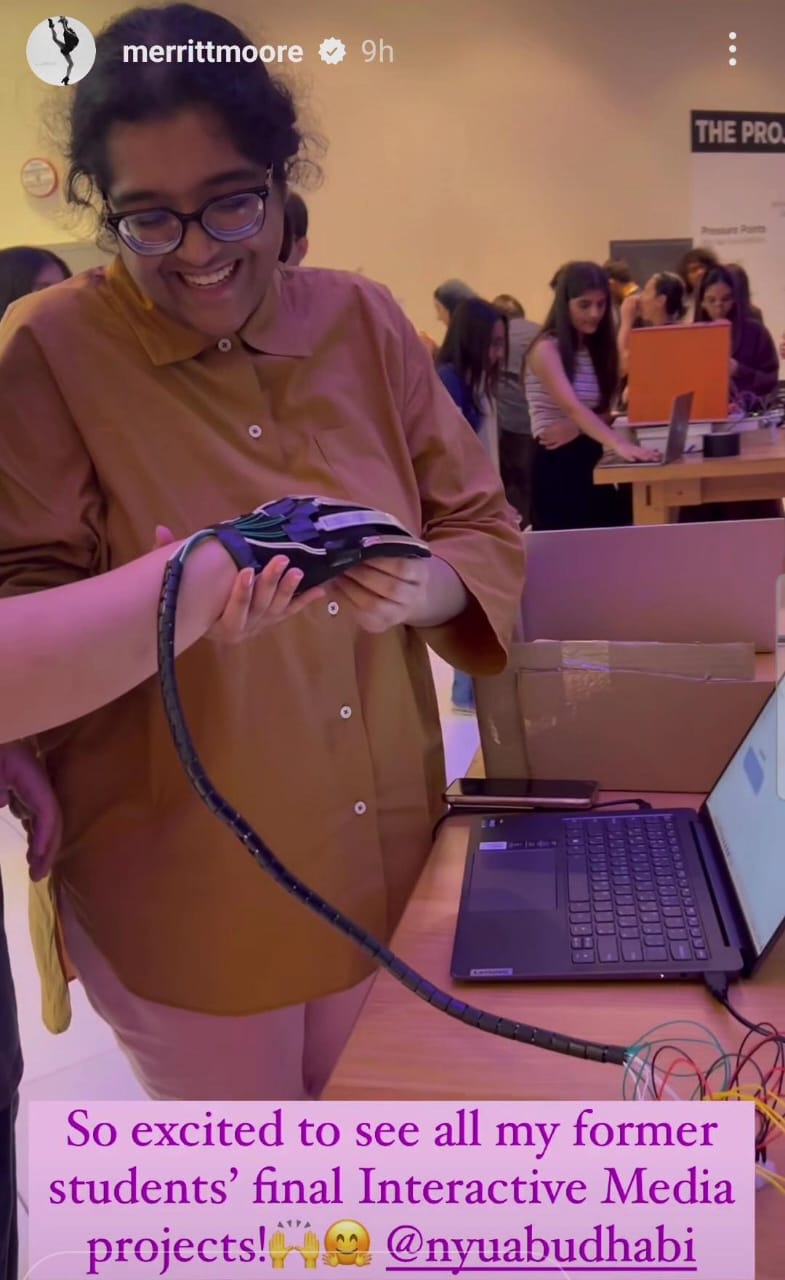
IM Showcase
I made a few changes before I presented my project at the showcase: I recalibrated the ranges for the letters to make it work smoother, I removed a few letters according to Professor’s advice to reduce clashes between letters, and I improved the UI.
During the IM show, when a few people tried on my glove, the tape and wires started coming off, and I had to run back to the IM lab to fix it. Moreover, most of the letters were not working for them since it was still only optimal for my hand. This was because the bending of the flex sensors vary a lot between different hand shapes and sizes. I unfortunately had to resort to only providing them a demonstration after that point and instead gave them the challenge to provide me a word using those letters.
Nevertheless, I had a fun time at the showcase presenting my project and engaging with other people’s projects. I also thoroughly enjoyed taking this course overall and using my creativity and technical skills to come up with projects every week.
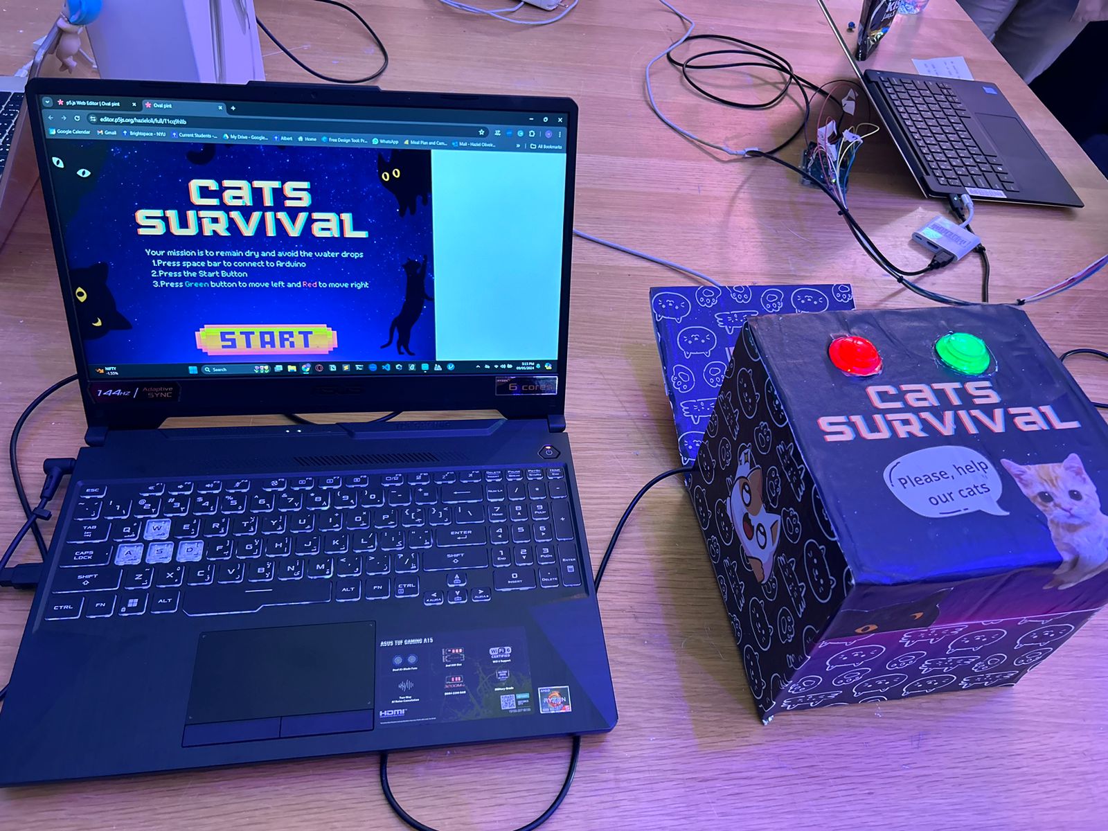
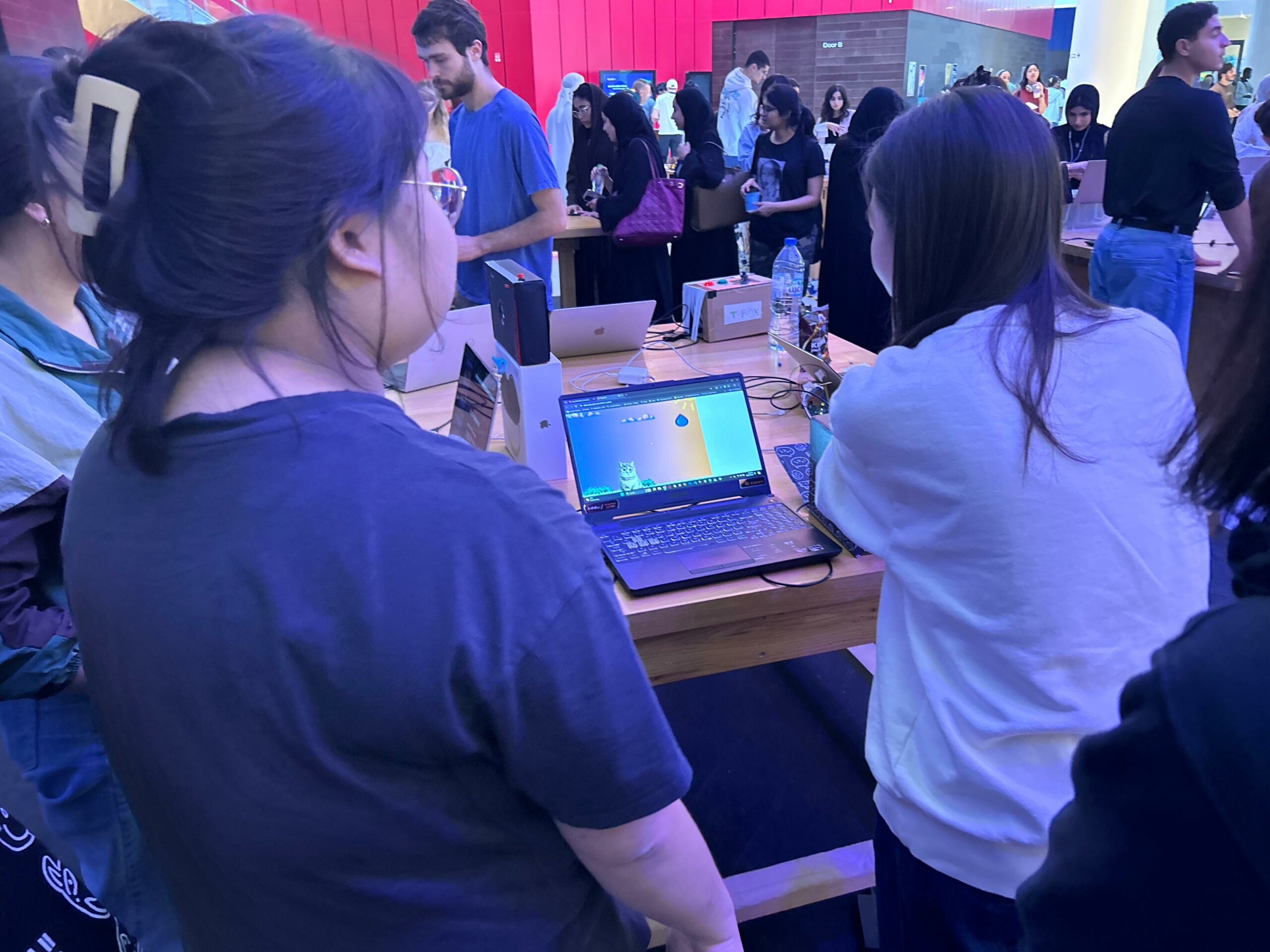
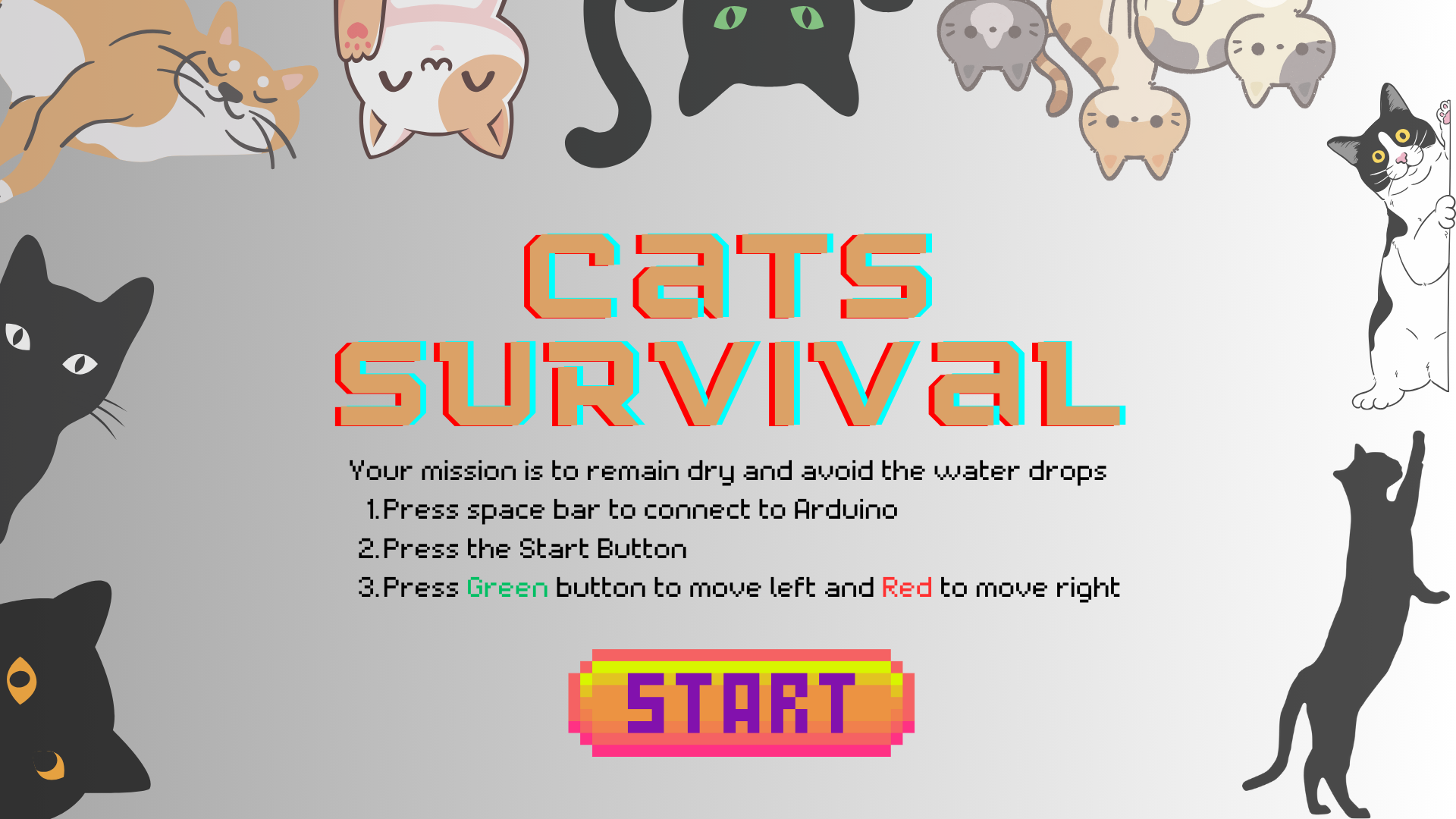
My inspiration for this project was one questions I have asked myself really often during the rainy days: “Where do the campus cats go?” and “How do they survive the rain?”. Based on this, I created “CATS SURVIVAL”, inspired also by the classic arcade games where players navigate through obstacles to achieve a high score. In this game, players engage with Arduino push buttons to control the cat attempting to avoid falling water drops while traversing a colorful campus setting.
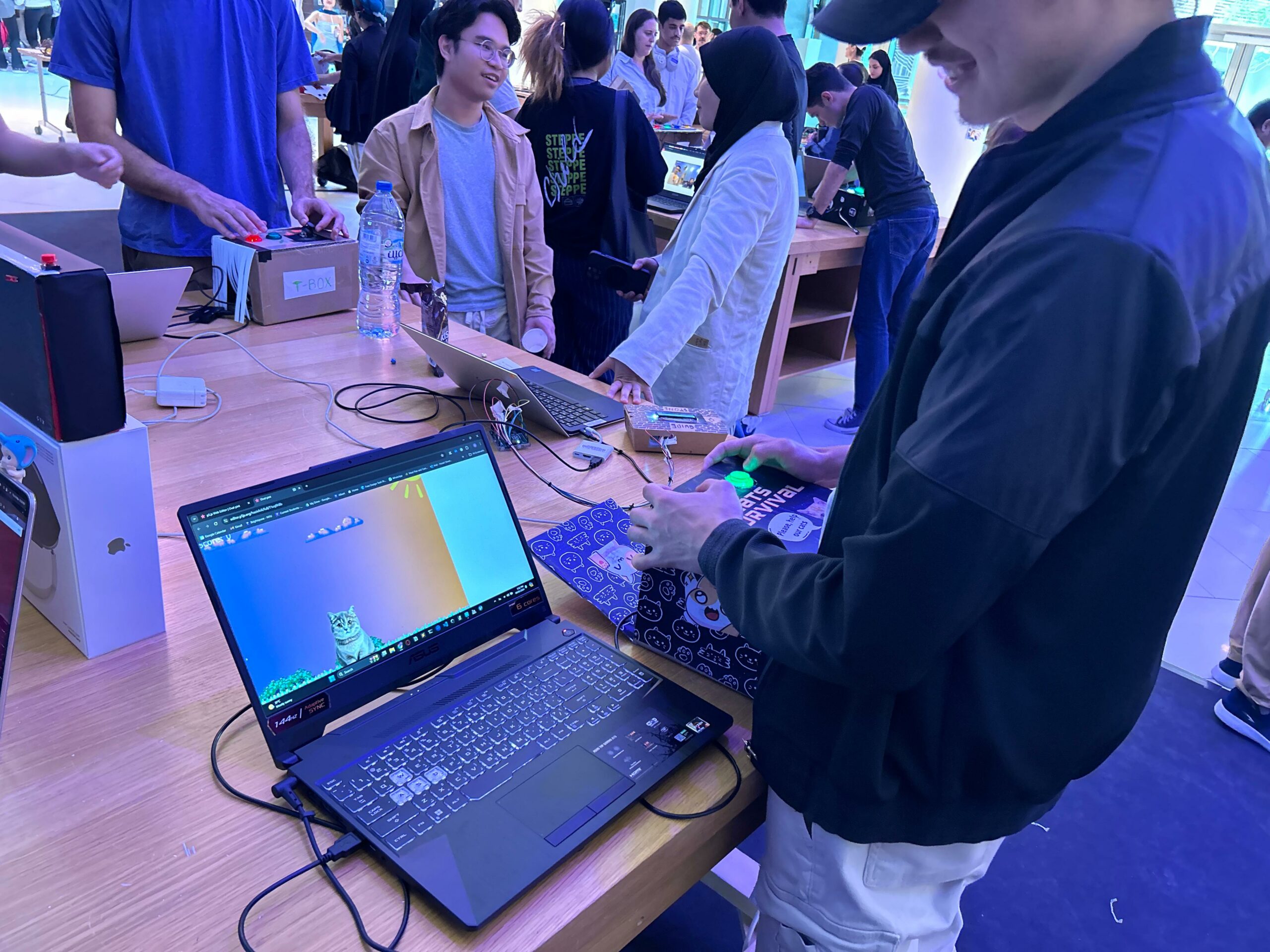
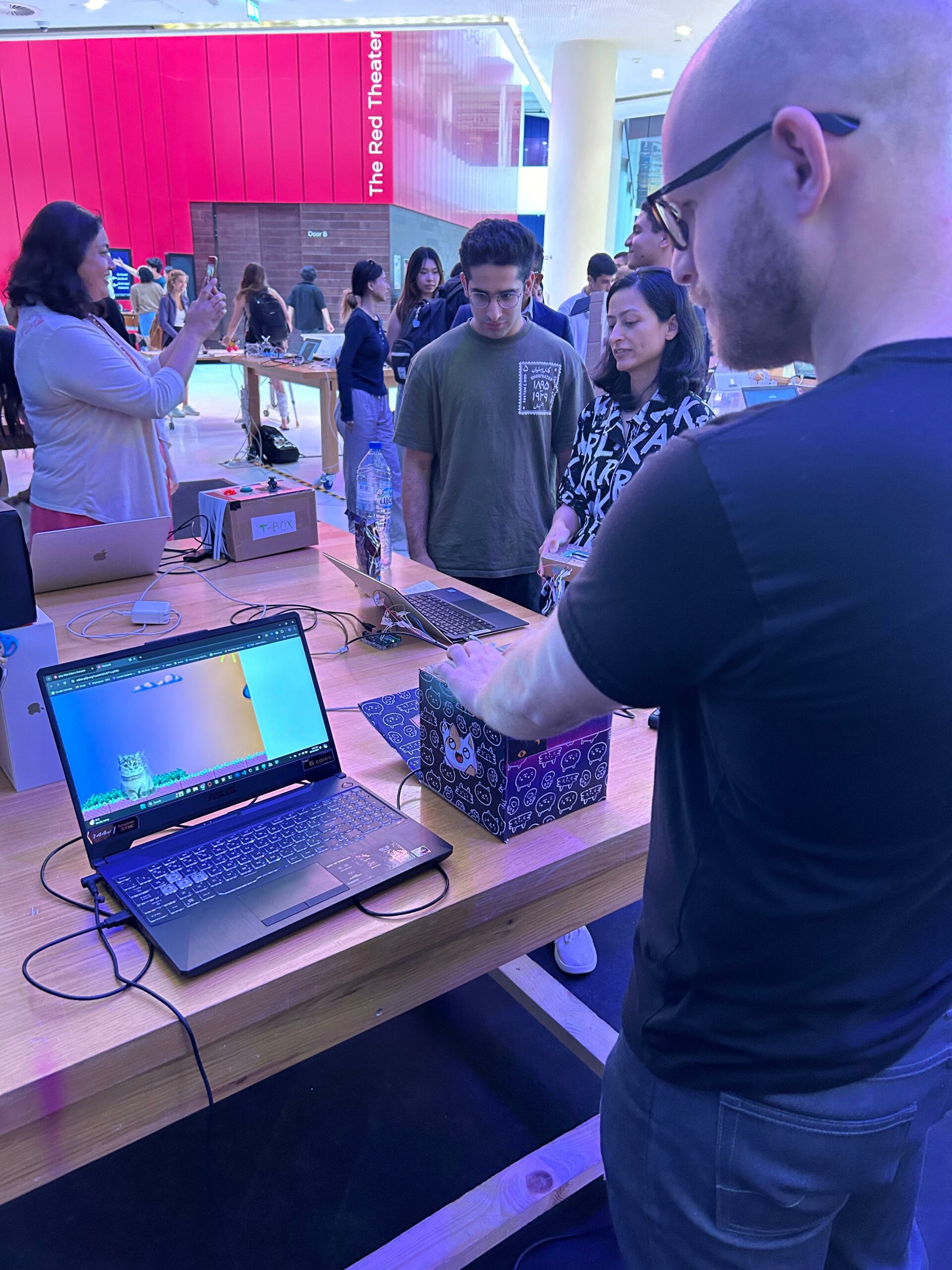
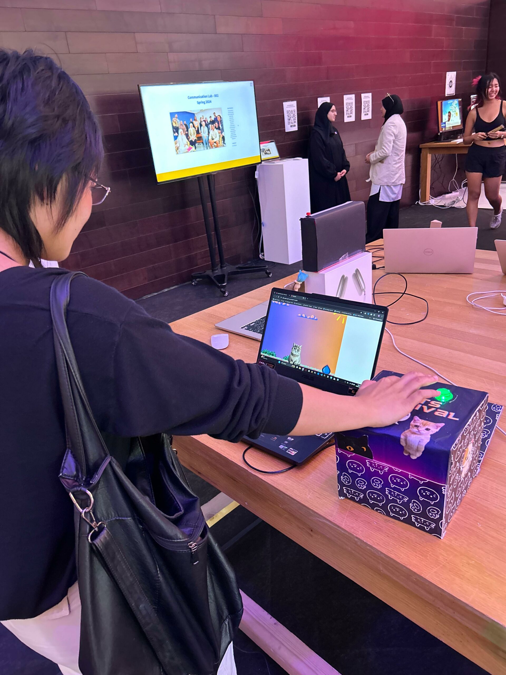
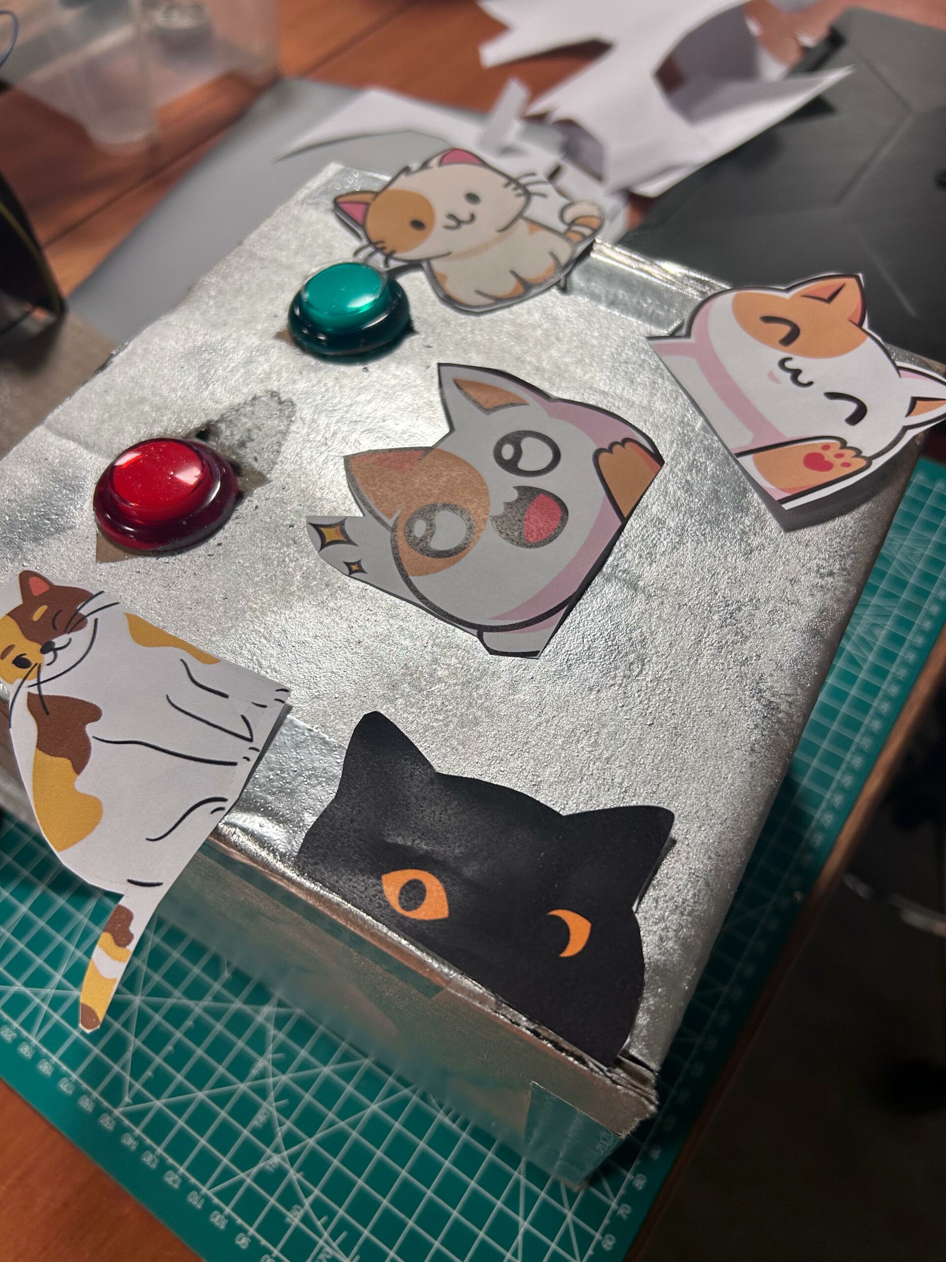
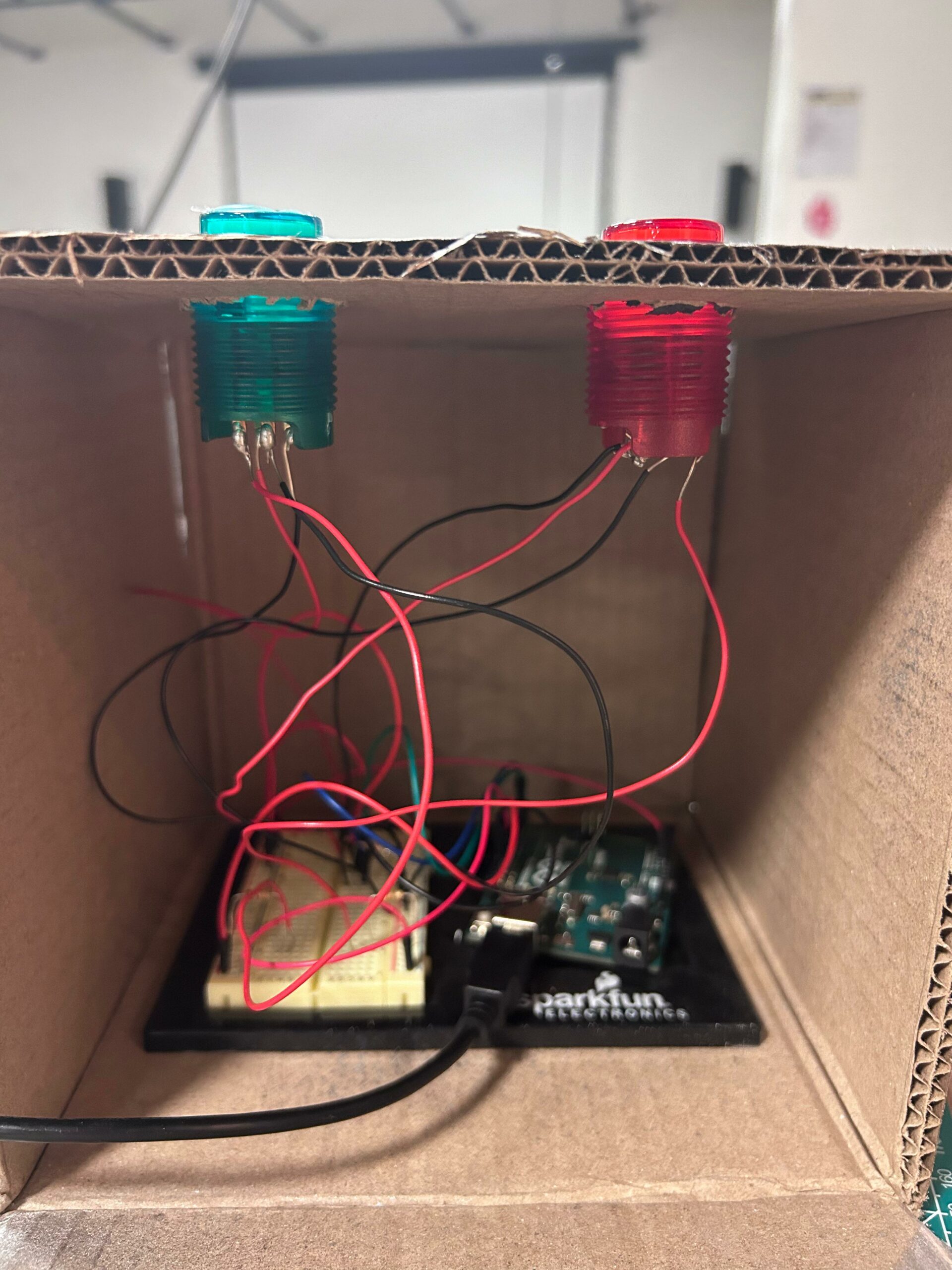
Final Setup:
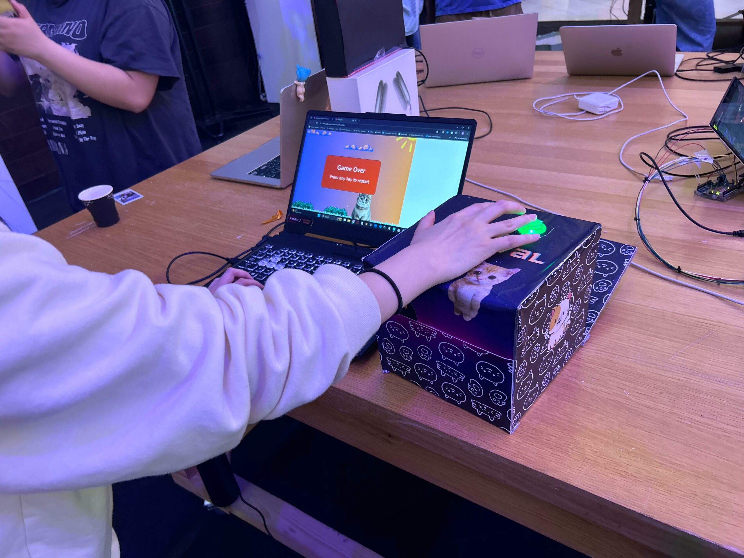
IM Showcase:
How it works:
Players start by launching the game, where they are greeted with a vibrant start page featuring the game’s logo. Once the game begins, the cat automatically appears at the center of the screen, and the player’s objective is to keep the cat from being hit by falling water drops.
Using a connected serial input device (Arduino), players can move the cat left or right, dodging incoming obstacles. Each successful dodge increases the player’s score, while collision with a water drop ends the game.
As the game progresses, the speed, and frequency of falling water drops increase, challenging the player’s reflexes and agility. Upon game over, players can restart the game by pressing any key, offering them the opportunity to beat their previous high score and continue the thrilling dodge-and-survive gameplay.
// Constants won't change. They're used here to set pin numbers:
const int buttonPin1 = 2;  // The number of the first pushbutton pin
const int buttonPin2 = 3;  // The number of the second pushbutton pin
const int ledPin1 = 13;    // The number of the first LED pin
const int ledPin2 = 12;    // The number of the second LED pin

// Variables will change:
int buttonState1 = 0;  // Variable for reading the first pushbutton status
int buttonState2 = 0;  // Variable for reading the second pushbutton status

void setup() {
  // Initialize the LED pins as outputs:
  pinMode(ledPin1, OUTPUT);
  pinMode(ledPin2, OUTPUT);

  // Initialize the pushbutton pins as inputs:
  pinMode(buttonPin1, INPUT_PULLUP); // Changed to INPUT_PULLUP
  pinMode(buttonPin2, INPUT_PULLUP); // Changed to INPUT_PULLUP

  // Start serial communication:
  Serial.begin(9600);
}

void loop() {
  // Read the state of the first pushbutton value:
  buttonState1 = digitalRead(buttonPin1);

  // Check if the first pushbutton is pressed. If it is, the buttonState is LOW:
  if (buttonState1 == LOW) {
    // Turn the first LED on:
    digitalWrite(ledPin1, HIGH);
  } else {
    // Turn the first LED off:
    digitalWrite(ledPin1, LOW);
  }

  // Read the state of the second pushbutton value:
  buttonState2 = digitalRead(buttonPin2);

  // Check if the second pushbutton is pressed. If it is, the buttonState is LOW:
  if (buttonState2 == LOW) {
    // Turn the second LED on:
    digitalWrite(ledPin2, HIGH);
  } else {
    // Turn the second LED off:
    digitalWrite(ledPin2, LOW);
  }

  // Send button states to the p5 sketch
  Serial.print(buttonState1);
  Serial.print(",");
  Serial.println(buttonState2);
  delay(100); // Adjust delay as needed
}
p5 snippet code:
Reading serial data
This function reads data from the serial port, interprets it as button states, and updates the cat’s position accordingly. It ensures that the cat remains within the canvas bounds while moving left or right based on the received data.
This snippet demonstrate how the game can interact with an Arduino board via serial communication to control the cat’s movement.
function readSerial(data) {
  if (data != null) {
    let buttonStates = split(trim(data), ',');
    let buttonState1 = int(buttonStates[0]);
    let buttonState2 = int(buttonStates[1]);

    // Update cat position based on button states
    if (buttonState1 == 1) {
      catX -= 22; // Move left
    }
    if (buttonState2 == 1) {
      catX += 22; // Move right
    }

    // Ensure cat stays within canvas bounds
    catX = constrain(catX, 0, width - catImg.width);
  }
}
Challenges:
The challenge of this game is designing the obstacle mechanics to appropriately balance the game’s difficulty. Since the game operates in full-screen mode, ensuring that the falling obstacles provide a challenging, yet enjoyable experience for players can be tricky. Balancing factors such as the speed, frequency, and size of the obstacles requires careful consideration to prevent the game from becoming too easy or too difficult. Additionally, transitioning from the initial idea of using a potentiometer for input to utilizing two push buttons might pose challenges in terms of code adaptation and player control dynamics.
Future improvements:
Enhance the complexity of the game mechanics and integrating additional features into the circuit in order to elevate the player experience. Adding new gameplay elements such as power-ups, varying obstacle patterns can provide players with more engaging challenges and keep them invested in the game for longer durations.
Incorporating a speaker into the Arduino circuit to synchronize with button presses could add a wider dimension to the gameplay, enhancing immersion and feedback for players. By integrating sound effects or background music that reacts to player actions, such as cat movements and obstacle collisions, the overall gaming experience can be enriched, making it more dynamic and enjoyable.
My concept and inspiration for the final project came from a wish to make something related to cameras/photo-taking/film. Initially, I wanted to make a “camera on wheels”, but then I realized the camera lens would be on my laptop and therefore couldn’t add wheels to it, haha. So, I changed my idea but stuck with the camera concept.
I really enjoy taking photo booth pictures. In fact, I will always push my friends to take them with me if I see a photo booth anywhere. I have collected these grid images from all around the world – Beirut, Abu Dhabi, Paris, New York, Madrid, London, Dubai… And I still have them all saved. They are, to me, a beautiful way of keeping memories in a non-digital fashion, which we tend to towards these days with our phones. I also enjoy the photo booth app on the phone, but the grid layout that results is not the same as a typical, “retro” photo booth.
So, I decided to create a photo booth, which generates four images as a vertical grid!
How to use it
This project is composed of two parts: my laptop with a p5 sketch, and a “camera” I built out of cardboard, inside which there is the Arduino and breadboard. The p5 sketch begins with a start page, that states “photo booth”. There are also instructions: the first step is to click on the screen (when the images are downloaded, the user needs to press on the screen to return to the chrome page); the second step is to press record on the camera to start taking the images.
Once the record button on the camera is pressed, a message is sent from Arduino to p5 to start the photo booth session. Simultaneously, a LED turns on for 20 seconds (which is the length of each session). The four images are taken at five second intervals, with a countdown starting at three seconds. After the twenty seconds have passed, the images are downloaded as a grid, and the user can airdrop it to their phone. Moreover, when the images are done, the start page is displayed again.
Codes
To achieve this, I created a short code on Arduino and a longer one on p5.
Arduino code & circuit
const int BUTTON_PIN = 2;
const int LED_PIN = 13;

bool ledState = false;
int lastButtonState = LOW;
unsigned long startTime = 0; // variable to store the time the button was pressed
const unsigned long interval = 20000; // interval of 20 seconds to indicate when the LED must turn off

void setup() {
  pinMode(BUTTON_PIN, INPUT);
  pinMode(LED_PIN, OUTPUT);
  Serial.begin(9600);
}

void loop() {
  int reading = digitalRead(BUTTON_PIN);

  // checking if the button was pressed
  if (reading != lastButtonState) {
    lastButtonState = reading;
    if (reading == HIGH) {

      ledState = true; // turn LED on
      digitalWrite(LED_PIN, HIGH);
      Serial.println("START"); // send "START" to p5
      startTime = millis(); // start recording the time of button press
    }
  }

  // checking if 20 seconds have passed since the button was pressed
  if (ledState && (millis() - startTime >= interval)) {
    ledState = false; // turn LED off
    digitalWrite(LED_PIN, LOW);
    Serial.println("STOP"); // when 20 seconds have passed, send "STOP" to p5
  }
}
p5 code snippets
→ a function to start the countdown between each image.
function startCountdown() {
  countdownValue = 4; // start the countdown with "nothing"
  clearInterval(countdownTimer); // clear the existing timer, necessary after the first image is taken after the sketch is played
  countdownTimer = setInterval(() => {
    countdownValue--;
    if (countdownValue === 0) {
      // when count is down to 0
      clearInterval(countdownTimer); // stopping the timer
      captureImage(); // capturing an image after the countdown
      countdownValue = 4; // resetting the countdown value back to 4
      setTimeout(startCountdown, interval); // 1-second delay before restarting the countdown
    }
  }, interval); // repeat the function at 1-second intervals
}
→ a function to capture and save the images, with a sound that plays when each image is taken.
function captureImage() {
  if (recording) {
    sound1.play(); // playing the sound when an image is captured

    images[captureIndex] = videos[captureIndex].get(); // capturing the image from each of the four video feeds
    captureIndex++;

    // when the four images are taken, recording is stopped and images are saved as a grid
    if (captureIndex >= 4) {
      stopRecording();
      saveImages();
    }
  }
}
→ determining the countdown value which is then displayed (3, 2, 1 only).
→ function to start recording, which is later activated when the button of the camera is pressed, in a “START” state.
function startRecording() {
  if (!recording) {
    recording = true;
    captureIndex = 0;
    images = [null, null, null, null]; // reset the images array to clear previous session
    clearInterval(countdownTimer); // clear the timer from the previous session

    // clearing the video feeds
    for (let i = 0; i < 4; i++) {
      videos[i].hide(); // hide the video to clear the old feed
      videos[i] = createCapture(VIDEO); // create a new video capture
      videos[i].size(width / 3, height / 3); // set size for each video feed
      videos[i].hide(); // hide the video feed
    }

    startCountdown(); // start the countdown before the first image is captured
  }
}
→ function to stop recording, which is activated by the “STOP” message received by Arduino after the twenty seconds have passed.
// function to stop recording
function stopRecording() {
  print("Recording ended");
  if (recording) {
    recording = false;
    clearInterval(countdownTimer); // clear the countdown timer completely
  }
}
→ function to read the serial data from Arduino.
// read serial data from arduino
function readSerial(data) {
  if (data != null) {
    if (data == "START") { // when data from arduino is "START"
      displayStartPage = false; // switch to the photo booth page
      startRecording(); // start recording
    } else if (data == "STOP") { // when data from arduino is "STOP"
      displayStartPage = true; // display start page
      stopRecording(); // stop recording
    }
  }
}
Sketch
And here is a link to the full screen sketch:
https://editor.p5js.org/alexnajm/full/LVOvvvioq
What I am proud of
I am particularly proud of finally being able to understand how serial communication works. For me, I had a hard time processing it in practice, although in theory it did make sense. Applying it for this project which I made from scratch, as compared to the exercises we did in class, enabled me to better grasp the concept of serial communication.
Additionally, I am proud of how this project has evolved. I had a few ideas in between which truly were not challenging enough. I am not saying that this project is super complex, but it definitely took time and effort to try and understand how everything works in order to achieve this final result.
Challenges
I encountered multiple challenges, first, creating serial communication from scratch. Again, it was a bit hard for me to apply the concepts.
Another challenge was getting the feeds and countdown to reset after each session. At first, the images from the previous session remained on the feeds, which means the user couldn’t see a live version but only the images taken. Gladly, I was able to figure it out – same for the countdown.
Areas for future improvement
Eventually, I would like to create a better design for the p5 sketch. As of now, I feel like it’s a bit… bland.
I would also like to try to incorporate filters, which the user can choose from before taking the images. This was a bit hard as the images cannot be downloaded with the filter, and I did not want the grid to look different than the images displayed on the sketch.