Inspiration:

The inspiration for this code setup comes from the interactive and tactile nature of fidget toys, which are designed to engage the senses through hands-on manipulation. Just as fidget toys provide sensory feedback through various textures and movements to captivate attention, this Arduino project uses buttons and variable light settings to create a dynamic interaction. Users can physically alter the brightness of LEDs or toggle them on and off, mirroring the satisfying and immediate response found in fidget toys, making the learning process both fun and engaging.
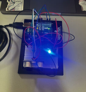
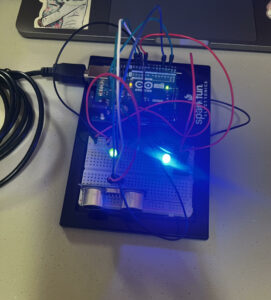
Video:
Code:
const int led0 = 3;
const int led1 = 5;
const int photoResistor = A1;
const int potentiometer = A0;
const int buttonPin = 2;

void setup() {
  Serial.begin(9600);
  pinMode(led0, OUTPUT);
  pinMode(led1, OUTPUT);
  pinMode(buttonPin, INPUT); // sets the button as an input device
}

void loop() {
  int lightValue = analogRead(photoResistor);
  int potValue = analogRead(potentiometer);
  int delayTime = map(potValue, 0, 1023, 50, 1000);
  int buttonState = digitalRead(buttonPin);

  Serial.print("Light Value: ");
  Serial.println(lightValue);

  // Analog control of red LED using potentiometer
  int brightness = map(potValue, 0, 1023, 0, 255);
  analogWrite(led0, brightness);

  // Digital control of green LED using a button
  if (buttonState == HIGH) {
    digitalWrite(led1, HIGH);
  } else {
    digitalWrite(led1, LOW);
  }

  // Additional feature using the photoresistor to change the behavior based on light
  if (lightValue < 300) {
    // When light levels are low, flash the green LED rapidly.
    digitalWrite(led1, HIGH);
    delay(100); // Short delay for rapid flash
    digitalWrite(led1, LOW);
    delay(100); // Continue rapid flash
  }
}
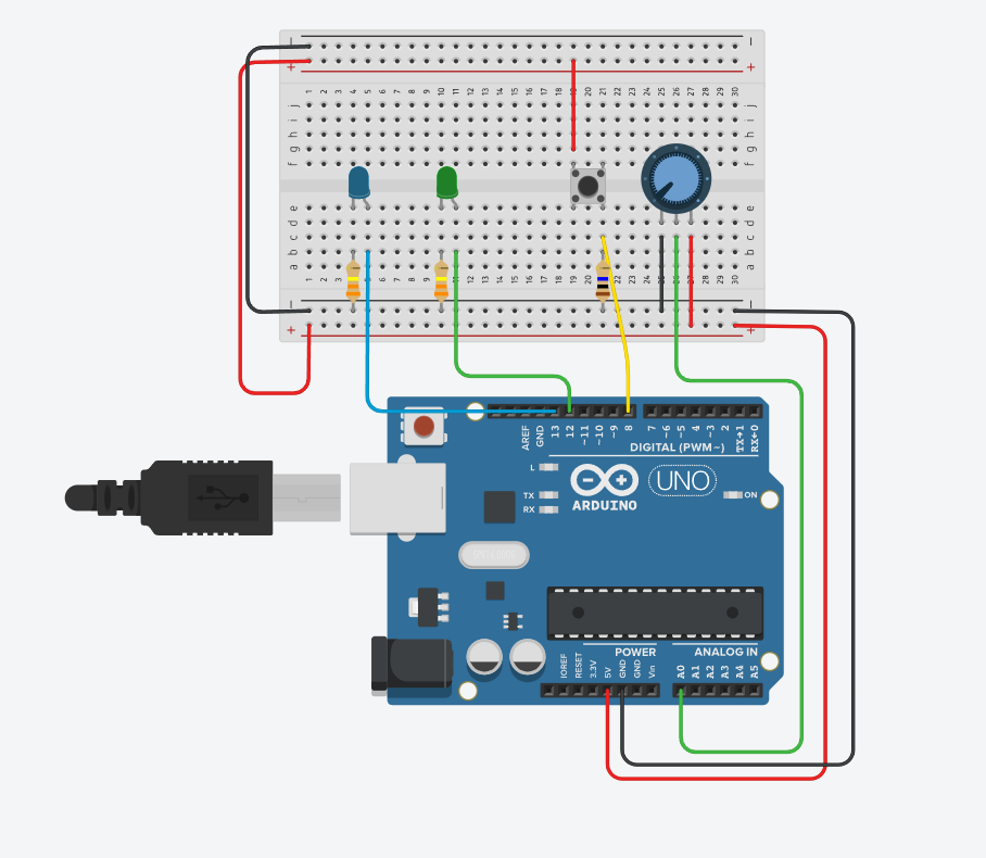
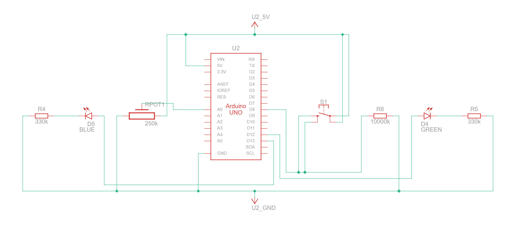
The code controls two LEDs based on inputs from a combination of analog and digital sensors, resulting in an interactive and dynamic output that depends on environmental conditions and user interaction.
- Red LED (Analog Control): The brightness of the red LED is directly controlled by a potentiometer. As the user adjusts the potentiometer, the red LED’s brightness varies smoothly from completely off to fully bright. This provides a visual representation of the analog input value, allowing users to see a direct correlation between the potentiometer’s position and the LED’s intensity.
- Green LED (Digital Control): The state of the green LED is controlled by a photoseisitor. Pressing photoresistor turns the LED on, and releasing it turns the LED off. This simple binary control mimics typical digital behaviors in electronics, where a switch controls a circuit’s on/off state.
- Additional Behavior with Photoresistor: When it gets dark, the green LED automatically starts flashing rapidly to signal a change in light conditions, overriding the button control.