Concept:
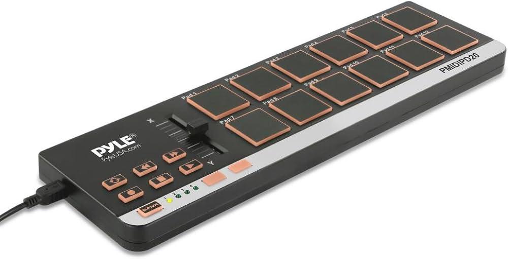
The concept of this project was to create a mini drum pad, or what is equivalent to one, with the hardware we have available. The device would use buttons to trigger different buzzer sounds, mimicking the functionality of a traditional drum pad. Each button on the device would correspond to a different sound, with the frequency of these sounds adjustable via a potentiometer. This allows the user to modify the pitch of the tones.
Code:
// Defining pins assignments for buttons and buzzers
const int buttonPin1 = 2;
const int buttonPin2 = 3;
const int buttonPin3 = 4;
// Coded with the Aid of ChatGPT
const int buttonPin4 = 5; // Monitoring and playbacks button
// Coded with the Aid of ChatGPT
const int buzzerPin1 = 8;
const int buzzerPin2 = 9;
const int buzzerPin3 = 10;
const int potPin = A0; // Potentiometer connected to A0 for frequency control

// Variables to manage button states and debounce timing
int buttonState1 = 0;
int lastButtonState1 = 0;
int buttonState2 = 0;
int lastButtonState2 = 0;
int buttonState3 = 0;
int lastButtonState3 = 0;
int buttonState4 = 0;
int lastButtonState4 = 0;

unsigned long lastDebounceTime1 = 0;
unsigned long lastDebounceTime2 = 0;
unsigned long lastDebounceTime3 = 0;
unsigned long lastDebounceTime4 = 0;
unsigned long debounceDelay = 50; // Debounce delay in milliseconds

// Struct to hold buzzer activation data including the pin and frequency
struct BuzzerAction {
  int buzzerPin;
  int frequency;
};

// Coded with the Aid of ChatGPT
BuzzerAction record[100]; // Array to store each buzzer activation
int recordIndex = 0; // Index for recording array
//Coded with the Aid of ChatGPT

void setup() {
  // Initialize all button and buzzer pins
  pinMode(buttonPin1, INPUT);
  pinMode(buttonPin2, INPUT);
  pinMode(buttonPin3, INPUT);
// Coded with the Aid of ChatGPT
  pinMode(buttonPin4, INPUT);
// Coded with the Aid of ChatGPT
  pinMode(buzzerPin1, OUTPUT);
  pinMode(buzzerPin2, OUTPUT);
  pinMode(buzzerPin3, OUTPUT);
  pinMode(potPin, INPUT); // Setups potentiometer pin as input
}

void loop() {
  // Reads current state of buttons
  int reading1 = digitalRead(buttonPin1);
  int reading2 = digitalRead(buttonPin2);
  int reading3 = digitalRead(buttonPin3);
// Coded with the Aid of ChatGPT
  int reading4 = digitalRead(buttonPin4);
// Coded with the Aid of ChatGPT
  int potValue = analogRead(potPin); // Reads potentiometer value
  int frequency = map(potValue, 0, 1023, 200, 2000); // Maps potentiometer value to frequency range

  // Handle button 1 press and recording
  debounceAndRecord(reading1, &lastButtonState1, &buttonState1, &lastDebounceTime1, buzzerPin1, frequency);

  // Handle button 2 press and recording
  debounceAndRecord(reading2, &lastButtonState2, &buttonState2, &lastDebounceTime2, buzzerPin2, frequency);

  // Handle button 3 press and recording
  debounceAndRecord(reading3, &lastButtonState3, &buttonState3, &lastDebounceTime3, buzzerPin3, frequency);

  // Handles button 4 for playback
  if (reading4 != lastButtonState4) {
    lastDebounceTime4 = millis();
  }
  if ((millis() - lastDebounceTime4) > debounceDelay) {
    if (reading4 != buttonState4) {
      buttonState4 = reading4;
      if (buttonState4 == HIGH) {
        for (int i = 0; i < recordIndex; i++) {
          // Play each recorded buzzer action with the specific frequency recorded
          tone(record[i].buzzerPin, record[i].frequency, 200);
          delay(250); // Short delay between each buzzer action for clarity
        }
        recordIndex = 0; // Resets record index after playback
      }
    }
  }

  // Update last button states for next loop iteration
  lastButtonState1 = reading1;
  lastButtonState2 = reading2;
  lastButtonState3 = reading3;
  lastButtonState4 = reading4;
}
// Coded with the Aid of ChatGPT
// Function to handle button debouncing and recording buzzer actions
void debounceAndRecord(int reading, int *lastButtonState, int *buttonState, unsigned long *lastDebounceTime, int buzzerPin, int frequency) {
  if (reading != *lastButtonState) {
    *lastDebounceTime = millis(); // Reset debounce timer
  }
  if ((millis() - *lastDebounceTime) > debounceDelay) {
    if (reading != *buttonState) {
      *buttonState = reading; // Updates button state
      if (*buttonState == HIGH && recordIndex < sizeof(record) / sizeof(record[0])) {
        record[recordIndex++] = {buzzerPin, frequency}; // Records the buzzer activation
        tone(buzzerPin, frequency, 200); // Plays buzzer at recorded frequency
      }
    }
  }
  *lastButtonState = reading; // Updates last button state for debouncing
// Coded with the Aid of ChatGPT
}
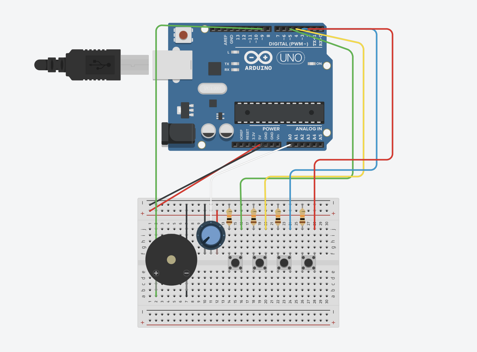
Hardware Configuration: The system is designed with four button inputs and three buzzer outputs. Additionally, a potentiometer is used to control the frequency of the buzzer sounds. Button Functionality: Buttons 1 to 3 are connected to buzzers and are responsible for triggering sounds with variable frequencies determined by the potentiometer. Button 4 is designated for playback. It plays back a sequence of sounds that have been recorded based on earlier interactions with buttons 1 to 3.
Frequency Control: The frequency of the sounds is dynamically adjusted using a potentiometer. The analog value from the potentiometer is mapped to a specified frequency range (200 Hz to 2000 Hz), which determines how the buzzers sound.
Debouncing: To ensure reliable button press detection without noise interference, the code implements debouncing logic. This involves measuring the time since the last button state change and updating the state only if this interval exceeds a predefined threshold (50 milliseconds).
Recording and Playback (Aided by ChatGPT)
Recording: When a button (1 to 3) is pressed, the action (which buzzer is activated and at what frequency) is recorded in an array. This includes storing both the pin of the buzzer and the frequency at which it was activated.
Playback: When button 4 is pressed, the system iterates over the recorded actions and plays them sequentially. Each action triggers the corresponding buzzer to sound at the recorded frequency for a short duration.
Loop and Functions: The main loop continuously checks the state of each button and the potentiometer, updating the frequency accordingly. A helper function, debounceAndRecord, is used to handle the logic
Video of Project:
Reflection and ideas for future work or improvements:
Integrating a small display screen would significantly improve its functionality, further enhancing the project. This screen would provide real-time visual feedback on button presses and frequency outputs, allow users to scroll through and select different sounds or presets, and serve as a simple interface for directly programming the device.
The potential for further development and refinement holds exciting prospects. The integration of a display screen and the addition of more customizable buttons are immediate steps that will enhance the device’s usability and versatility. Further innovations could include wireless connectivity for easy integration with other music production software or the addition of sensors to enable gesture-based controls, which would offer an even more dynamic and immersive user experience.
Several key insights stand out after reflecting on what this project has taught us. First, the practical challenges of hardware interfacing taught us the importance of robust design and a solid plan for creating it. There is also a need for effective wire management and physical housing to enhance device durability and aesthetics.
Looking Ahead:
Overall, this project resulted in a functional and entertaining product and served as a significant learning experience, underscoring the importance of patience, precision, and creativity in making it happen. These lessons will guide further improvements and innovations in our future projects.