Week 10 – Reading

The web article entitled “A Brief Rant on the Future of Interaction Design” evokes a range of emotions in its readers. Initially, the video produced by Microsoft appeared flawless and aligned with the reader’s expectations of the future. However, the subsequent discussion on tools and interaction components prompted a reevaluation of what constitutes an improvement. The author effectively illustrates this point by comparing a hammer to human interaction, emphasizing that our hands are the primary component in tangible interactions. The author argues that despite the underlying technology, our interactions have slightly improved. This argument is supported by the concept of “tactile richness.”

While I generally agree with the author’s assertion that corporations often exaggerate the advancements in their products, I find the notion that tactile richness can be fully extracted from non-tangible elements to be flawed. Furthermore, the development of haptics and sensors like gyroscopes has enabled the creation of products such as smart glass, which have revolutionized human-computer interaction by incorporating gestures like head tilts, voice commands, and other active inputs. These advancements significantly surpass the limitations of traditional touchscreens. Consequently, I believe they contradict the author’s claim that tangible improvements are not being made.

Nevertheless, I acknowledge that in terms of manipulation and tactile richness, the emphasis on branding and hype may not accurately reflect the actual level of advancement.

Regarding the other reading, it sent me into a frenzy full of laughter. The majority of the disagreements and counterarguments I had, such as the use of gestures, voice, and tangible-non-tangible elements, were addressed in this follow-up response. I acknowledge that the writer possesses a distinct perception and perspective, and how they employ certain claims to support their arguments, such as densely nerve-covered finger tips and their correlation with brain development. However, I firmly believe that it ultimately reduces to the concept of interpretivism. How we define technology. For someone completely unfamiliar with the concept of a stylus, they would likely find little to utilize or develop with. In their eyes, a transition from a stylus to an OLED glass display would appear more advantageous and innovative. Personally, I grew up with a Nintendo DS that came with a stylus. The next generation of PS-Vita captured my attention, and since then, I have never touched that Nintendo. The tool we use to amplify certain phenomena—for some, the desired amplification may vary. Therefore, I firmly believe that our responses differ. Furthermore, considering the significant advancements in technology since the publication of this article fourteen years ago, I suspect that the author may simply be making certain exceptions.

Week 10 – Production Assignment

Musical Instrument

Introduction:

An instrument is something that helps us humans either measure the data or produce it. For this assignment, we were supposed to build a musical instrument in a group of two. Given my health challenges, I was unable to team up with anyone, and decided to pursue it on my own. I started off by asking the most fundamental question – “What is a musical instrument ? ” Something that plays sound when triggered? Or something that plays sound on its own? What kind of sound? How many sounds? It is when after pondering on the philosophy of a musical device, I questioned my surroundings. I don’t happen to have a dorm mate, and very less likely do I get to socialize with others around the campus. Sometimes the thoughts themselves get too loud that I start second guessing my self. This is where the eureka moment came in! A musical device that talks to me – interacts with my as if a roommate for instance would have done. To start off with basics, a greeting or a salutation would have had sufficed as well. There and then the idea of ‘Welcominator’ was born!

Concept and design:

After having decided upon what to make and accomplish, I got down to work. The basic logic of ‘Welcominator’ would involve use of a trigger mechanism which would recognize the moment I settle inside my room, and a speaker, alongside a digital and an analogue switch to trigger and adjust response.

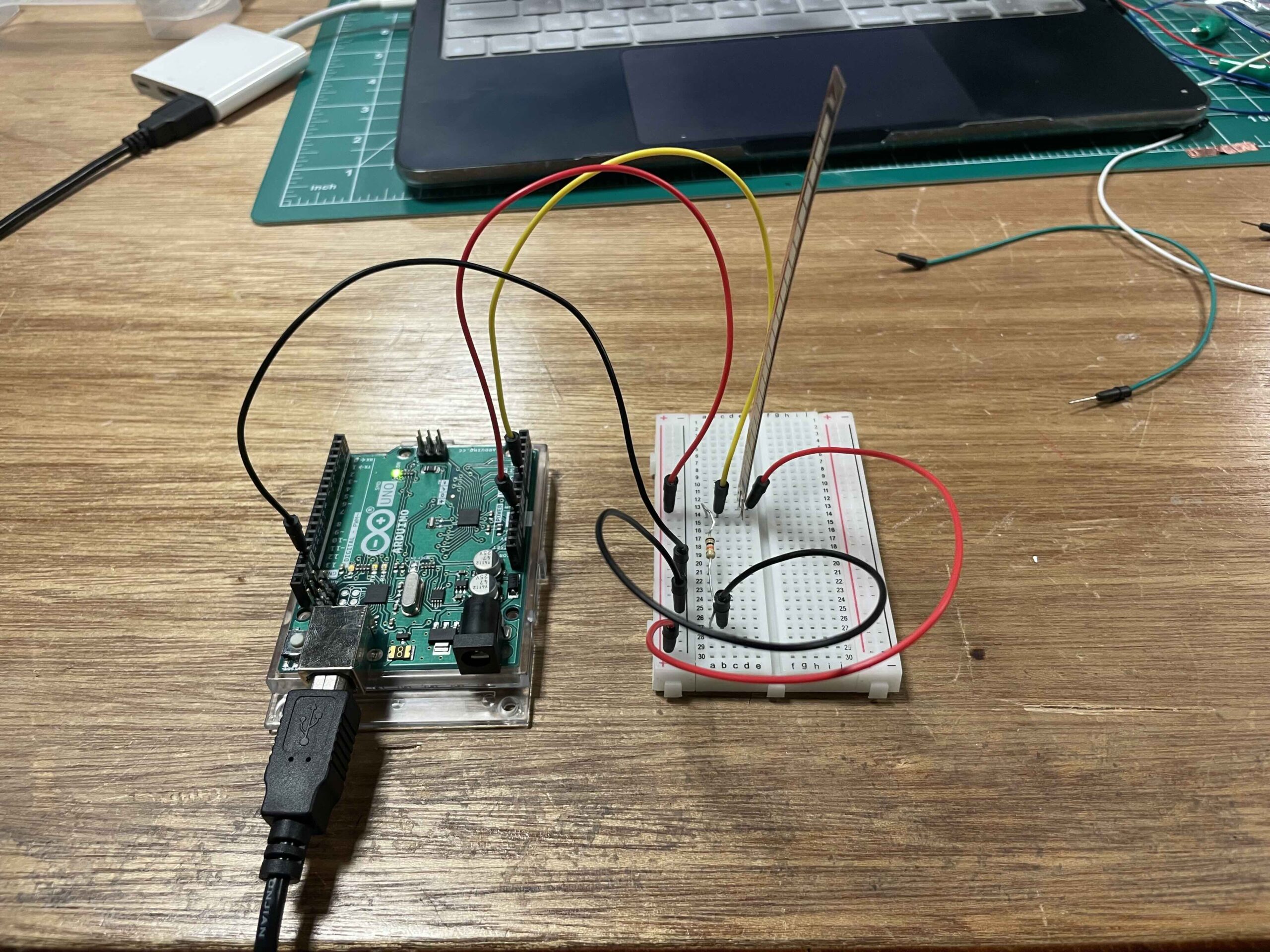
For the digital sensor / switch I decided to use the FSR sensor (Force Sensing Resistor). This sensor reduces the resistance with greater pressure applied, and by logic qualifies for the analogue sensor. However, the basic concept to this instrument was me putting down my items such as my watch as soon as I enter and settle down inside my dorm. Thus, two FSR sensors were used for greater surface area, and the value read by these sensors was read using digitalRead. Therefore, acting as a switch, the value of 1 or 0 was only read.

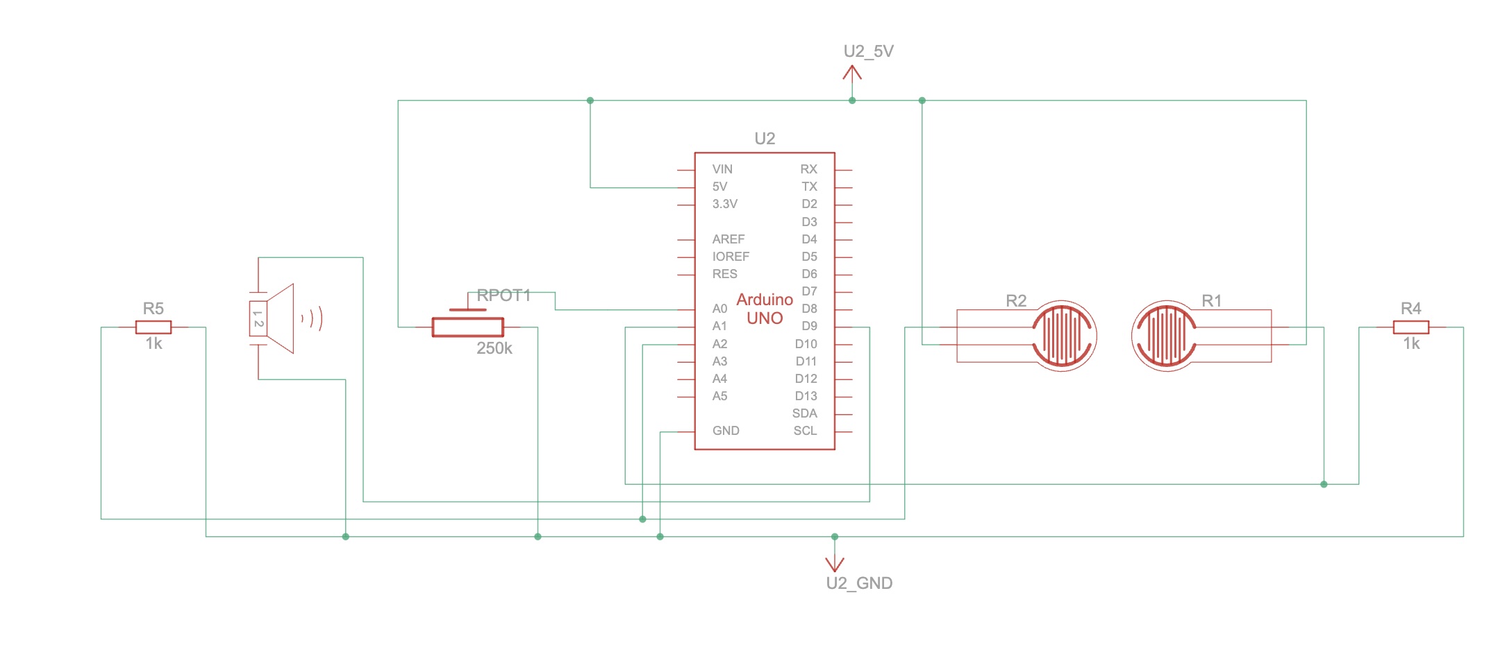
As for the analogue sensor, the potentiometer was used. The potentiometer in this case was not used to adjust the volume, but rather to choose between the audio tracks. The code written would select which sound to play depending on the current fed in by the wiper toward the A0 pin on the Arduino. The schematic and sketch below show the connection and logical mapping of the ciruit:


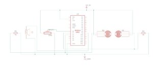
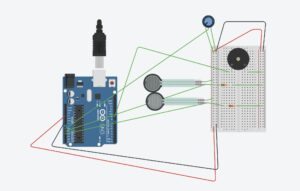
The buzzer or the speaker takes voltage signals from pin 9, whilst the digitalRead performed on FSR sensor is sent to pin A1 and A2 respective of the sensor.  It is an active buzzer and hence can play different sound tunes.

Code:

//crucial file added to understand how pitches and notes work
#include "pitches.h"

#define BUZZER_PIN 9
#define POT_PIN A0
#define SENSOR1_PIN A1
#define SENSOR2_PIN A2

bool isPlaying = false;

// godfather
int godfather_melody[] = {
  NOTE_E4, NOTE_A4, NOTE_C5, NOTE_B4, NOTE_A4, NOTE_C5, NOTE_A4, NOTE_B4, NOTE_A4, NOTE_F4, NOTE_G4,
  NOTE_E4, NOTE_E4, NOTE_A4, NOTE_C5,
  NOTE_B4, NOTE_A4, NOTE_C5, NOTE_A4, NOTE_C5, NOTE_A4, NOTE_E4, NOTE_DS4,
  NOTE_D4, NOTE_D4, NOTE_F4, NOTE_GS4,
  NOTE_B4, NOTE_D4, NOTE_F4, NOTE_GS4,
  NOTE_A4, NOTE_C4, NOTE_C4, NOTE_G4,
  NOTE_F4, NOTE_E4, NOTE_G4, NOTE_F4, NOTE_F4, NOTE_E4, NOTE_E4, NOTE_GS4,
  NOTE_A4
};

int godfather_durations[] = {
  8, 8, 8, 8, 8, 8, 8, 8, 8, 8, 8,
  2, 8, 8, 8,
  8, 8, 8, 8, 8, 8, 8, 8,
  2, 8, 8, 8,
  2, 8, 8, 8,
  2, 8, 8, 8,
  8, 8, 8, 8, 8, 8, 8, 8,
  2
};

// nokia tune
int nokia_melody[] = {
  NOTE_E5, NOTE_D5, NOTE_FS4, NOTE_GS4, 
  NOTE_CS5, NOTE_B4, NOTE_D4, NOTE_E4,
  NOTE_B4, NOTE_A4, NOTE_CS4, NOTE_E4,
  NOTE_A4
};

int nokia_durations[] = {
  8, 8, 8, 8,
  8, 8, 8, 8,
  8, 8, 8, 8,
  8
};


void setup() {
  pinMode(BUZZER_PIN, OUTPUT);
  pinMode(SENSOR1_PIN, INPUT);
  pinMode(SENSOR2_PIN, INPUT);
  pinMode(POT_PIN, INPUT);
}


void loop() {
  int potValue = analogRead(POT_PIN);
  bool useGodfather = potValue < 512;  // Left side (low) pot = Godfather, Right (high) = Nokia

  int sensor1Value = digitalRead(SENSOR1_PIN);
  int sensor2Value = digitalRead(SENSOR2_PIN);

  bool sensorTriggered1 = sensor1Value == HIGH;
  bool sensorTriggered2 = sensor2Value == HIGH;

  if ((sensorTriggered1 || sensorTriggered2) && !isPlaying) { // checks if no music is playing and either of the sensor trigger is recorded for
    isPlaying = true;
    if (useGodfather) {
      playMelody(godfather_melody, godfather_durations, sizeof(godfather_melody) / sizeof(int));
    } else {
      playMelody(nokia_melody, nokia_durations, sizeof(nokia_melody) / sizeof(int));
    }
    isPlaying = false;
  }
}

//function for playing melody
void playMelody(int melody[], int durations[], int length) {
  for (int i = 0; i < length; i++) {
    int noteDuration = 1000 / durations[i];
    tone(BUZZER_PIN, melody[i], noteDuration);
    delay(noteDuration * 1.2); // time duration added betnween notes to make it seem buttery smooth.
    noTone(BUZZER_PIN);
  }
}
// pitches.h
#define REST 0

#define NOTE_B0 31
#define NOTE_C1 33
#define NOTE_CS1 35
#define NOTE_D1 37
#define NOTE_DS1 39
#define NOTE_E1 41
#define NOTE_F1 44
#define NOTE_FS1 46
#define NOTE_G1 49
#define NOTE_GS1 52
#define NOTE_A1 55
#define NOTE_AS1 58
#define NOTE_B1 62
#define NOTE_C2 65
#define NOTE_CS2 69
#define NOTE_D2 73
#define NOTE_DS2 78
#define NOTE_E2 82
#define NOTE_F2 87
#define NOTE_FS2 93
#define NOTE_G2 98
#define NOTE_GS2 104
#define NOTE_A2 110
#define NOTE_AS2 117
#define NOTE_B2 123
#define NOTE_C3 131
#define NOTE_CS3 139
#define NOTE_D3 147
#define NOTE_DS3 156
#define NOTE_E3 165
#define NOTE_F3 175
#define NOTE_FS3 185
#define NOTE_G3 196
#define NOTE_GS3 208
#define NOTE_A3 220
#define NOTE_AS3 233
#define NOTE_B3 247
#define NOTE_C4 262
#define NOTE_CS4 277
#define NOTE_D4 294
#define NOTE_DS4 311
#define NOTE_E4 330
#define NOTE_F4 349
#define NOTE_FS4 370
#define NOTE_G4 392
#define NOTE_GS4 415
#define NOTE_A4 440
#define NOTE_AS4 466
#define NOTE_B4 494
#define NOTE_C5 523
#define NOTE_CS5 554
#define NOTE_D5 587
#define NOTE_DS5 622
#define NOTE_E5 659
#define NOTE_F5 698
#define NOTE_FS5 740
#define NOTE_G5 784
#define NOTE_GS5 831
#define NOTE_A5 880
#define NOTE_AS5 932
#define NOTE_B5 988
#define NOTE_C6 1047
#define NOTE_CS6 1109
#define NOTE_D6 1175
#define NOTE_DS6 1245
#define NOTE_E6 1319
#define NOTE_F6 1397
#define NOTE_FS6 1480
#define NOTE_G6 1568
#define NOTE_GS6 1661
#define NOTE_A6 1760
#define NOTE_AS6 1865
#define NOTE_B6 1976
#define NOTE_C7 2093
#define NOTE_CS7 2217
#define NOTE_D7 2349
#define NOTE_DS7 2489
#define NOTE_E7 2637
#define NOTE_F7 2794
#define NOTE_FS7 2960
#define NOTE_G7 3136
#define NOTE_GS7 3322
#define NOTE_A7 3520
#define NOTE_AS7 3729
#define NOTE_B7 3951

The code above addresses the logic and the pitches.h is another file used for defining and storing the notes that are used by our program. Code for the pitches and the sounds for ‘Godfather theme’ and ‘Nokia ‘ tune were taken from Arduino Project HUB website .

Both FSR sensor trigger HIGH or LOW value, and if potentiometer is registering lower voltage, then Godfather theme plays, and when it registers higher voltage, the Nokia tune plays. Once it ends, it sets the isPlaying state to false. This is to avoid interruption. Last but not the least, chatgpt was used to order pitches.h file as coding it myself would have been impossible.


Challenges:

One and the only challenge I faced was the FSR registering high, even when there was no pressure being applied. This led me to do some researching. Turns out that sometimes inaccuracy and condition of the sensor renders false positives. Hence, I used a resistor connection with the sensor and ground to get rid of the  tingling current, and register high only when a solid threshold was provided. An led was attached before the buzzer, for visual aesthetics and for indication that current was going through the buzzer. Initially the buzzer would work as well. This led me to code and find the bug in wrong pin assignment

Demo:

Future Revisions:

For future revision I intend to add multiple songs, FSR sensors, and an array of leds which can mimic the sound pattern.

Week 12 — Final Progress Report

Final Idea

After lots of thought (in which initially, I wanted it to be a I’ve settled on a concept for a game titled “Did You Eat My Chips?”. The premise is a semi-thriller, played in a lighthearted tone, where the objective is to consume chips surreptitiously while avoiding detection by your slime sibling. My aim was to strike a balance, creating an experience that is engaging without being overtly frightening, yet distinct from typical game scenarios. This approach was driven by the desire to incorporate a pulse sensor, using it to gauge a player’s physiological response during time-sensitive, high-pressure(?) situations within the game and observe the impact of these moments on their state. This was largely inspired by my experience growing up with my sister where we would sneakily eat each other’s food; it always felt like a thriller movie.

Progress

So far, I’ve been busy sketching out some ideas for how the game will look. I’ve been doing some image drafts in Figma and Procreate to get a feel for the design style and what I want to aim for when I start building things in p5.js. On the hardware side, I’ve also been playing around with the flex sensor. That’s going to be the main way you control the game, so I’m just getting the hang of how it works and how to use it.

Visuals

What is left?

I still have to test the pulse sensor and see how to interact with the game. I have to borrow it from the IM lab so I’ll be testing that out today.

Week 12: Final Project Proposal

After a lot of deliberation and brainstorming, I am happy to report that I have solidified my final project concept. I will be producing an interactive piece of art that aims to tell the story of international students in the US who are being targeted by the current political situation.

My work will allow anyone to participate by scanning a QR code, which will direct them to my p5.js sketch which shuffles through images–coordinated real-time with text on screen transcribing details. The p5.js sketch will connect to a websocket running on my server, which provides control information for the piece.

Finally, a panel at the front of the installation will include controls, which allow viewers to adjust the playback of the art, including speed and effects. A diagram of the architecture is attached below.


Final project finalized concept | Handdrawn shape guessing using AI

Let me walk you through my journey of planning an Arduino integration for my existing Python-based drawing application. TBH the Arduino implementation isn’t complete yet, but the documentation and planning phase has been fascinating!

The Current State: A Digital Drawing Assistant

Before diving into the Arduino part, let me elabroate about the current state of the application. My app is built with Python and PyQt5, featuring:

      • A digital canvas for freehand drawing
      • Color selection and brush size options
      • An AI assistant that can recognize what you’ve drawn (with a fun, playful personality)
      • The ability to save, load, and organize drawings

The AI assistant is my favorite part—it has this quirky personality that makes drawing more entertaining. It’ll say things like “That’s obviously a circle! Van Gogh would approve!” or “I’m as lost as a pixel in a dark room. Can you add more detail?” of course the hardest part was to actually come up with those lines.


The Arduino Part

The next phase of development involves adding physical controls through an Arduino. Here’s what I’m planning to implement:

      • Joystick control for moving the digital cursor and drawing
      • Physical buttons for clearing the canvas, changing colors, and triggering the AI assistant
      • Visual and audio feedback to enhance the experience

The beauty of this integration is how it bridges the digital-physical gap.  I am trying to reach the peak of interactivity that I can think of, and I think having an interactive AI system is as far as I can, with my current knowledge, achieve and implement.

Vision of the structure

app,py/

├── main.py (needs to be updated)
├── arduino_integration.py (not yet there)
├── test_arduino.py (not yet there)
├── config.py

├── core/
│ ├── __init__.py
│ ├── conversation.py
│ ├── drawing_manager.py
│ ├── recognition.py
│ ├── tts.py
│ └── arduino_controller.py (not yet there)

├── data/
│ ├── __init__.py
│ ├── database.py
│ ├── history.py
│ └── user_settings.py

├── ui/
│ ├── __init__.py
│ ├── main_window.py
│ ├── canvas.py
│ ├── toolbar.py
│ ├── settings_dialog.py
│ └── training_dialog.py

├── Arduino/
│ └── DrawingAI_Controller.ino (not yet there)

└── sounds/ (not set, only palceholders)
├── connect.wav
├── disconnect.wav
├── clear.wav
├── color.wav
└── guess.wav

Challenges

I want to have the joystick and buttons on a  plain wooden plank and in a container to hold it in place, and the buttons not on a breadboard but actually on a physical platform that makes everyting looks nicer, to be honest i am so lost with that, but we will see how things go.

Very very late assignment 11 submission


Sorry for my late submission , I was facing a lot of problems that I was not aware how to solve, apparently my browser (Opera GX) does not support p5 – arduino communication, it took me ages to realize, and I compensated with putting extra effort into my assignment.

1)


2)

3)

// bounce detection and wind control
// pin setup
const int potPin = A0;  // pot for wind control
const int ledPin = 9;   // led that lights up on bounce

// vars
int potValue = 0;       // store pot reading
float windValue = 0;    // mapped wind value
String inputString = ""; // string to hold incoming data
boolean stringComplete = false; // flag for complete string
unsigned long ledTimer = 0;      // timer for led
boolean ledState = false;        // led state tracking
const long ledDuration = 200;    // led flash duration ms

void setup() {
  // set led pin as output
  pinMode(ledPin, OUTPUT);
  
  // start serial comm
  Serial.begin(9600);
  
  // reserve 200 bytes for inputString
  inputString.reserve(200);
}

void loop() {
  // read pot val
  potValue = analogRead(potPin);
  
  // map to wind range -2 to 2
  windValue = map(potValue, 0, 1023, -20, 20) / 10.0;
  
  // send wind value to p5
  Serial.print("W:");
  Serial.println(windValue);
  
  // check for bounce info
  if (stringComplete) {
    // check if it was a bounce message
    if (inputString.startsWith("BOUNCE")) {
      // turn on led
      digitalWrite(ledPin, HIGH);
      ledState = true;
      ledTimer = millis();
    }
    
    // clear string
    inputString = "";
    stringComplete = false;
  }
  
  // check if led should turn off
  if (ledState && (millis() - ledTimer >= ledDuration)) {
    digitalWrite(ledPin, LOW);
    ledState = false;
  }
  
  // small delay to prevent serial flood
  delay(50);
}

// serial event occurs when new data arrives
void serialEvent() {
  while (Serial.available()) {
    // get new byte
    char inChar = (char)Serial.read();
    
    // add to input string if not newline
    if (inChar == '\n') {
      stringComplete = true;
    } else {
      inputString += inChar;
    }
  }
}


Finalized concept for the project

Finalized concept for the project

My final project helps users, especially beginners, to learn how to play the piano and learn how to jam to the blues music style. I created a mini-piano consisting of 2 octaves plus one key (spanning notes C4 to C6), which is a welcoming size for beginners. A visualization of a piano is displayed on the p5js sketch, which can be helpful for the piano player to see an animated pressed key and listen to the relevant audio for that pressed key.

The piano is color-coded by note, so that note “C” is white, “D” is orange, “E” is red, “F” is blue and so on. This was a deliberate choice because seeing different colours on the piano can help users familiarize themselves with the positions of the keys over time. Additionally, I used this presentation slide deck with instructions to play the notes, color-coded, in order (example in Fig. 1). Thus, as users see the color-coded notes on the presentation and try to follow it, they could more quickly and easily match it to the note on the physical piano that they should play.

Instructions to Play, In Left-Right Order, the Color-Coded Notes
Fig. 1. Instructions to Play, In Left-Right Order, the Color-Coded Notes

Design and description of what your Arduino program will do with each input and output and what it will send to and/or receive from P5

  • Inputs:
    • Force Sensitive Resistors (FSR) – Arduino program receives note state based on FSR readings vs press thresholds. If the readings meet the conditions, send to p5.
    • Push buttons – Arduino program receives note state based on reading on whether button is pressed.
  • No outputs

Design and description of what P5 program will do and what it will send to and/or receive from Arduino

In the communication from Arduino to p5, a string is sent line-by-line containing note name, followed by “=”, followed by note state (either 0 or 1 depending on if it’s considered pressed or not). activeSerialNoteStates is an important variable that stores the latest state (0 or 1) received from Arduino for each note name. Based on the current state of a particular key in activeSerialNoteStates, the handlePressEvent() and display() for that key is called.

Progress

Tomorrow and this Sunday, I could try to work on building the circuit.

References:

  • Blues scale, E blues scale: https://www.youtube.com/watch?v=CjJwxtahGtw
  • Major vs Minor Blues scales: https://www.youtube.com/watch?v=WWEchKvZwdE
  • Pentatonic scales and blues scales: https://www.youtube.com/watch?v=Vj-BOmKgdE4

Week 11- Final Project Preliminary Concept

Concept

For the final project I’ll be building a color memory game where the user sees colors generated at random by p5js and tries to match the colors by pressing arcade push buttons in the same order. And it gets tough as the game progresses. Every time the user gets it right a two-tiered trolley moves forward. The goal is to make the trolley/toy move as far as possible and close to the finish line within a short period of time.

Arduino and p5js

There will be serial communication between arduino and p5js in relaying the information concerning the color pressed (in arduino) against what has been displayed (on p5js) randomly. If there is a correct match between the two communication is sent back to the arduino to move the trolley forward. If not the p5js repeats the same pattern of colors previously displayed. There will also be a timer on the p5js screen to show the amount of time spent by the player.

Week 12 – Final Project Proposal : Canon Powered Cornhole Game

Introduction:

Growing up in a South Asian country, I consumed American Media – films,  documentaries, comedy skits, and even FOX News for my daily dose of reliable news. It was during this time that I happened to have been introduced to the carnival game of ‘Cornhole’  during a KSN-TV’s broadcast on Kansas country-side fair. A mix of basketball and golf with a southern dialect to it – I found it to be fascinating. It was so fascinating that when I was overwhelmed by so many ideas to choose from for this final project, I decided to go with a ‘Canon Powered’ Cornhole Game. Instead of tossing by hand, participants decide orientation in X and Y axis, and let the canon shoot out the corn bag. In our case, it would be a small sack filled with weight.


Amazon.com : Super Fun, Portable Mini Desktop Cornhole Set of 2. Coated Wood Boards with 4 Red 4 Blue Bags. Gift for Students, Office Employees or Work from Home. Simple Easy Tabletop

Canon:

The canon would be a 3d printed model. Not big, just about big as my Week 9’s canon. Yes, this is a continuation of that project! That was a candy canon that moved in X axis. This is a fully functional canon with loading and reloading capabilities!

The sketches below visualizes the working and highlights the basic design of the canon. The first one shows how to concept is imagined to be. The canon releases the inside barrel powered by an elastic material having stored the elastic potential energy. That potential energy is released and converted into kinetic energy. This kinetic energy and speed coupled with momentum results in impulse provided to the sack which turns its inertia to a trajectory.

The side view demonstrates the use of two motors, one oriented for x-axis movement and the other one for y-axis movement.

The supported stand on the left end with a claw-like  grappler helps keep the canon loaded. Upon trigger, it will release and let the tension of the elastic loose which will lead to forward release mechanism.

Arduino and P5 Program :

The movement of this canon will be controlled by gyroscope mounted on to gym-gloves. The gloves will also have the flex sensors, so that with hand tilt and movement, corresponding movement along x and y-axis will take place. When the hands are clenched , it will result to the release mechanism being triggered. A pressure sensor will be put underneath the hole/target to detect if the ball/sack has landed. The p5 program will first start off with a menu with  screen offering the user to play or go over instructions. This game will be both in virtual and real domain. The game will start with a 1 minute counter. For each corn in the hole, user will get response on the screen with animation and led will light up, while also points would increase.  When in reload state, the user won’t be able to move the robot, this is for convenience as to prevent user from mistakenly moving the robot while reloading. Once the game ends, the robot stops moving and the highscore displayed.

The arduino will control the movement of the three motors as an output signal (PWM), with last one being a servo, it will take input from the gyroscope and flex sensor for the controls. The Pressure sensor under the cornhole will trigger point system and this will be conveyed to the P5  program by and  after having read by the Arduino. The state of servo motor will be conveyed to the p5 program as well. In return, the p5 will communicate back the permission or the kill-switch condition to start or stop the program. It will process and display the state (i.e launch or reload), and will show the points alongside the timmer. I will add in safety nets too to prevent the machine from turning too much and breaking the structure/casing. Last but not the least, it will shutdown the connection between the gloves and the motors once the game has concluded.