Groupmates : Liya and Shamma
CONCEPT and working :
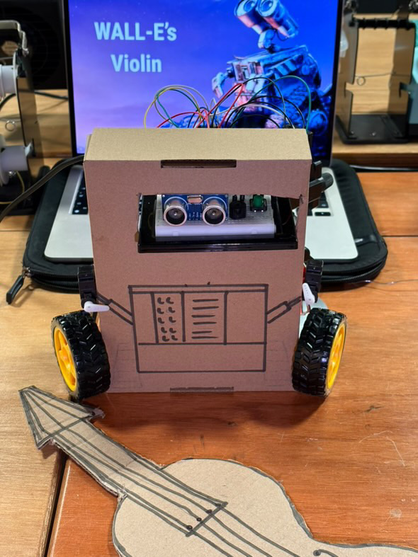
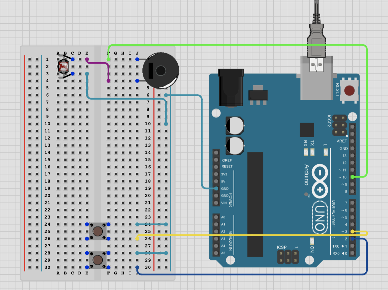
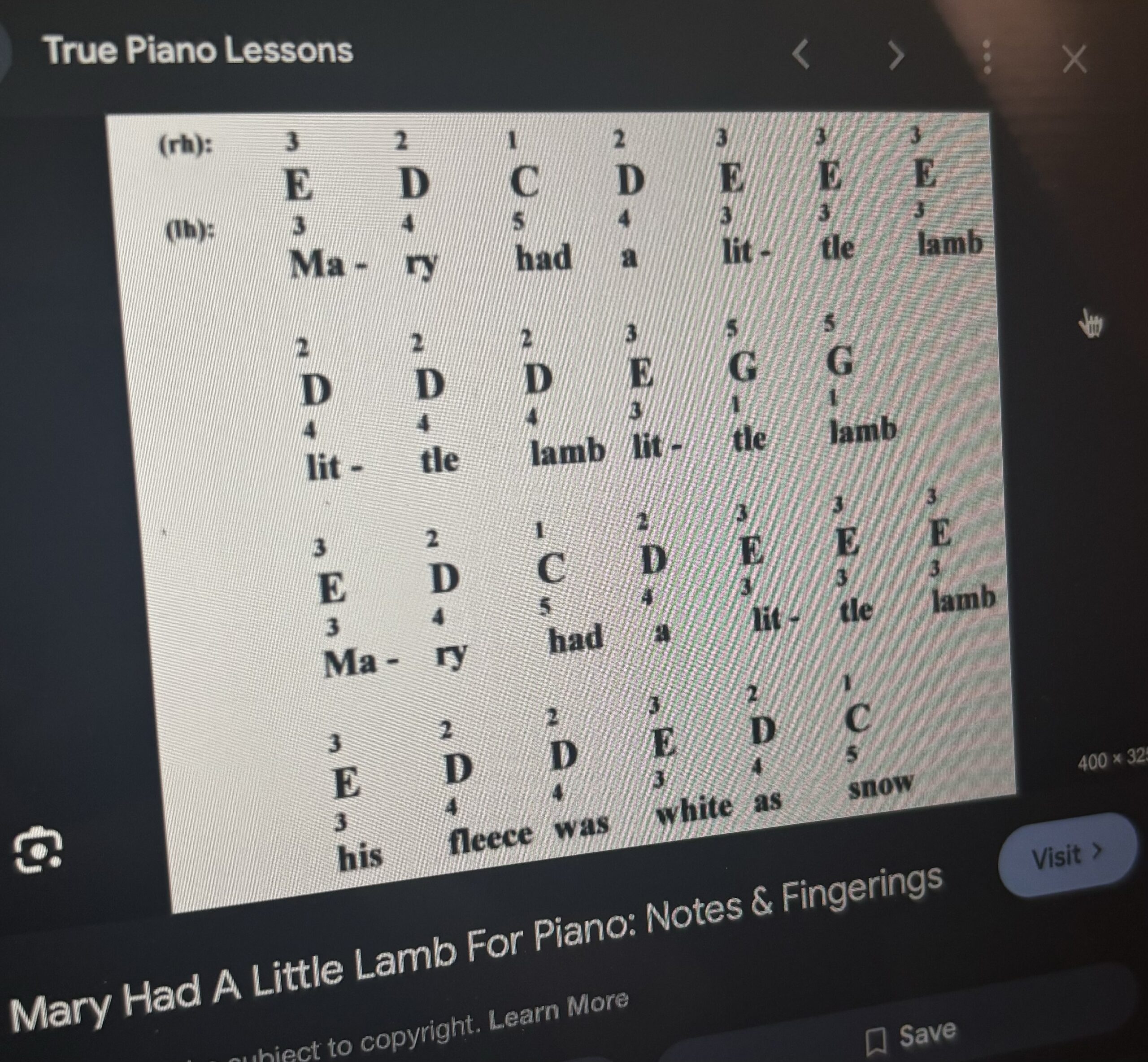
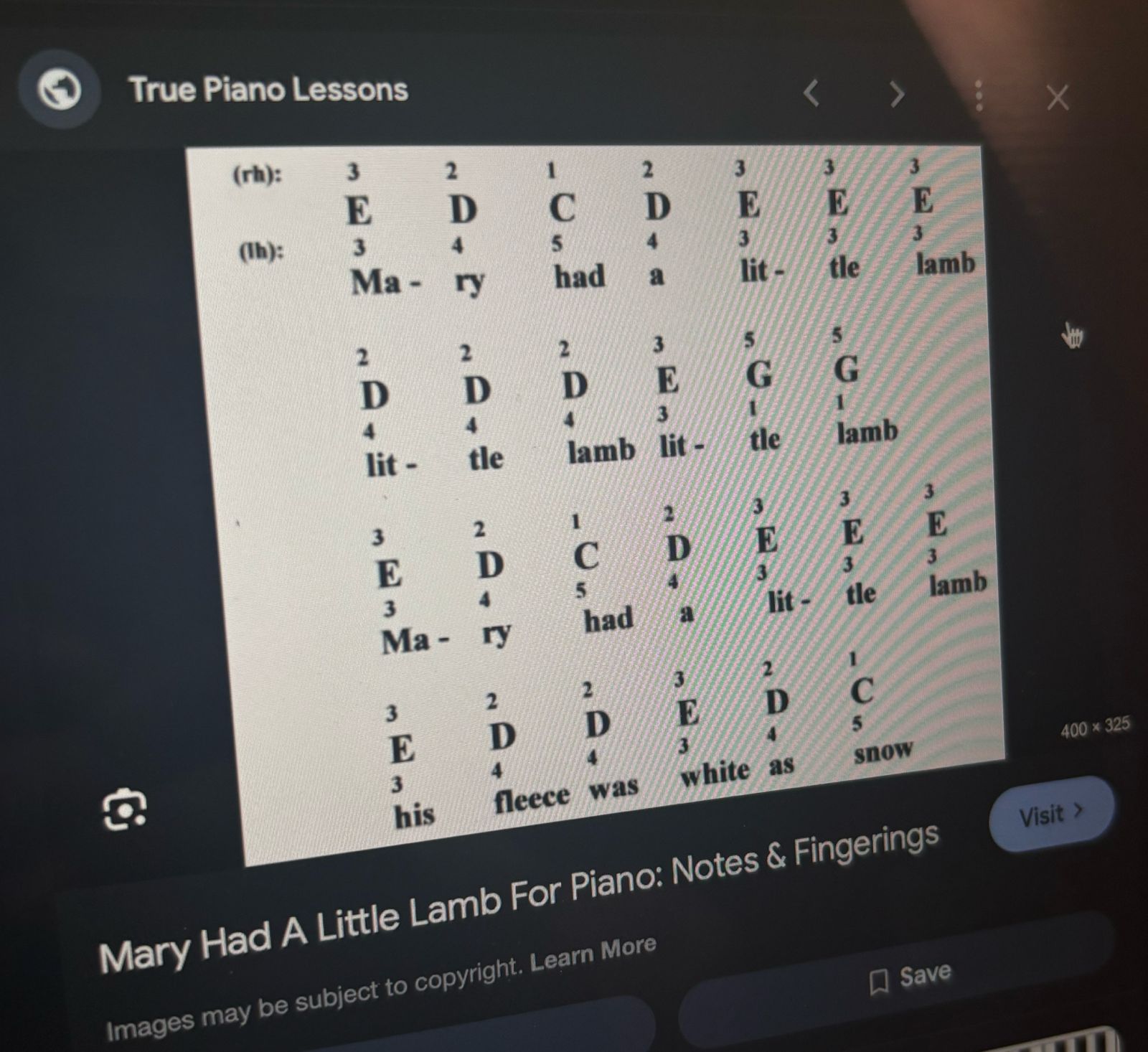
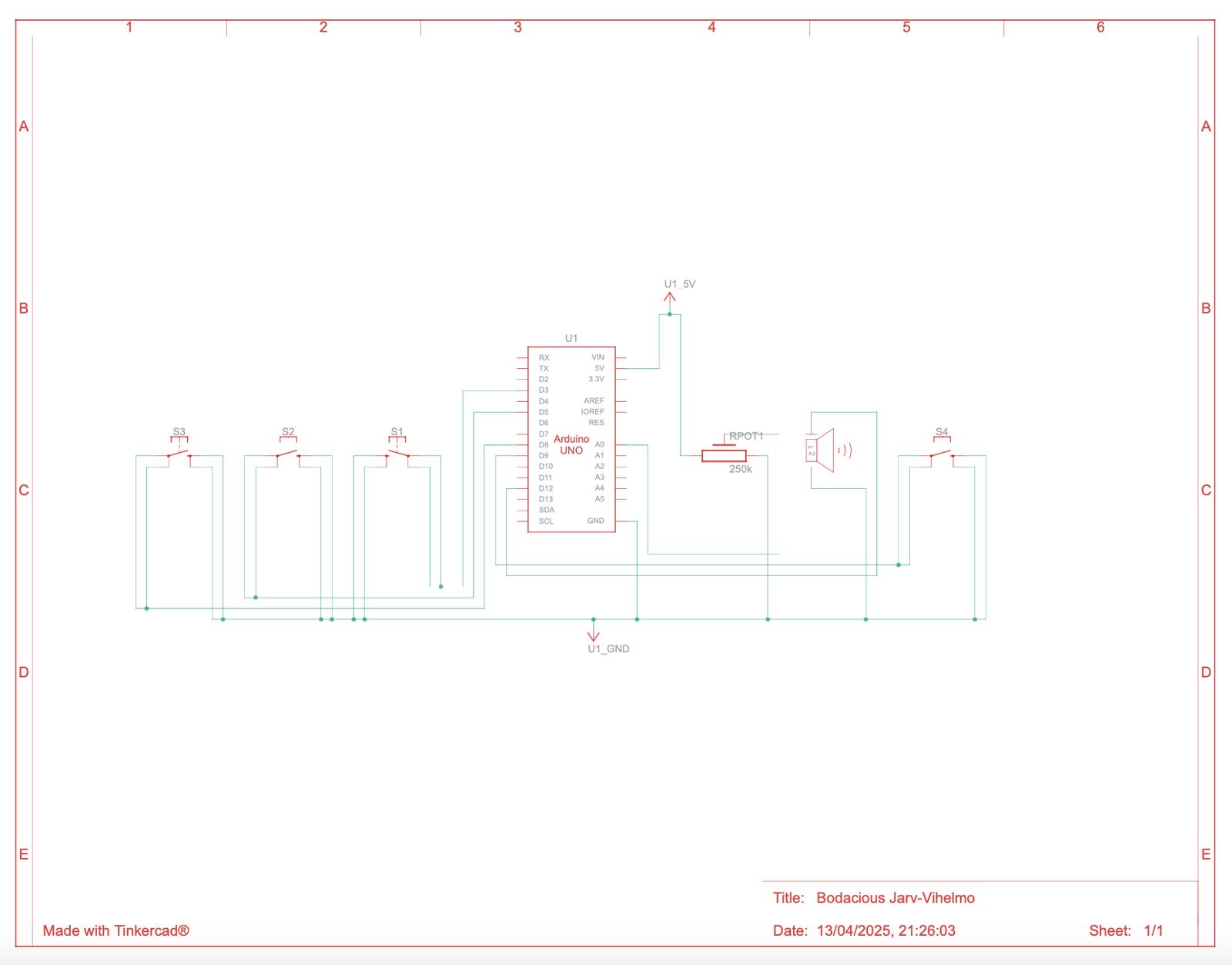
 For our group assignment, we built a simple digital musical instrument using an Arduino board. Our project was inspired by the children’s song Mary Had a Little Lamb, and we recreated the melody using four push buttons for four of the notes, C, D, E and G respectively. Each button acts as a digital sensor, triggering specific musical notes when pressed. The tones are played through a mini speaker connected to the Arduino, allowing the tune to be heard clearly. This created a very basic piano-style interface, with each button mapped to one of the notes in the song.
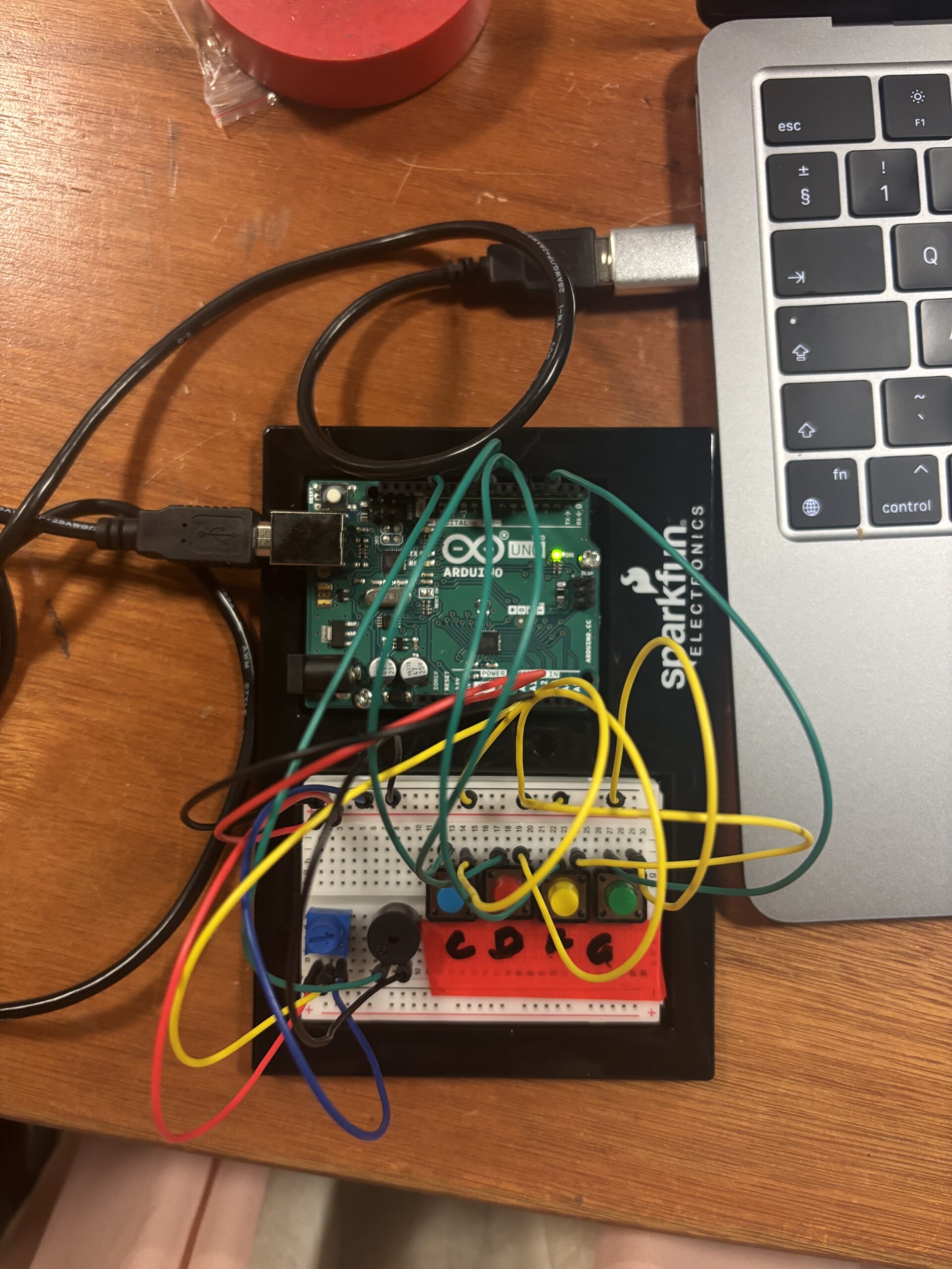
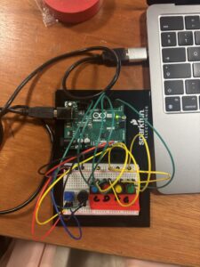 In addition to the buttons, we used a potentiometer as our analog sensor. This allowed us to control the frequency of the sound in real time. As the knob is turned, the pitch of the notes changes slightly, giving the player the ability to customize how the melody sounds. We mapped the frequency from 500-1000 Hz for this. It made the experience more interactive and demonstrated how analog inputs can add expressive control to digital systems. We also added some labels to the buttons so that it would be easier to play the music.
videos of testing :
(Sorry in advance, I’m not a singer, I just needed to show the song)
https://youtube.com/shorts/6OhDN7k7KAc?si=WBNaPPqKeTkQCIui
https://youtube.com/shorts/vH0wLT3W5Jk?si=3K7I34cpMZWwC9Ly
The code :
const int buttonPins[4] = {3, 5, 8, 9}; // buttons

//frequency for each button
int frequencies[4] = {262, 293, 330, 392}; //C, D , E , G notes
int potValue = 0; //to store potentiometer value

void setup() {
  //initialising buttons pins
  for (int i = 0; i < 4; i++) {
    pinMode(buttonPins[i], INPUT_PULLUP);
  }

  //for debugging
  Serial.begin(9600);

  //speaker pin for output
  pinMode(12, OUTPUT);
}

void loop() {
  //read the potentiometer value
  potValue = analogRead(A0);

  //map the potentiometer value to a frequency range 500-1000
  int adjustedFrequency = map(potValue, 0, 1023, 500, 1000);

  //for button and the corresponding note
  for (int i = 0; i < 4; i++) {
    if (digitalRead(buttonPins[i]) == LOW) { // Button is pressed (LOW because of INPUT_PULLUP)
      tone(12, frequencies[i] + adjustedFrequency);
      Serial.print("Button ");
      Serial.print(i+1);
      Serial.print(" pressed. Frequency: ");
      Serial.println(frequencies[i] + adjustedFrequency); //serial monitor
      delay(200);
    }
  }

  //to stop the tone when buttons arent being pressed
  if (digitalRead(buttonPins[0]) == HIGH && digitalRead(buttonPins[1]) == HIGH &&
      digitalRead(buttonPins[2]) == HIGH && digitalRead(buttonPins[3]) == HIGH) {
    noTone(12);
  }
}
PROBLEMS / IMPROVEMENTS :
As for problems or challenges, we didnt really have any specific problems with the circuit other than loose wires or something which was fixed after debugging and checking again. Something we understood from working together is that having two different perspectives helps a lot in solving problems and finding ideas.
We see a lot of potential for expanding this project in the future. One idea is to add a distance sensor to control volume based on hand proximity, making it even more dynamic. Another would be adding LEDs that light up with each button press to provide a visual cue for the notes being played. We’re also considering increasing the number of buttons to allow more complex songs, and possibly adding a recording function so users can capture and replay their melodies.
It was a fun and educational project that helped us better understand the relationship between hardware inputs and interactive sound output. It was exciting to bring a classic tune to life through code, sensors, and a mini speaker!