Hey everyone! 👋
This is it, my final project!
(wellll… actually, my backup project :(, but that’s a story for another time)
Description: It’s a glove that synthesizes music, controlled by your hand (specifically, the curling of the fingers), with feedback being shown on both the glove itself (through the neopixels, aka addressable LED strips), and also on the screen (with a p5 interface).
So, how does it work?
As stated previously, the music is controlled by the curl of the fingers. This is detected with flex sensors attached on the glove, which is then fed into the Arduino, mapped from an auto-calibrated range to the control values, which then modify the sound in different ways (the 4 fingers control the base frequency (can be interpreted as pitch), tempo (speed), mix ratio, and multiplier, respectively). These values are also mapped and shown on the neopixels attached on top of the flex sensors, providing immediate visual feedback (and ngl, they also just look cool, but that shouldn’t be overdone). For example, the neopixel for the speed, actually changes its blink rate based on the speed. The auto-calibrated range values are also mapped into the range 0-1000 and sent to the p5 sketch, allowing it to alter the height of the bars representing each control, and also modify the center circle based on the values.
Arduino code:
// Configuring Mozzi's options
#include
#define MOZZI_ANALOG_READ_RESOLUTION 10 // Not strictly necessary, as Mozzi will automatically use the default resolution of the hardware (eg. 10 for the Arduino Uno), but they recommend setting it (either here globally, or on each call)

#include
#include  // oscillator
#include <tables/cos2048_int8.h> // table for Oscils to play
#include

#include  // For the neopixels


// Flex sensor stuff

// Define flex sensor pins (these have to be analog)
const int FREQ_SENSOR_PIN = A0;
const int SPEED_SENSOR_PIN = A1;
const int MOD_SENSOR_PIN = A2;
const int RATIO_SENSOR_PIN = A3;

// Smoothening for each pin
Smooth smoothFreq(0.8f);
Smooth smoothSpeed(0.8f);
Smooth smoothSpeedLED(0.8f);
Smooth smoothMod(0.8f);
Smooth smoothRatio(0.8f);

// Input ranges for flex sensors (will be calibrated)
unsigned int freqInputMin = 1000; // Just FYI, the flex sensors in our setup roughly output in the range of ~ 200 - 650
unsigned int freqInputMax = 0;
unsigned int modInputMin = 1000;
unsigned int modInputMax = 0;
unsigned int speedInputMin = 1000;
unsigned int speedInputMax = 0;
unsigned int ratioInputMin = 1000;
unsigned int ratioInputMax = 0;


// Neopixel (addressable LED strip) stuff

// Define neopixel pins
const int FREQ_NEOPIXEL_PIN = 2;
const int SPEED_NEOPIXEL_PIN = 3;
const int MOD_NEOPIXEL_PIN = 4;
const int RATIO_NEOPIXEL_PIN = 5;

// Number of LEDs in each strip
const int NEOPIXEL_NUM_LEDS = 11;

// Define the array of leds
CRGB freqLEDs[NEOPIXEL_NUM_LEDS];
CRGB modLEDs[NEOPIXEL_NUM_LEDS];
CRGB speedLEDs[NEOPIXEL_NUM_LEDS];
CRGB ratioLEDs[NEOPIXEL_NUM_LEDS];


// Sound stuff

// desired carrier frequency max and min
const int MIN_CARRIER_FREQ = 22;
const int MAX_CARRIER_FREQ = 440;

// desired intensity max and min, inverted for reverse dynamics
const int MIN_INTENSITY = 10;
const int MAX_INTENSITY = 1000;

// desired modulation ratio max and min
const int MIN_MOD_RATIO = 5;
const int MAX_MOD_RATIO = 2;

// desired mod speed max and min, note they're inverted for reverse dynamics
const int MIN_MOD_SPEED = 10000;
const int MAX_MOD_SPEED = 1;

Oscil<COS2048_NUM_CELLS, MOZZI_AUDIO_RATE> aCarrier(COS2048_DATA);
Oscil<COS2048_NUM_CELLS, MOZZI_CONTROL_RATE> kIntensityMod(COS2048_DATA);
Oscil<COS2048_NUM_CELLS, MOZZI_AUDIO_RATE> aModulator(COS2048_DATA);

int mod_ratio; // harmonics
long fm_intensity; // carries control info from updateControl() to updateAudio()

// smoothing for intensity to remove clicks on transitions
float smoothness = 0.95f;
Smooth aSmoothIntensity(smoothness);

// To keep track of last time Serial data was sent, to only send it every x millis
int lastTimeSerialSent = 0;


void setup(){
  Serial.begin(9600); // For communicating with p5

  // Set the flex sensor pins
  pinMode( FREQ_SENSOR_PIN, INPUT_PULLUP);
  pinMode(  MOD_SENSOR_PIN, INPUT_PULLUP);
  pinMode(SPEED_SENSOR_PIN, INPUT_PULLUP);
  pinMode(RATIO_SENSOR_PIN, INPUT_PULLUP);

  // Setup the neopixels
	FastLED.addLeds<NEOPIXEL, FREQ_NEOPIXEL_PIN>(freqLEDs, NEOPIXEL_NUM_LEDS);
	FastLED.addLeds<NEOPIXEL, MOD_NEOPIXEL_PIN>(modLEDs, NEOPIXEL_NUM_LEDS);
	FastLED.addLeds<NEOPIXEL, SPEED_NEOPIXEL_PIN>(speedLEDs, NEOPIXEL_NUM_LEDS);
	FastLED.addLeds<NEOPIXEL, RATIO_NEOPIXEL_PIN>(ratioLEDs, NEOPIXEL_NUM_LEDS);
	FastLED.setBrightness(32); // 0 - 255

  // Feed/prime/initialise the smoothing function to get a stable output from the first read (to ensure the calibration isn't messed up). A value of 1630 was chosen by trial and error (divide and conquer), and seems to work best (at least for our setup)
  smoothFreq.next(1630);
  smoothMod.next(1630);
  smoothSpeed.next(1630);
  smoothRatio.next(1630);

  startMozzi();

  // Start the serial handshake
  while (Serial.available() <= 0) {
    digitalWrite(LED_BUILTIN, HIGH); // on/blink while waiting for serial data
    Serial.println("0"); // send a starting message
    delay(250);
    digitalWrite(LED_BUILTIN, LOW);
    delay(250);
  }
}


// Basically our actual traditional loop in Mozzi (but still needs to kept reasonably lean and fast)
void updateControl(){

  // Read the smoothened freq
  int freqValue = smoothFreq.next(mozziAnalogRead(FREQ_SENSOR_PIN - 14)); // value is 0-1023, -14 since mozzi just takes a number (eg. 0 instead of A0), and the analog ones are 14 onwards

  // Calibrate the mapping if needed
  if (freqValue < freqInputMin) freqInputMin = freqInputMin * 0.5 + freqValue * 0.5; if (freqValue > freqInputMax) freqInputMax = freqInputMax * 0.5 + freqValue * 0.5;

  // Map the input to the carrier frequency
  int carrier_freq = map(freqValue, freqInputMin, freqInputMax, MIN_CARRIER_FREQ, MAX_CARRIER_FREQ);


  // Read the smoothened ratio
  int ratioValue = smoothRatio.next(mozziAnalogRead(RATIO_SENSOR_PIN - 14));

  // Calibrate the mapping if needed
  if (ratioValue < ratioInputMin) ratioInputMin = ratioInputMin * 0.5 + ratioValue * 0.5; if (ratioValue > ratioInputMax) ratioInputMax = ratioInputMax * 0.5 + ratioValue * 0.5;

  // Map the input to the ratio
  mod_ratio = map(ratioValue, ratioInputMin, ratioInputMax, MIN_MOD_RATIO, MAX_MOD_RATIO);


  // calculate the modulation frequency to stay in ratio
  int mod_freq = carrier_freq * mod_ratio;

  // set the FM oscillator frequencies to the calculated values
  aCarrier.setFreq(carrier_freq);
  aModulator.setFreq(mod_freq);


  // Read the smoothened mod
  int modValue = smoothMod.next(mozziAnalogRead(MOD_SENSOR_PIN - 14));

  // Calibrate the mapping if needed
  if (modValue < modInputMin) modInputMin = modInputMin * 0.5 + modValue * 0.5; if (modValue > modInputMax) modInputMax = modInputMax * 0.5 + modValue * 0.5;

  // Calculate the fm_intensity
  fm_intensity = ((long)modValue * (kIntensityMod.next()+128))>>8;


  // Read the smoothened speed
  int speedValue = smoothSpeed.next(mozziAnalogRead(SPEED_SENSOR_PIN - 14));

  // Calibrate the mapping if needed
  if (speedValue < speedInputMin) speedInputMin = speedInputMin * 0.5 + speedValue * 0.5; if (speedValue > speedInputMax) speedInputMax = speedInputMax * 0.5 + speedValue * 0.5;

  // use a float here for low frequencies
  float mod_speed = (float)map(speedValue, speedInputMin, speedInputMax, MIN_MOD_SPEED, MAX_MOD_SPEED) / 1000;
  kIntensityMod.setFreq(mod_speed);


  // Set the leds

  FastLED.clear(); // Resets them

  // The frequency controls how many of the LEDs are light up (in a rainbow colour)
  int freqLEDAmount = map(freqValue, freqInputMin, freqInputMax, 0, NEOPIXEL_NUM_LEDS);
  fill_rainbow(&freqLEDs[NEOPIXEL_NUM_LEDS - freqLEDAmount], freqLEDAmount, CRGB::White, 25); // &...LEDs[i] to start lighting from there, allowing us to light them in reverse

  // The speed controls the blinking rate of its LEDs (between 1/2 to 3 seconds per blink cycle)
  int speedLEDBlinkRate = smoothSpeedLED.next(map(speedValue, speedInputMin, speedInputMax, 2000, 500));
  if (millis() % speedLEDBlinkRate < speedLEDBlinkRate/2)
    fill_rainbow(speedLEDs, NEOPIXEL_NUM_LEDS, CRGB::White, 25);

  // For the mod, show a meter (blue - deep pink) showing the mix level of the 2 sounds
  int modLEDAmount = map(modValue, modInputMin, modInputMax, 0, NEOPIXEL_NUM_LEDS);
  fill_solid(modLEDs, NEOPIXEL_NUM_LEDS, CRGB::Blue);
  fill_solid(&modLEDs[NEOPIXEL_NUM_LEDS - modLEDAmount], modLEDAmount, CRGB::DeepPink);

  // The ratio controls the hue of its LEDs
  // int ratioLEDHue = map(ratioValue, ratioInputMin, ratioInputMax, 0, 360);
  // fill_solid(ratioLEDs, NEOPIXEL_NUM_LEDS, CHSV(ratioLEDHue, 100, 50));
  // We could also blend between 2 colours based on the ratio, pick the one you prefer
  fract8 ratioLEDFraction = map(ratioValue, ratioInputMin, ratioInputMax, 0, 255);
  // fill_solid(ratioLEDs, NEOPIXEL_NUM_LEDS, blend(CRGB::Blue, CRGB::DeepPink, ratioLEDFraction));
  fill_solid(ratioLEDs, NEOPIXEL_NUM_LEDS, blend(CRGB::Blue, CRGB::Red, ratioLEDFraction));

  FastLED.show(); // Shows them


  // Communicate with p5

  if (Serial.available() && Serial.read() == '\n') { // Send the data once a newline character is received, indicating the end of a message/handshake
      Serial.print(map(freqValue, freqInputMin, freqInputMax, 0, 1000));
      Serial.print(',');
      Serial.print(map(speedValue, speedInputMin, speedInputMax, 0, 1000));
      Serial.print(',');
      Serial.print(map(modValue, modInputMin, modInputMax, 0, 1000));
      Serial.print(',');
      Serial.print(map(ratioValue, ratioInputMin, ratioInputMax, 0, 1000));
      Serial.print(',');
      Serial.println(speedLEDBlinkRate);
    }
  }
}


// Mozzi's function for getting the sound. Must be as light and quick as possible to ensure the sound buffer is adequently filled
AudioOutput updateAudio() {
  long modulation = aSmoothIntensity.next(fm_intensity) * aModulator.next();
  return MonoOutput::from8Bit(aCarrier.phMod(modulation)); // phMod does the FM
}


// Since we're using Mozzi, we just call its hook
void loop() {
  audioHook();
}
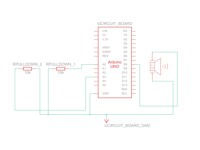
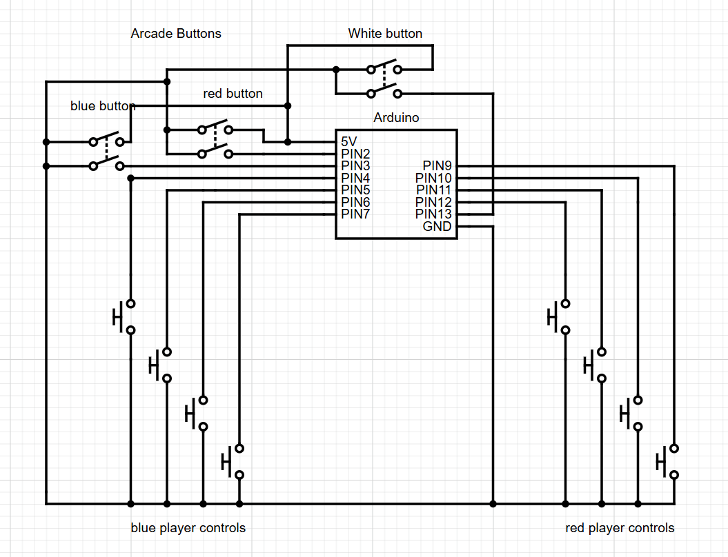
Schematic:
p5 sketch (and code):
Description of communication between Arduino and p5:
They communicate using a wired serial connection, with the Arduino initiating the handshake. Once p5 acknowledges it, it sends back a newline character, causing the Arduino to send over the normalised values of the flex sensors, as well as the speed neopixel’s blinkrate, and then a newline character back (delimiting the end of the message). Each part waits until the newline to send their data (in the case of p5, just an acknowledgement, while in the case of the Arduino, the sensor and 1 computed value).
While I’m not incredibly happy for this, and do wish I could improve things a lot, I’m still pretty glad with how some things turned out. The glove input and the glove itself proved to be quite liked, with many people commenting about the unique control scheme. I also feel the p5 sketch provided another option to view data, resulting in a quicker understanding of the mapping between the amount the fingers are curled and the value it outputs.
However (for future reference), I do wish I could provide greater variety in the synthesizing options (eg. I thought of a button that cycles through different modes, with one mode for example controlling a set of instruments), improve the design & sturdiness of the glove (one of the wires actually disconnected! But luckily it was near the end of the show), and also polish it a bit more.