Fortune Teller
Concept
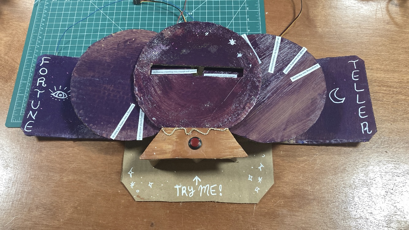
For my final project, I was initially inspired to create a fortune teller by my favorite book series, The Raven Cycle, in which the main character is from a family of psychics. The interface went through many iterations to become what it is now. First, I thought it would be a telephone interface, in which the user would “call” different numbers to get different predictions. Then, I thought I would make a “Magic 8 Ball” type object with a digital screen to display the various predictions. Finally, I settled on an entirely non digital display because I wanted the “whimsical” feel of hand painted cardboard. A conversation with Professor Shiloh further encouraged me to go with this option, as when I shared my idea for having “wheels” that would rotate to display the predictions, he suggested that the predictions could be split up into sentence beginnings and endings, which would allow for many more combinations.
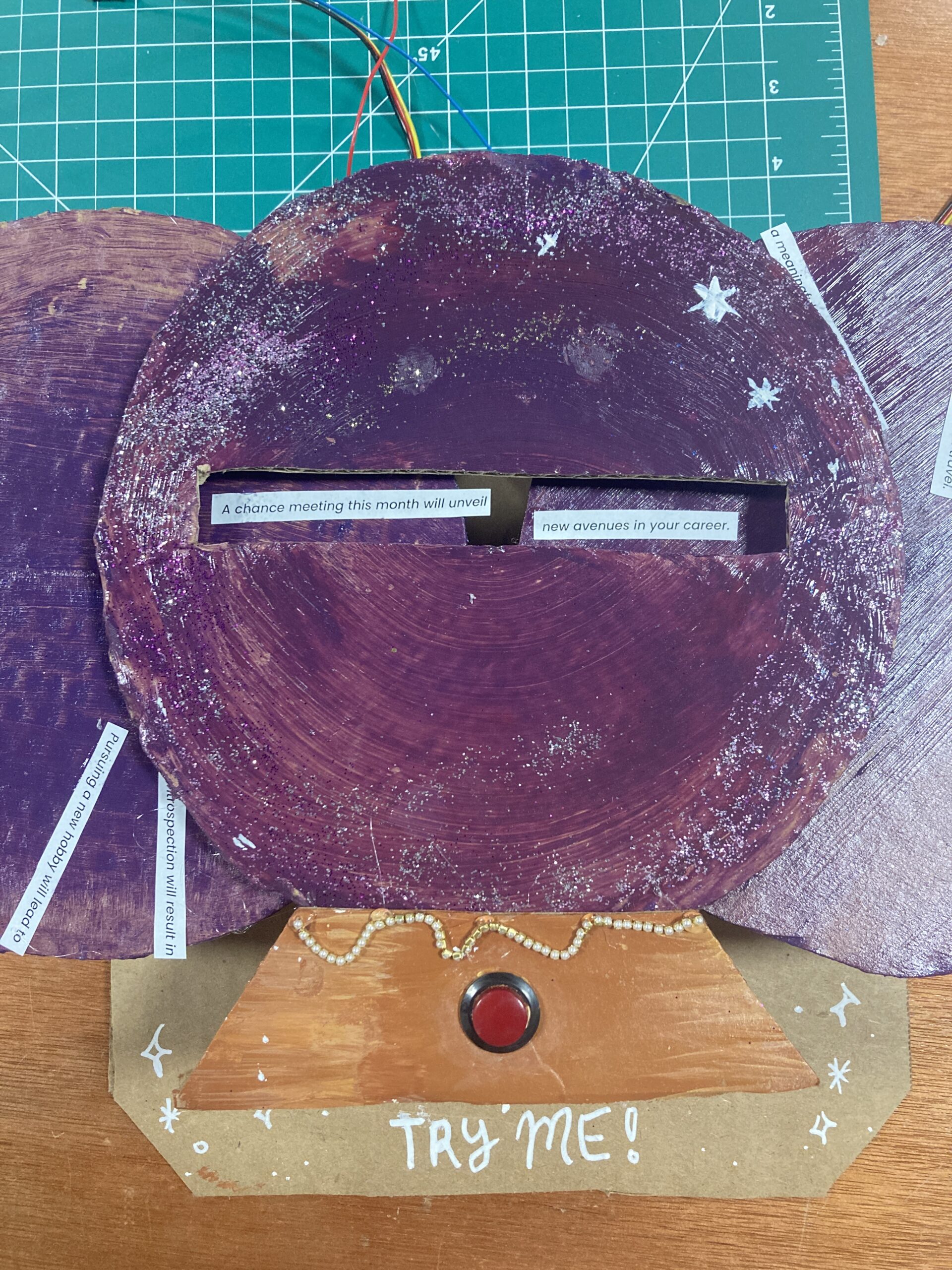
Thus, my final design consisted of two wheels attached to servo motors. When the user presses a button, the servos would choose two random angles to rotate to from an array of predetermined angles. The angle of rotation would then determine which sentence beginning and ending showed through the display slot. With the help of Chat GPT, I generated 6 sentence beginnings and endings that can all combine together to form 36 coherent predictions regarding relationships, the future, and self improvement.
Interaction Design & User Testing
The interaction between the user and the fortune teller is quite straightforward — the user pushes a button and receives a fortune. During my user-testing, I was pleasantly surprised to see that people enjoyed receiving different fortunes, and would press the button many times to see new fortunes. They also related the fortunes to their own lives, which reminded me of why humans enjoy things like astrology and fortune cookies. Even if we do not actually believe in their accuracy, it is still fun to apply these vague predictions to our current situations, and I think this is what motivated people to have a sustained interaction with my project. Furthermore, I think the fact that you can see the wheels spinning lends intrigue to the interaction. I think the simplicity of the interaction turned out to be its strength, as people quickly figured out what to do and did not need any explanation from me.
Arduino Code:
My code consisted of three main mechanisms, one for detecting button state, one for choosing a random angle for each of the servo motors, and one for moving the servos smoothly to the chosen angle. One of the most difficult part of this assignment for me was understanding the logic behind each of these mechanisms, as I had never used state detection in any of my previous projects.
1. Button State: If the current button state is different than the previous button state AND it is high, meaning that the user has pressed the button, then the subsequent actions of choosing a random angle and moving the servos will take place.
2. Angle Selection: A random angle is chosen from an array of angles. The code will keep searching for a new angle until it is different from the previous angle, thus preventing an occurrence of the same 2 angles in a row. This is repeated for both servos.
3. Moving Servo: The for loop is for detecting if the previous angle is larger than or smaller than the current angle, and for smoothly incrementing the servo degree by degreee (either adding 1 or subtracting 1) to reach that angle. I did this after I found that not using the for loop resulted in extremely jerky movements.
Full code:
// Include Servo library
#include <Servo.h>

// Initialize servo object
Servo servoL;  // left servo
Servo servoR;  // right servo

// Variables for pins
const int servoPinL = 11;
const int servoPinR = 9;
const int buttonPin = 7;

// Set last button state to LOW
int lastButtonState = HIGH;

// Set last angle index to 0, aka the first angle in the array
int lastAngleIndexL = 0;
int newAngleIndexL;

int lastAngleIndexR = 0;
int newAngleIndexR;


// Array of angles for servo motor to choose from
int angles[] = { 10, 35, 63, 94, 123, 159 };

// 10, 35, 63, 94, 123, 159
// Calculate size of angles[] array, needed for random()
int sizeAngles = sizeof(angles) / sizeof(angles[0]);

void setup() {
  Serial.begin(9600);

  servoL.attach(servoPinL);
  servoR.attach(servoPinR);
  pinMode(buttonPin, INPUT_PULLUP);

  // Initialize servos at the first angle in angles[] array
  servoL.write(angles[lastAngleIndexL]);
  servoR.write(angles[lastAngleIndexR]);

  // Initialize random number generator
  randomSeed(analogRead(0));
}

void loop() {
  int currentButtonState = digitalRead(buttonPin);
  delay(15);

  if (lastButtonState != currentButtonState) {
    if (currentButtonState == LOW) {

      //// LEFT SERVO ////
      do {
        // generate a new random angle index
        newAngleIndexL = random(sizeAngles);
        // keep looking for a new random angle until it is different from the last
      } while (newAngleIndexL == lastAngleIndexL);

      // decide which way to turn
      if (angles[lastAngleIndexL] < angles[newAngleIndexL]) {
        for (int pos = angles[lastAngleIndexL]; pos < angles[newAngleIndexL]; pos++)
          servoL.write(pos);
        delay(100);
      } else {
        // go in other direction, pos--
        for (int pos = angles[lastAngleIndexL]; pos > angles[newAngleIndexL]; pos--)
          servoL.write(pos);
        delay(100);
      }

      Serial.print("Left Servo Angle: ");
      Serial.println(angles[newAngleIndexL]);

      //update the lastAngleIndex to show that we are now here
      lastAngleIndexL = newAngleIndexL;

      //// RIGHT SERVO ////
      do {
        // generate a new random angle index
        newAngleIndexR = random(sizeAngles);
        // keep looking for a new random angle until it is different from the last
      } while (newAngleIndexR == lastAngleIndexR);

      // decide which way to turn
      if (angles[lastAngleIndexR] < angles[newAngleIndexR]) {
        for (int pos = angles[lastAngleIndexR]; pos < angles[newAngleIndexR]; pos++)
          servoR.write(pos);
        delay(100);
      } else {
        // go in other direction, pos--
        for (int pos = angles[lastAngleIndexR]; pos > angles[newAngleIndexR]; pos--)
          servoR.write(pos);
        delay(100);
      }

      Serial.print("Right Servo Angle: ");
      Serial.println(angles[newAngleIndexR]);

      //update the lastAngleIndex to show that we are now here
      lastAngleIndexR = newAngleIndexR;
    }

    // update the button state
    lastButtonState = currentButtonState;
  }
}
I did not have any p5.js code or serial communication as I was granted an exception to do my whole project in Arduino.
Parts I am proud of:
The most frustrating part of my project was the interaction between the Arduino code and the physical cardboard construction, especially since the angles of rotation were integral to the whole concept working. First, I tried to draw the angles on the cardboard and try to write the code so that the angles I determined would cause the predictions to show through. This proved unsatisfactory and I had to reduce the number of wedges from 10 to 6, and eventually I wrote another program using the Knob servo example so that I could decide the angles based on which area showed through the display slot as I turned the knob, instead of deciding the angles first.
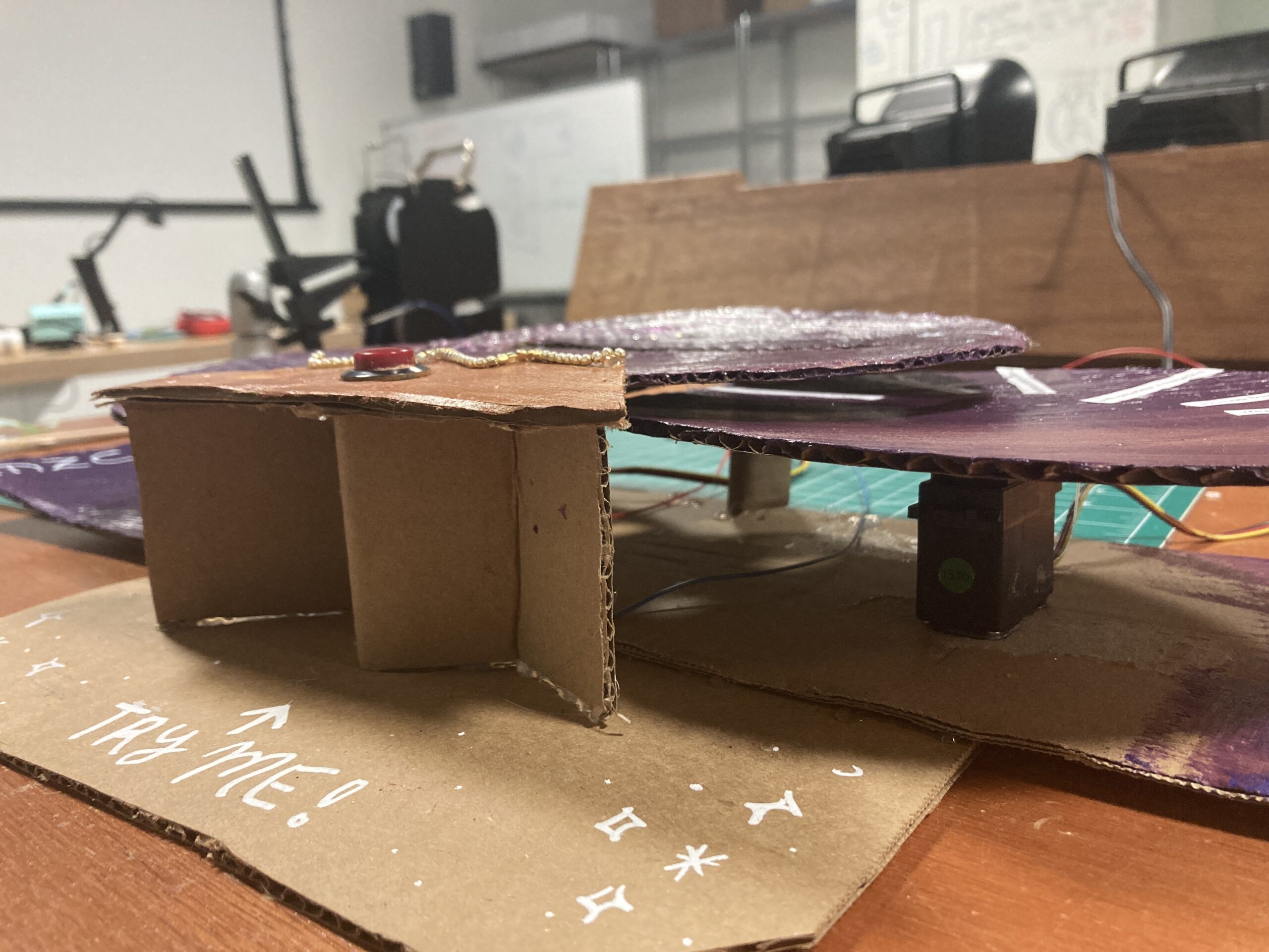
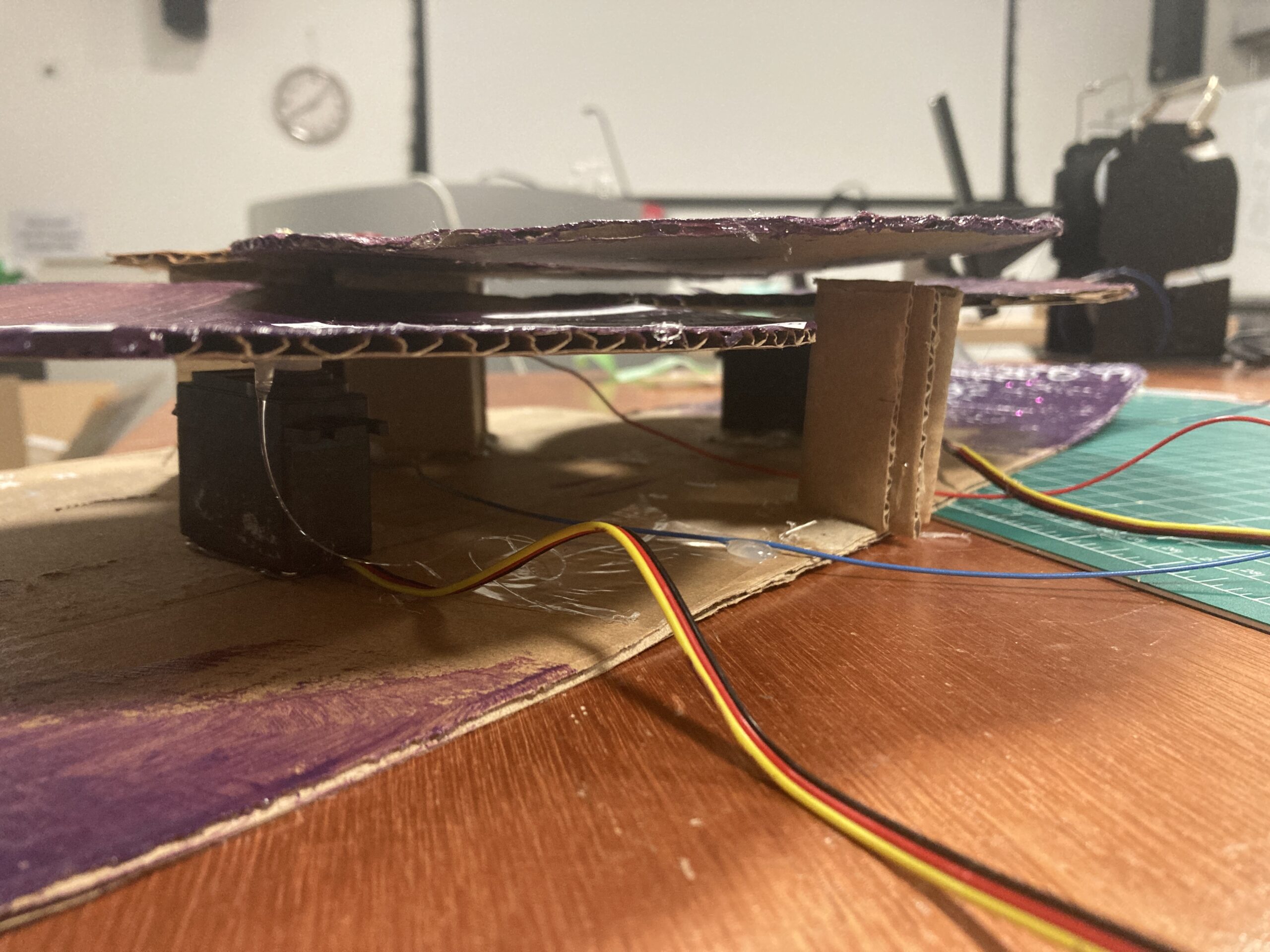
Additionally, the servo motors were very jittery and unstable at times, which made testing my concept an arduous process, as I had to continually disassemble both the cardboard slot and the motors to achieve an optimal setup. Thus, I am most proud of overcoming all these difficulties along the road, and making a (relatively) stable physical product with a form that serves its function well. I am also happy with the cardboard construction techniques I used, such as supporting my structure with triangle wedges:
Future Improvement:
If I were to do this project again, I would precisely measure and calculate everything before construction so I could have space for more predictions like I originally planned. Also, currently the wheels will turn erratically or the servo motors will vibrate at random times, and I still do not know why. An area for future improvement would be to eradicate these bugs, although they could be interpreted as divine psychic interference :).
Resource: