For this assignment, the task was to create an unusual switch (that opens and closes a circuit) using Arduino.
Inspiration
Anyone who knows me knows how much I love plushies! When I started brainstorming project ideas, I wanted to create something cute that included two of my own plushies—Beany the bear and Snowball the penguin. I was also inspired by the movie Inside Out, especially how the character Joy is represented with a warm yellow glow. This gave me the idea to create a scene where one of my plushies says “hi” to the other, sparking a little moment of joy between them.
Concept
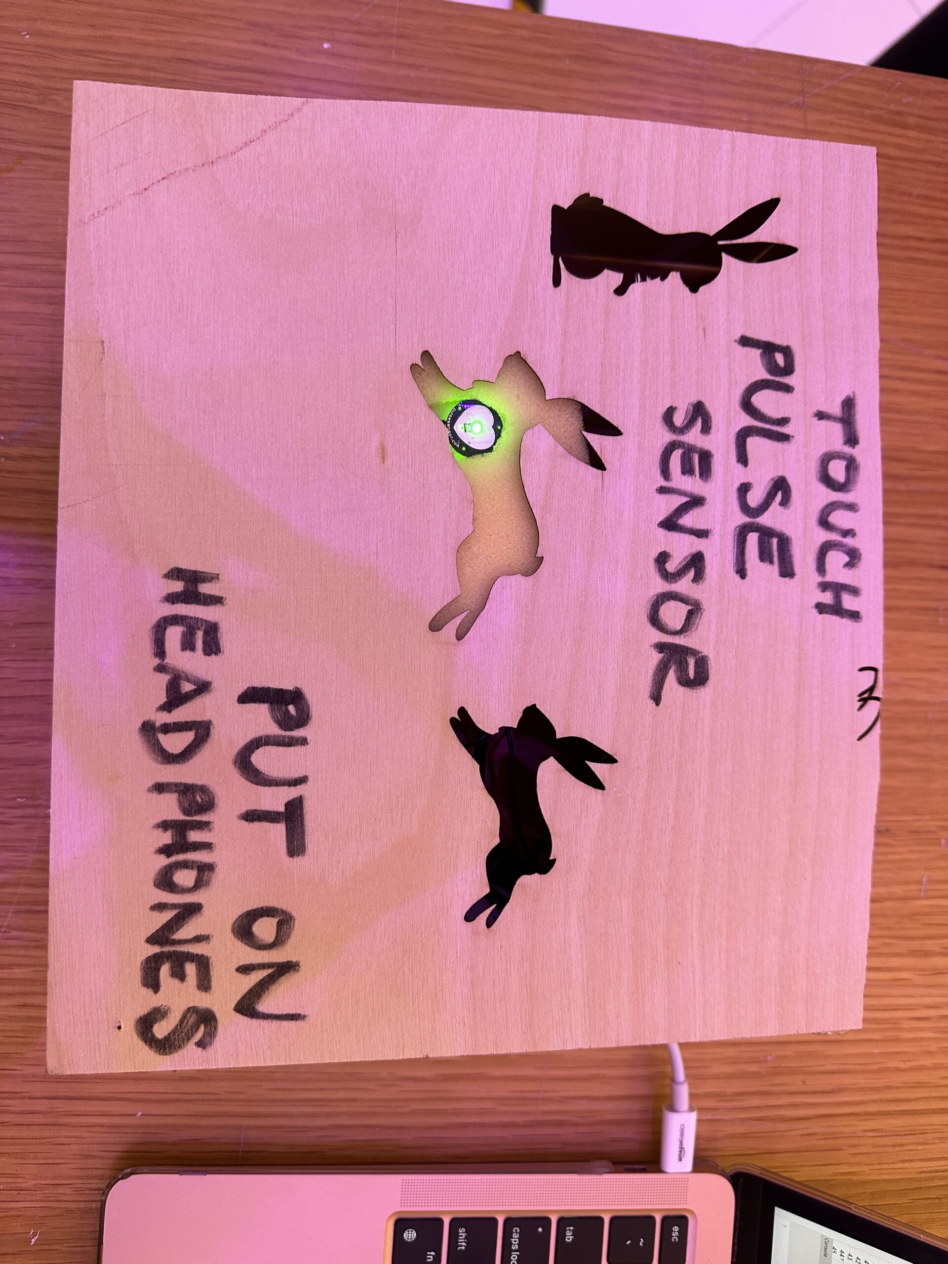
The main concept behind my project is to create a glowing yellow heart made of LEDs that lights up when Snowball places his hand on Beany’s shoulder, representing a moment of joy. Using Arduino, I wanted to wire a small circuit with conductive foil attached to each plushie. When the two plushies make contact, the conductive foils complete the circuit, sending a signal through the Arduino to illuminate the LED heart.
Implementation
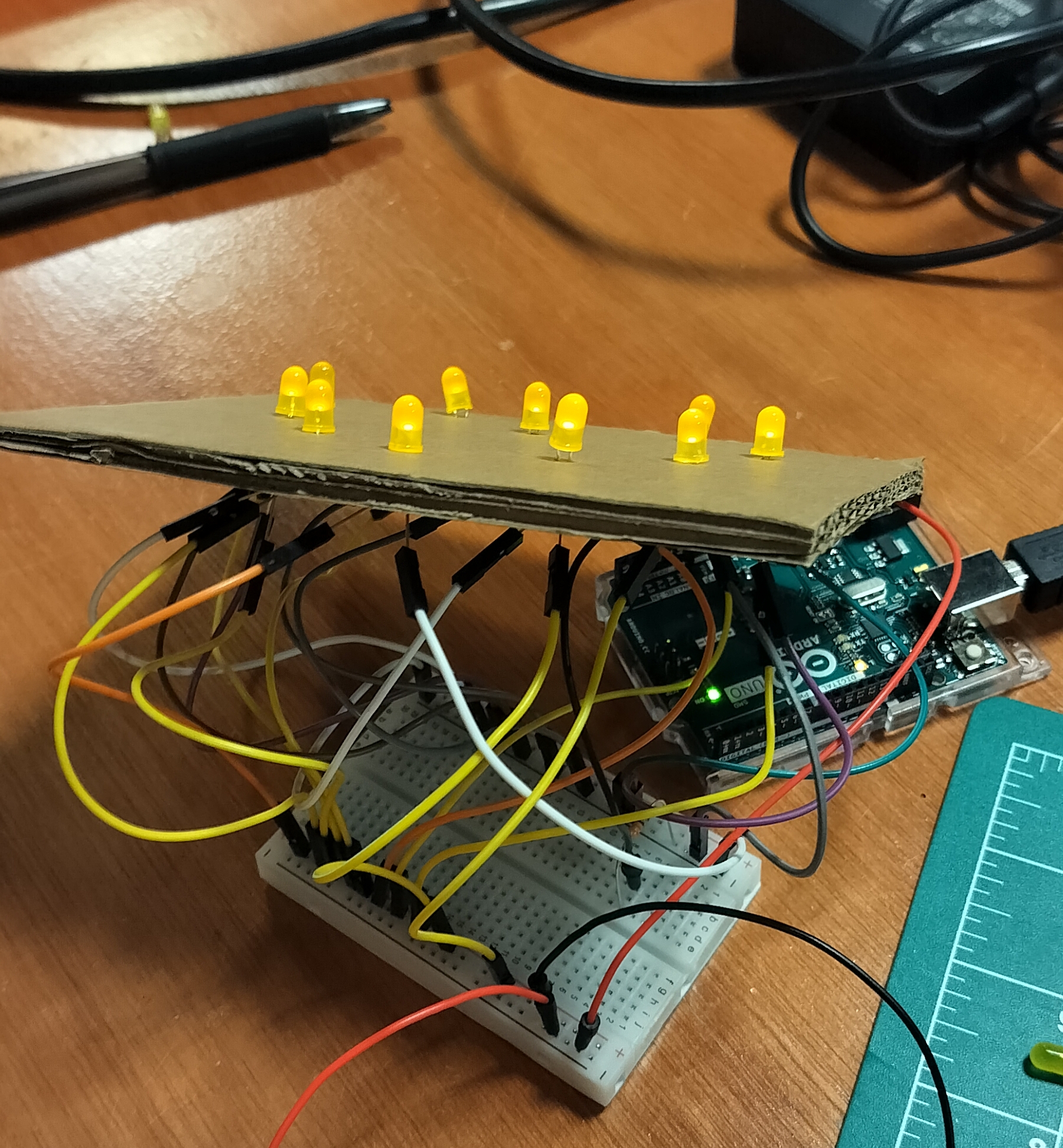
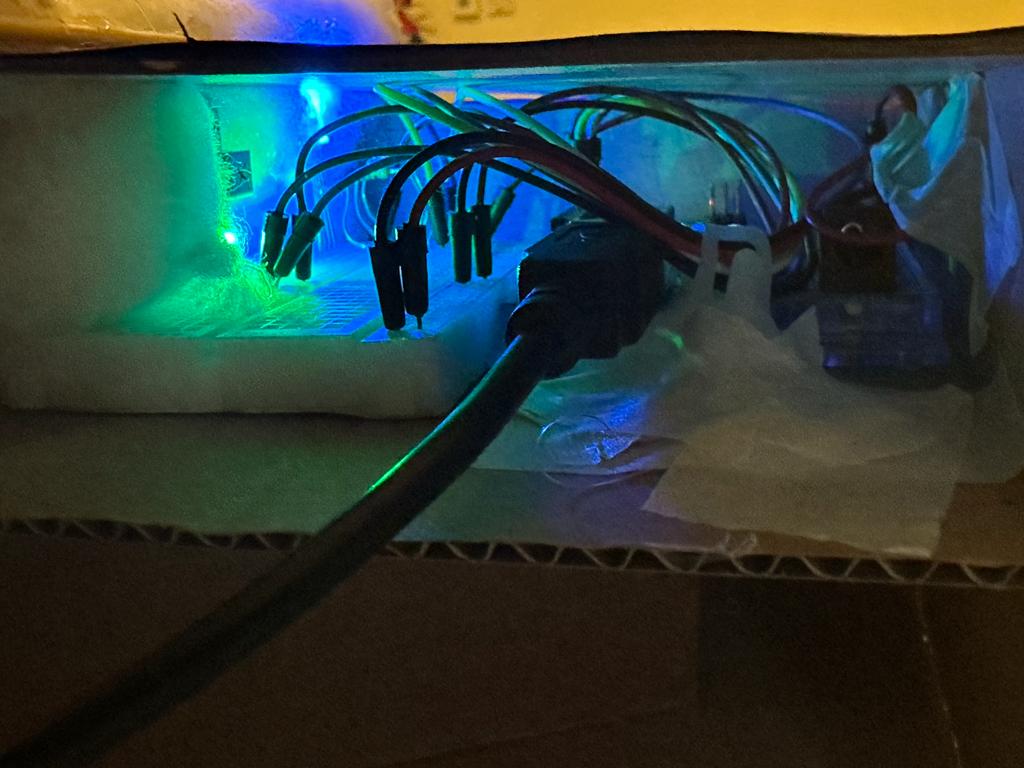
To bring my idea to life, I started by cutting a piece of cardboard and arranging spots for the LEDs in the shape of a heart. After placing the LEDs, I wired them in parallel, connecting their negative terminals to the ground on the Arduino board. I connected the positive terminals of the LEDs to a 330-ohm resistor, which was then connected to one piece of conductive foil on one of the plushies. The other piece of conductive foil, attached to the second plushie, was connected to the Arduino’s 5V terminal. This setup meant that when the two plushies “touched,” the circuit would complete through the resistor, causing the LED heart to glow.
Here’s a picture of just the LED heart and its wiring:
When I filmed the final product, I got a (teeny-tiny) bit carried away and ended up creating a short, movie-like video with the Inside Out theme song as background music. It really added to the emotion I wanted to capture in this project :))
Reflections and Further Improvements
Overall, I’m pretty happy with how this project turned out! The wiring was a bit challenging due to the number of LEDs I used, which sometimes caused the wires to get tangled, but overall, the process went smoothly. As mentioned previously, I also invested some time in filming the final product to give it a more story-like feel.
For future improvements, I might consider adding some sort of sound element that plays whenever the circuit is completed. It would also be nice to make the setup more compact or even fully portable. Lastly, I’d love to explore adding different light patterns or colors to show various emotions, which would create even more expressive interactions between the plushies.
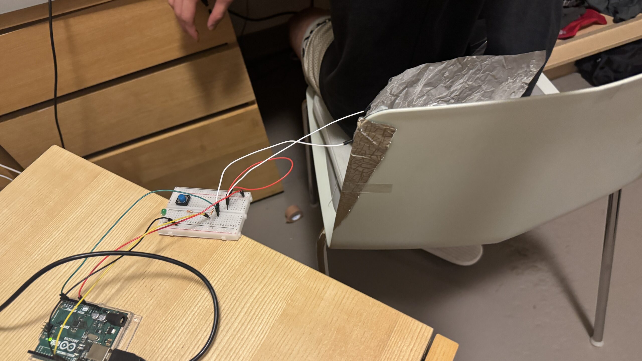
This idea is distantly inspired by how cars warn you when your seatbelt is not attached. I was inspired by the concept of leds lighting up or not lighting up based on humans interactions with chairs.
How I proceeded was adapting the code and circuit from the in-class example to fit my needs. I replaced the switch with 2 wires attached to 2 pieces of tin-foil, one attached to my chair, and one attached to my shirt.
The LED lights up when i lean back on my chair, and turns off when I’m not leaning back on my chair.
The code that controls the output pretty much is the same as the in-class exercise, where when the circuit is connected, the led lights up, and when it is closed, the led dims.
int buttonState = digitalRead(A2);

if (buttonState == HIGH) {

digitalWrite(13, HIGH);

} else {

digitalWrite(13, LOW);
Improvements:
Currently, I’m using 2 pieces of tin foil loosely attached to my shirt and to my chair, for the future, something like this could be implemented with a pressure sensor of sorts, where it can determine how much pressure I am applying on the chair, which could affect the brightness of the LED. This would not only be better in terms of not needing conductive material but it also increases functionality. Continue reading “Week 8 Unusual Switch”
Norman,“Emotion & Design: Attractive things work better”
My personal view of design when it comes to applications/ websites goes deep into the particular balance of design and practicality and I think the author does an amazing job with explaining that concept. I believe the whole conceot of desin is completely objective where it depends on a person’s preference. One recent debate I have seen spread throughout social media is whether makeup brands fit their brand’s aesthetic or not on their website. The main brand that is talked about is Ariana Grande’s R.E.M. Beauty where many people argue that the website lacks aesthetic, whereas it is compared to other beauty brands like Apothecary 87 and KKW Beauty. This just shows the importance of design and how its existence is crucial.
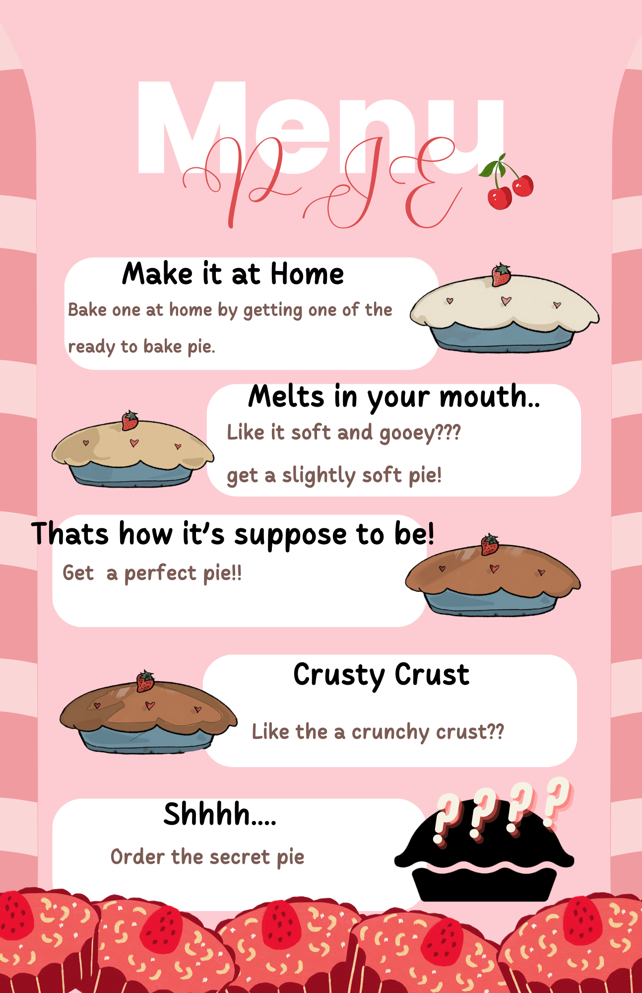
I love baking, and I enjoy baking games. For my final project I decided to make a pie shop… Throughout my journey in Intro to IM, I made sure to always add a piece of me in every assignment and project. This final one is especially dear to me because I was able to finalize it after hard work. As well as being able to add my art in it (background and pie images). I think it goes well together and I’m proud of it.
function submitAnswer() {
  // Define the expected ranges for each statement
  const rawRange = [0, 200];
  const undercookedRange = [201, 400];
  const perfectRange = [401, 600];
  const overcookedRange = [601, 800];
  const burntRange = [801, 1023];

  let expectedRange;

  // Determine the expected range based on the current sentence
  switch (currentSentence) {
    case "I would like a raw pie to bake at home.":
      expectedRange = rawRange;
      break;
    case "I like my pie extremely soft.":
      expectedRange = undercookedRange;
      break;
    case "I want a perfect pie!":
      expectedRange = perfectRange;
      break;
    case "Crispy around the edges!!":
      expectedRange = overcookedRange;
      break;
    case "BURNT IT >:D":
      expectedRange = burntRange;
      break;
  }

  // Check if the current image range matches the expected range
  if (x >= expectedRange[0] && x <= expectedRange[1]) {
    // Increment the score for a correct match
    score++;

  ding.play();
-Different screen pages:
if (gameState === "start") {
  drawStartScreen();
} else if (gameState === "playing") {
  displayFoodImage();
  displayTimer();
  textSize(24);
  fill(255);
  text("Score: " + score, width - 100, 30);
} else if (gameState === "end") {
  // Display results in the end screen
  textSize(210);
  fill(255);
  text("Your Score: " + score, width / 2, height / 2);
  playAgainButton.show(); // Show the button on the end screen
}
else {
  // Draw other game elements here
  playAgainButton.hide(); // Hide the button if not in the end state
}
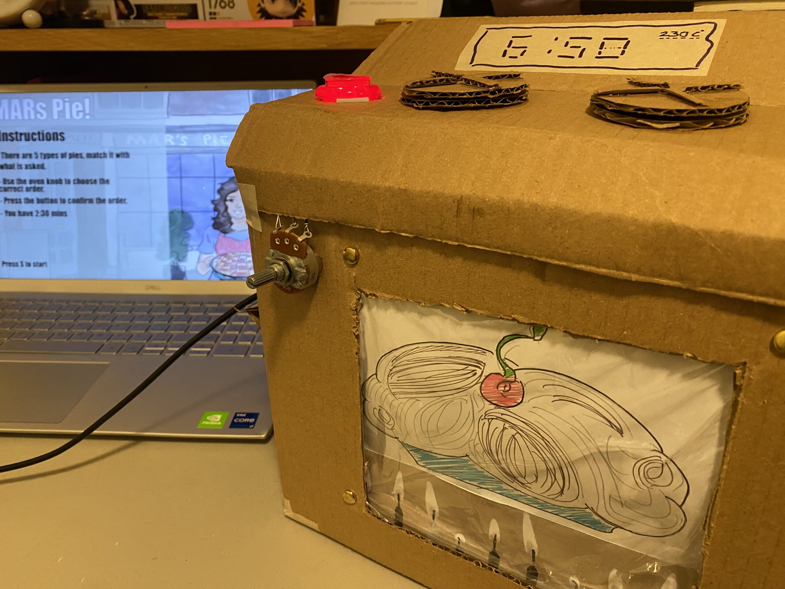
main COMPONENTS:
-LED Button
-Potentiometer
OVEN PROTOTYPE AND SCHEMATICS:
USER TESTING:
CHALLENGES:
Many challenges were faced with the coding part.
Button wasn’t working to confirm answers and also change the requests of the order.
Sometimes the images controlled by the potentiometer would not show, or not change.
I also had some issues with serial connection because of the wirings
FUTURE IMPORVEMENTS:
I hoped to be able to make the game restart without having to exit full screen.
Make the prototype a little prettier
Fine-tune the difficulty level based on user feedback. Adjust timer durations, scoring mechanisms, or image recognition ranges to make the game challenging yet enjoyable.
Introduce new challenges or power-ups to add variety to the gameplay.
Ensure that the game is responsive and looks good on various screen sizes.
I wanted to add a leaderboard to display at the end
My primary source of inspiration was Andrew Schneider’s ‘Stars’ exhibit, as it would not be an overstatement to say that it changed my life. His method of combining technology with poetry resonated with me because he allowed me to see that what I wanted to do was possible. I also want to acknowledge how much his approach of jumping into the project before sorting out the functional technicalities inspired me. Too often, I get discouraged from starting projects because of my insecurities surrounding my computational knowledge. Schneider reminded me to approach creating the way a child would–prioritizing fun over understanding. I didn’t have to be an expert to have a vision, or to create something great.
My second source of inspiration was my favorite installation at Manar Abu Dhabi, which detected your pulse in order to make a field of light glow with your heartbeat. Both this installation and Schneider’s used technology that evoked breathtaking, light-filled phenomena. But somehow, through either words or your heartbeat, they connected these surroundings back to you, indicating a kind of macro-micro spiritual connection. I wanted my project to accomplish an effect along these lines.
A more tangential inspiration was Tiktok. Most people my age consume a large amount of reels day to day, but every once in a while, a deeper, more meaningful video will appear from the usual, mind numbing congelation that is Tiktok and Instagram reels. I would find myself being surprisingly moved, and thought it was interesting how a lot of our generation must connect to inspiration or meditative clarity through these short-form videos. Because of the small scale of my project, I wanted to achieve an emotional effect closer to that of a meditative Tiktok–short, sweet, but profound enough to make you pause and feel something before resuming daily life.
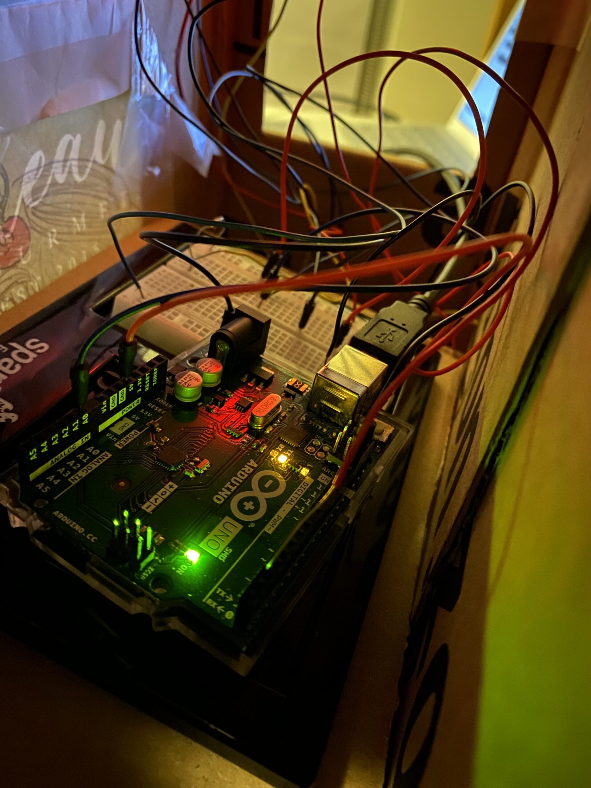
The Process, Beginning With Arduino:
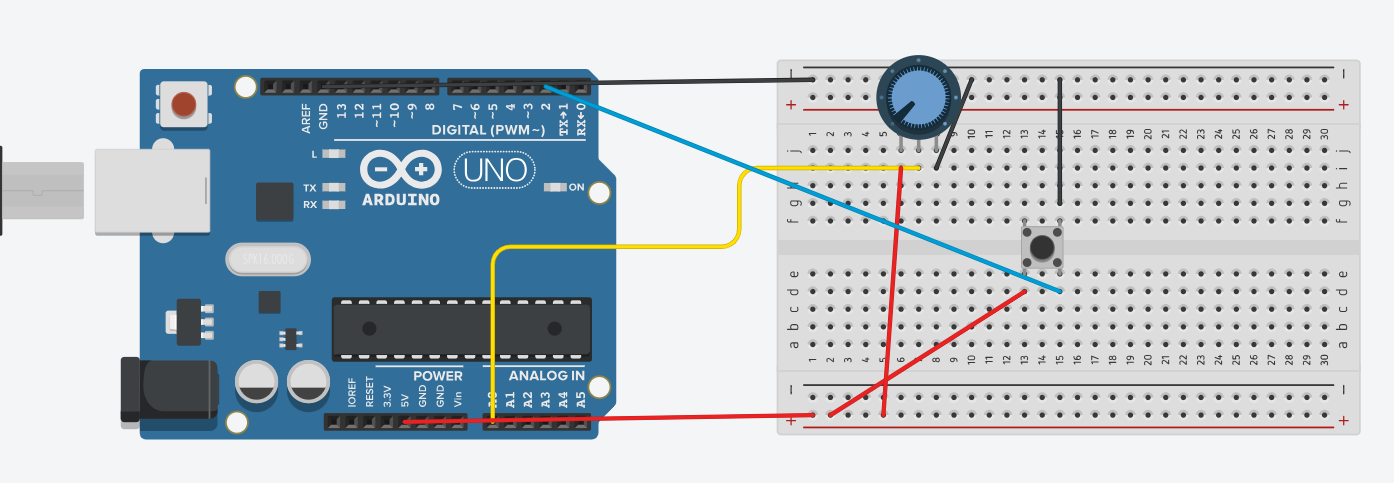
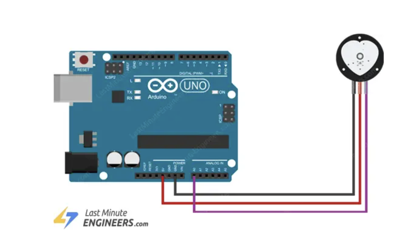
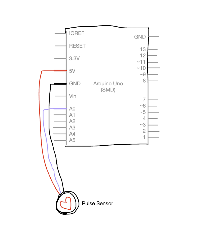
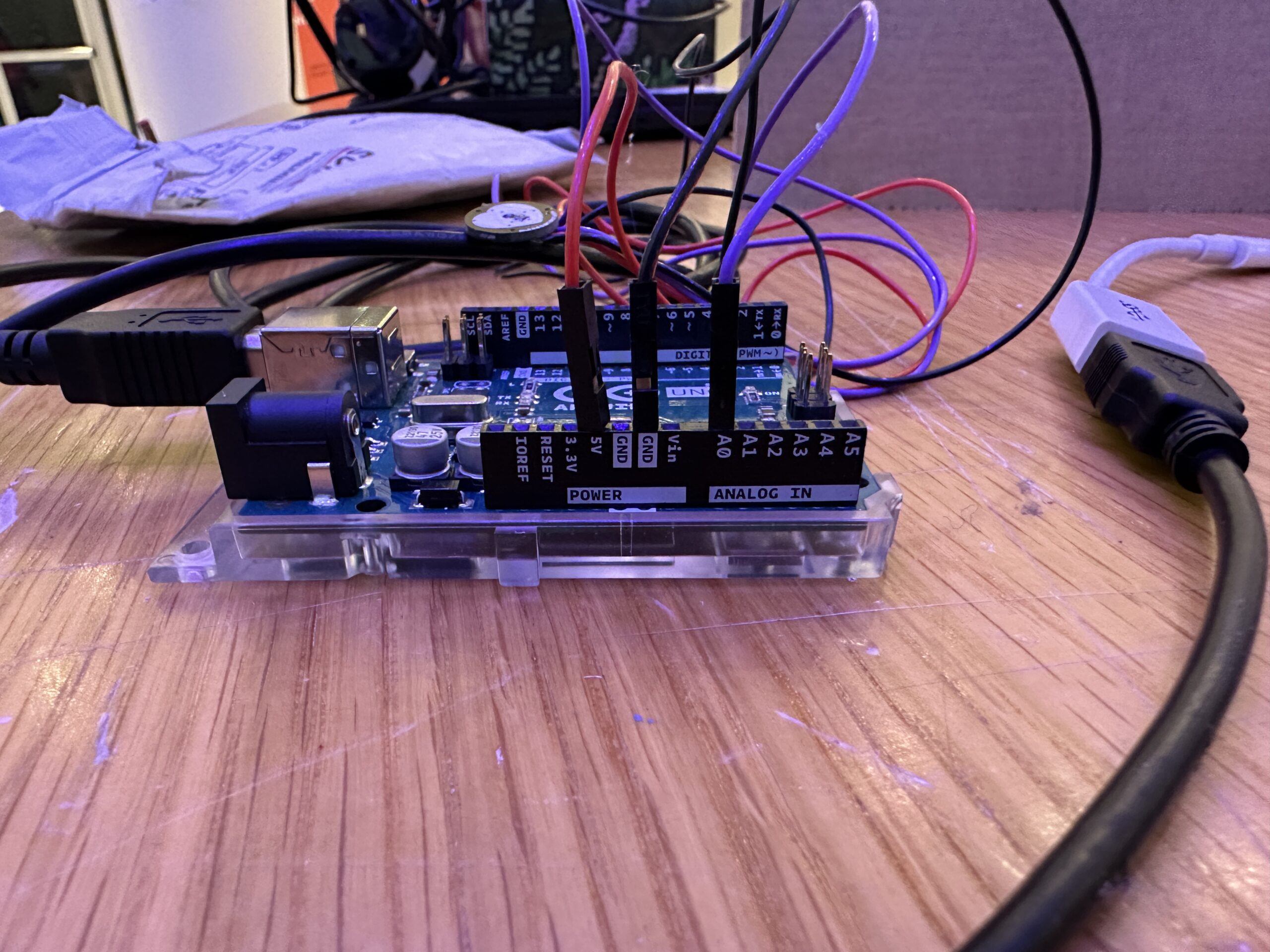
I started by tackling the Arduino part of the project. I followed a page linked here, which, thankfully, contained the exact instructions I needed. I followed the schematic they displayed, see below:
But I also drew my own schematic, here:
But here is an actual photograph, just to be sure:
The Arduino wiring couldn’t have been more simple. And frankly, the Arduino coding wasn’t that much more difficult either. I downloaded a PulseSensor library that I found on the page and made modifications to format the code for my own objectives. Here’s the code below:
void setup() {
  Serial.begin(9600);
  pinMode(LED_BUILTIN, OUTPUT);
  // Arduino sending data to component, the green light, to light up

  // start the handshake
  while (Serial.available() <= 0) {
    digitalWrite(LED_BUILTIN, HIGH);
    Serial.println("0,0");
    delay(300);
    digitalWrite(LED_BUILTIN, LOW);
    delay(50);
  }
}

void loop() {
  while (Serial.available()) {
    digitalWrite(LED_BUILTIN, HIGH);
    int left = Serial.parseInt();
    int right = Serial.parseInt();
 // Example of parsing, where Arduino breaks down left and right components so that when it sends the code to P5JS, P5JS interprets the left and right as one so that the code can be executed smoothly
    if (Serial.read() == '\n') {
      int pulseSensor = analogRead(A0);
// Mapping analog values to digital values so pulse sensor can be read and show up on P5JS
      int mappedPulseSensor = map(pulseSensor, 0, 1023, 0, 255);
      delay(5);
      Serial.print(mappedPulseSensor);
      Serial.print(',');
      Serial.println(mappedPulseSensor);
    }
  }
  digitalWrite(LED_BUILTIN, LOW);
}
The most important section worthy of mention is the mapping of the pulse sensor to a digital range. Apart from the voltage and ground wires, because the pulse sensor reads analog signals, I plugged the last wire into A0 and then mapped its 0 to 1023 range to 0 to 255, so that P5JS could read its detections and convert them into the pulses of the ellipse on the screen.
The Process, Continuing With P5JS:
The most challenging section of this project was the coding regarding P5JS. I started by coding a glowing ellipse and making sure that it pulsed with the readings of the sensor, linked here, but also shown below:
let rVal = 0;
let pulse = 255;
let left = 0;
let right = 0;


function setup() {
  createCanvas(600,600);
  textSize(18);
}

function draw() {
  // one value from Arduino controls the background's red color
  background(0);

  // the other value controls the text's transparency value
  fill(255, 255, 255);
  strokeWeight(0);

  if (!serialActive) {
    text("Press Space Bar to select Serial Port", 20, 30);
  } else {
    text("Connected", 20, 30);
  }


  drawingContext.shadowBlur = 80;
  drawingContext.shadowColor = color(255);
  ellipse(width/2, height/2, map(pulse, 0, 255, 10, 100))


}


function keyPressed() {
  if (key == " ") {
    // important to have in order to start the serial connection!!
    setUpSerial();
  }
}

// This function will be called by the web-serial library
// with each new *line* of data. The serial library reads
// the data until the newline and then gives it to us through
// this callback function
function readSerial(data) {
  ////////////////////////////////////
  //READ FROM ARDUINO HERE
  ////////////////////////////////////

  if (data != null) {
    // make sure there is actually a message
    // split the message
    let fromArduino = split(trim(data), ",");
    // if the right length, then proceed
    if (fromArduino.length == 2) {
      // only store values here
      // do everything with those values in the main draw loop
      rVal = fromArduino[0];
      pulse = fromArduino[1];
      print(pulse);
    }

    //////////////////////////////////
    //SEND TO ARDUINO HERE (handshake)
    //////////////////////////////////
    let sendToArduino = left + "," + right + "\n";
    writeSerial(sendToArduino);
  }
}
I coded the ellipse in the above section, making sure to map the diameter of the ellipse to the signals of the sensor, causing the pulsing effect. The section regarding how P5JS read the information from Arduino, but also sent information back to Arduino (see Handshake), so that Arduino and P5JS worked in tandem to make the ellipse pulse.
The Process, Continuing With P5JS:
After sorting out the ellipse pulsing, which was the main component, I began coding the stars and words I wanted to go along with the pulsing ellipse. I was really inspired by Pierre’s midterm project, because it gave that same all-encompassing starry night effect that Schneider’s installation did. I began by trying to make modifications to Pierre’s code, seen here, but I quickly realized after trying to insert the ellipse into it that coding within the constraints of WEBGL would be too difficult for me for the purposes of this project. While experimenting, I accidentally created this, which might be one of the coolest things I’ve ever made. I plan to pursue WEBGL on my own time, but I acknowledged that working within a two-dimensional realm for this project would suffice.
So, I began by coding the stars, linked here. I’ve attached the most difficult section of the code below:
function createStars() {
  for (let i = 0; i < 100; i++) {
    let x = random(width);
    let y = random(height);
    let radius = random(1, 3);
// I made the radius random within these constraints so the ellipses weren't all the same size, giving that 'starry night' effect and the illusion of distance, since I couldn't hack WEBGL
    let speedX = random(1, 3) * (random() > 0.5 ? 1 : -1); // So that the stars randomly go left and right
    let speedY = random(1, 3) * (random() > 0.5 ? 1 : -1); // So that the stars randomly go up or down
    stars.push({ x, y, radius, speedX, speedY });
  }
}

function moveStars() {
  for (let star of stars) {
    star.x += star.speedX;
    star.y += star.speedY;

    // Makes the stars stay within the constraints of the display screen
    if (star.x < 0 || star.x > width || star.y < 0 || star.y > height) {
      star.x = random(width);
      star.y = random(height);
    }
I wanted the size to be random within the constraints of 1 and 3 so that I could give the ellipses that ‘starry night’ effect. Making their radiuses vary also gave the illusion of depth and distance, since I couldn’t hack WEBGL. I made their movement as random as I could, making them go in different directions so I could add as much dynamism to the project as possible. The focus of the project, the fixed ellipse, is not that moving and stimulating, so I knew I needed to make the stars add that layer of movement to make sure the project would be engaging.
After coding the stars, I combined the code of that with the pulsing ellipse so that I could begin adding the words.
The Result!!!!
And this was the result! Linked here, but also seen below!
let rVal = 0;
let pulse = 255;
let left = 0;
let right = 0;
let stars = [];
let ellipseVisible = false;
let starsVisible = false;
let keyPressedOnce = false;
let showAdditionalText = false;
let mPressed = false;

function setup() {
  createCanvas(2000, 1300);
  textSize(34);
  createStars();
}

function draw() {
  background(0);
  fill(255);
  textAlign(CENTER, CENTER);


//Code that ensures that the instructions for the interaction, and the serial port appear before the ellipse and stars appear
  if (!serialActive) {
    text("PRESS SPACE TO SELECT SERIAL PORT", width / 2, height / 2);
  } else if (!ellipseVisible && !starsVisible) {
    text("LIGHTLY TOUCH YOUR FINGER TO THE PULSE SENSOR", width / 2, height / 2);
  } else if (ellipseVisible || starsVisible) {

//Responsible for making the ellipse glow
    drawingContext.shadowBlur = 80;
    drawingContext.shadowColor = color(255);
// Maps ellipse to arduino board, making it pulse
    let ellipseSize = map(pulse, 0, 255, 10, 300);
// Determines dimensions of ellipse
    ellipse(width / 2, height / 2, ellipseSize);
  }

// Once the ellipse and stars appear, the text taking you through the interaction appears too
  if (ellipseVisible && !starsVisible) {
    text("GIVE THE SENSOR TIME TO PICK UP ON YOUR PULSE\nBUT ONCE YOU SEE YOUR HEART BEATING, ACKNOWLEDGE\nTHAT THIS PULSE IS YOU, ALIVE AND BREATHING\n\nPress 'n'", width / 2, height - 180);
  } else if (starsVisible && !keyPressedOnce) {
// ensures that the stars appear and keep moving with each frame
    moveStars();
    displayStars();
    text("YOU ARE ALIVE AND BREATHING IN THE UNIVERSE\nLOOK AT AT ALL THE STARS\nBUT SOMETIMES, THE UNIVERSE SEEMS SO BIG\n IT'S EASY TO FEEL SMALL\n\nPress 'm'", width / 2, height - 180);
  } else if (starsVisible && !showAdditionalText) {
    moveStars();
    displayStars();
    text("BUT THE UNIVERSE IS ALIVE WITH YOU TOO\n\nPress 'v'", width / 2, height - 180);
  } else if (showAdditionalText) {
    moveStars();
    displayStars();
    text("TELL YOUR FRIENDS YOU LOVE THEM\nREMEMBER TO FEEL YOUR HEARTBEAT WHEN YOU\n LOOK UP AT THE SKY, BECAUSE SOMEDAY\nYOU'LL WISH YOU COULD'VE LIVED IT ALL OVER AGAIN", width / 2, height - 180);
  }
}

function createStars() {
// Defines speed and number of stars
  for (let i = 0; i < 100; i++) {
    let x = random(width);
    let y = random(height);
// Makes sure the stars are randomly different sizes within these constraints to give them that 'starry sky' effect
    let radius = random(1, 3);
// Defines random speed of stars within these constraints
    let speedX = random(1, 3) * (random() > 0.5 ? 1 : -1);
    let speedY = random(1, 3) * (random() > 0.5 ? 1 : -1);
    stars.push({ x, y, radius, speedX, speedY });
  }
}

function moveStars() {
  for (let star of stars) {
// After the speed of the stars has been defined, use moveStars to make sure they keep moving through the entire project
    star.x += star.speedX;
    star.y += star.speedY;

// Makes sure stars move within the display screen
    if (star.x < 0 || star.x > width || star.y < 0 || star.y > height) {
      star.x = random(width);
      star.y = random(height);
    }
  }
}

// Ensures the stars never disappear with each changing slide
function displayStars() {
  noStroke();
  for (let star of stars) {
// Makes stars glow after key 'm' is pressed
    if (mPressed) {
      fill(255, 255, 255, 180);
// Defines the size of the shadow that gives the stars their 'glow' effect
      ellipse(star.x, star.y, star.radius * 7);
      // for (i = 0; i < 100; i++) {
      //   ellipse(star.x, star.y, (star.radius * i * 1) / 20);
      // }
    }
    fill(255);
    ellipse(star.x, star.y, star.radius * 2, star.radius * 2);
  }
}

// My attempt to make the stars pulse, but I was okay with them simply glowing, so I never used updateStars but I kept it just in case
function updateStars() {
  let rValMapped = map(rVal, 0, 255, -0.1, 0.1);
  let pulseMapped = map(pulse, 0, 255, 1, 3);
  let pulsingFactor = map(pulse, 0, 255, 0.5, 2);

  for (let star of stars) {
    star.speedX += rValMapped;
    star.speedY += rValMapped;

    star.radius = pulseMapped * pulsingFactor;
  }
}


// These are all the instructions so that the project knows to move to the next slide when certain kets are pressed
function keyPressed() {
  if (key == " " && !serialActive) {
    setUpSerial();
  } else if (key == "n" && ellipseVisible && !starsVisible) {
    starsVisible = true;
  } else if (key == "m" && starsVisible && !mPressed) {
    keyPressedOnce = true;
    mPressed = true;
  } else if (key == "m" && starsVisible && mPressed) {
    mPressed = false;
  } else if (key == "v" && starsVisible && keyPressedOnce) {
    showAdditionalText = true;
//Code that allows one to exit our of and enter fullscreen by pressing the key 'f'
  } else if (key == "f") {
    if (!fullscreen()) {
      fullscreen(true);
    } else {
      fullscreen(false);
    }
  }
}

// How P5JS knows to read from Arduino in order to give the ellipse the pulse
function readSerial(data) {
  if (data != null) {
    let fromArduino = split(trim(data), ",");
    if (fromArduino.length == 2) {
      rVal = fromArduino[0];
//The pulse from Arduino that P5JS was able to read to make the ellipse pulse
      pulse = fromArduino[1];
    }

    let sendToArduino = left + "," + right + "\n";
    writeSerial(sendToArduino);
// If a pulse greater than 0 is detected from the sensor and the ellipse is visible, then the pulsing begins
    if (pulse > 0 && !ellipseVisible) {
      ellipseVisible = true;
    }
  }
}


// Ensures stars and ellipse stay visible when mouse is pressed
function mousePressed() {
  if (!starsVisible && ellipseVisible) {
    keyPressedOnce = true;
    starsVisible = true;
  }
}
I commented everything, but the most difficult part of the code was definitely this section:
// Once the ellipse and stars appear, the text taking you through the interaction appears too
  if (ellipseVisible && !starsVisible) {
    text("GIVE THE SENSOR TIME TO PICK UP ON YOUR PULSE\nBUT ONCE YOU SEE YOUR HEART BEATING, ACKNOWLEDGE\nTHAT THIS PULSE IS YOU, ALIVE AND BREATHING\n\nPress 'n'", width / 2, height - 180);
  } else if (starsVisible && !keyPressedOnce) {
// ensures that the stars appear and keep moving with each frame
    moveStars();
    displayStars();
    text("YOU ARE ALIVE AND BREATHING IN THE UNIVERSE\nLOOK AT AT ALL THE STARS\nBUT SOMETIMES, THE UNIVERSE SEEMS SO BIG\n IT'S EASY TO FEEL SMALL\n\nPress 'm'", width / 2, height - 180);
  } else if (starsVisible && !showAdditionalText) {
    moveStars();
    displayStars();
    text("BUT THE UNIVERSE IS ALIVE WITH YOU TOO\n\nPress 'v'", width / 2, height - 180);
  } else if (showAdditionalText) {
    moveStars();
    displayStars();
    text("TELL YOUR FRIENDS YOU LOVE THEM\nREMEMBER TO FEEL YOUR HEARTBEAT WHEN YOU\n LOOK UP AT THE SKY, BECAUSE SOMEDAY\nYOU'LL WISH YOU COULD'VE LIVED IT ALL OVER AGAIN", width / 2, height - 180);
  }
Making the words appear in the order I wanted, without the ellipse or stars disappearing was difficult and something I had to work at for a while. I solved this by coding successive “if, else” statements and establishing this:
let starsVisible = false;
let keyPressedOnce = false;
let showAdditionalText = false;
at the beginning of the code. My friend Zion helped me extensively through this part of the coding, so thank you Zion.
After that, I just had to make the small adjustments of making the text the size I wanted, adjusting the stars to full screen, and the project was good to go. I didn’t know how to upload the song I wanted, “Stone in Focus” by Aphex Twin, as a file to P5JS, so I just played it in a Youtube tab while the project was going on.
I also made the stars glow with the ellipse when the line “BUT THE UNIVERSE IS ALIVE WITH YOU TOO” to give a sense of connection with the universe. The stars got triggered to glow after pressing the ‘m’ key.
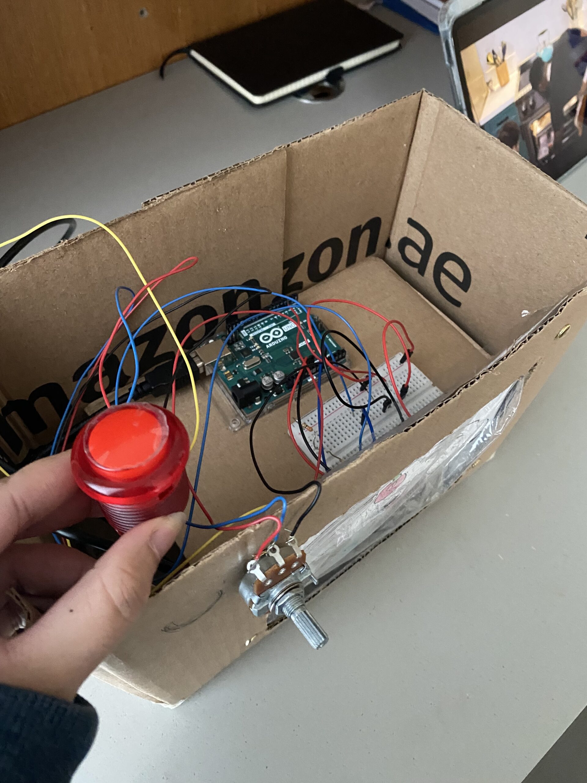
Showcase Day:
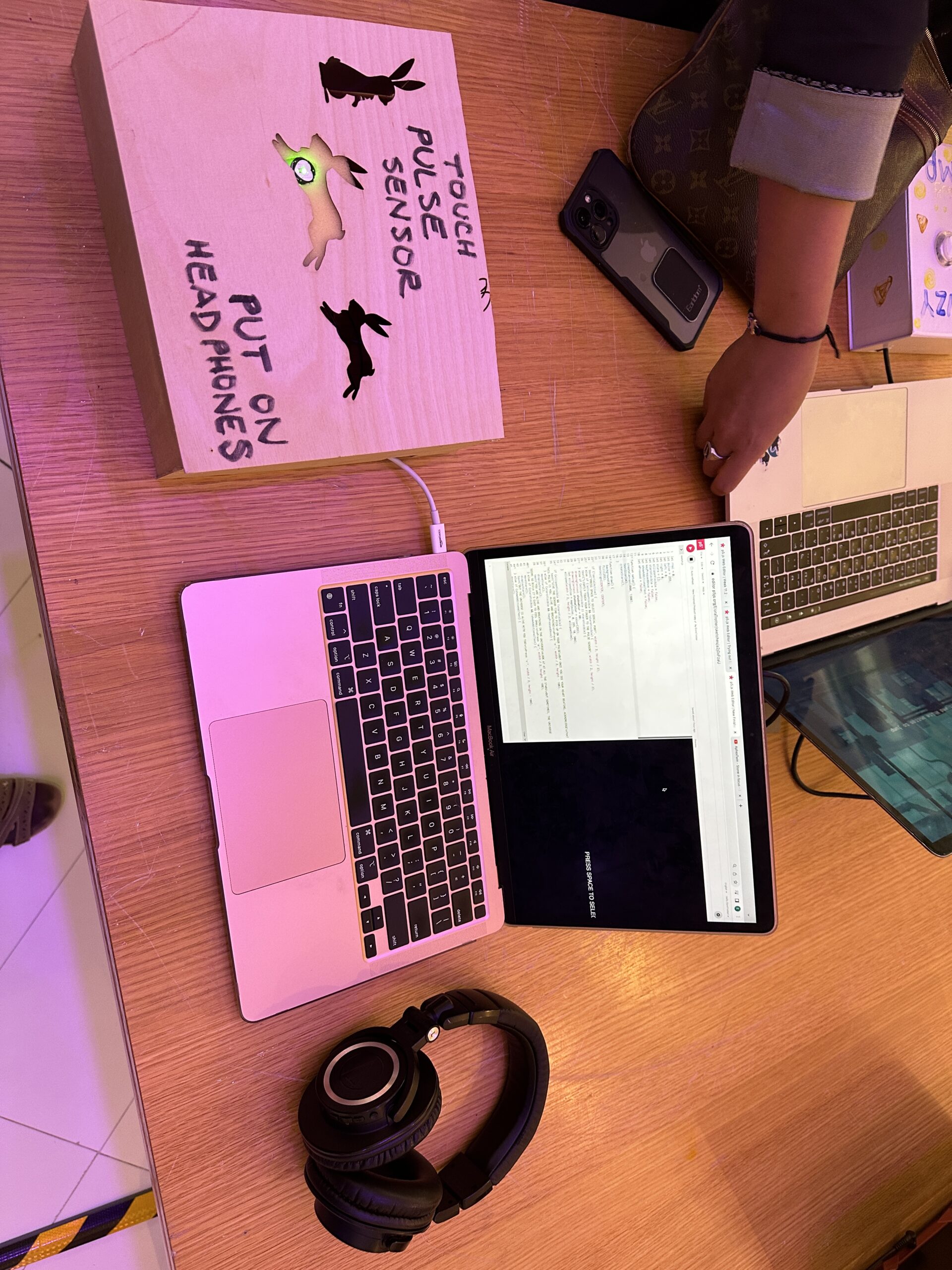
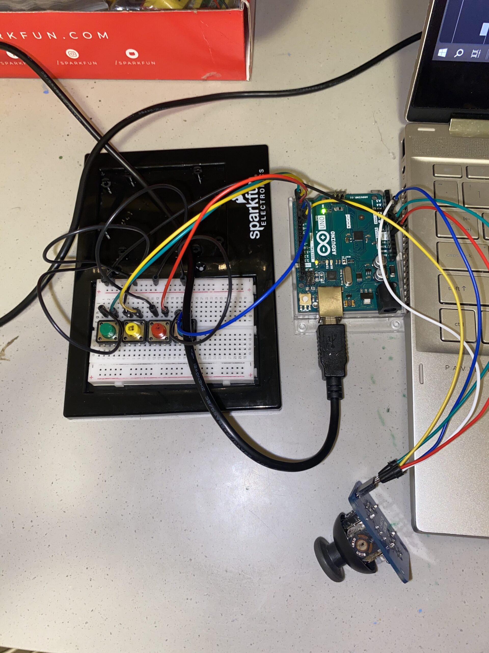
On the day of the showcase, I constructed my setup, seen here:
You can see the headphones that people put on to hear the music, but I want to bring special attention to the box:
One of my biggest concerns developing the project was the unreliability of the pulse sensor itself. It would reliably pick up on a pulse but also pick up on any extra movement of your hand, making the pulse look wonky. It’s because the pulse sensor works by shining a light on your finger, and reading your pulse by the way it affects the light. So if you move your finger too much, it disrupts the pulse sensors ability to pick up on your heartbeat. At Manar Abu Dhabi, even that pulse sensor had to wait up to a few minutes before being able to get a stable reading. So, creating better pulse sensors for future interactive installations is a concern. But in order to counteract this problem, I constructed a box that the audience member could naturally rest their hands on so that the pulse sensor could pick up a more stable reading. It also looked more approachable and finished as an interactive installation.
One concern I left with though, from a design point of view, was that people tended to put their their right hand on the sensor, causing them to have to reach over with their left hand to press the keys to go through the project. I would want to make my project more convenient and interactive by fixing this issue.
Takeaways:
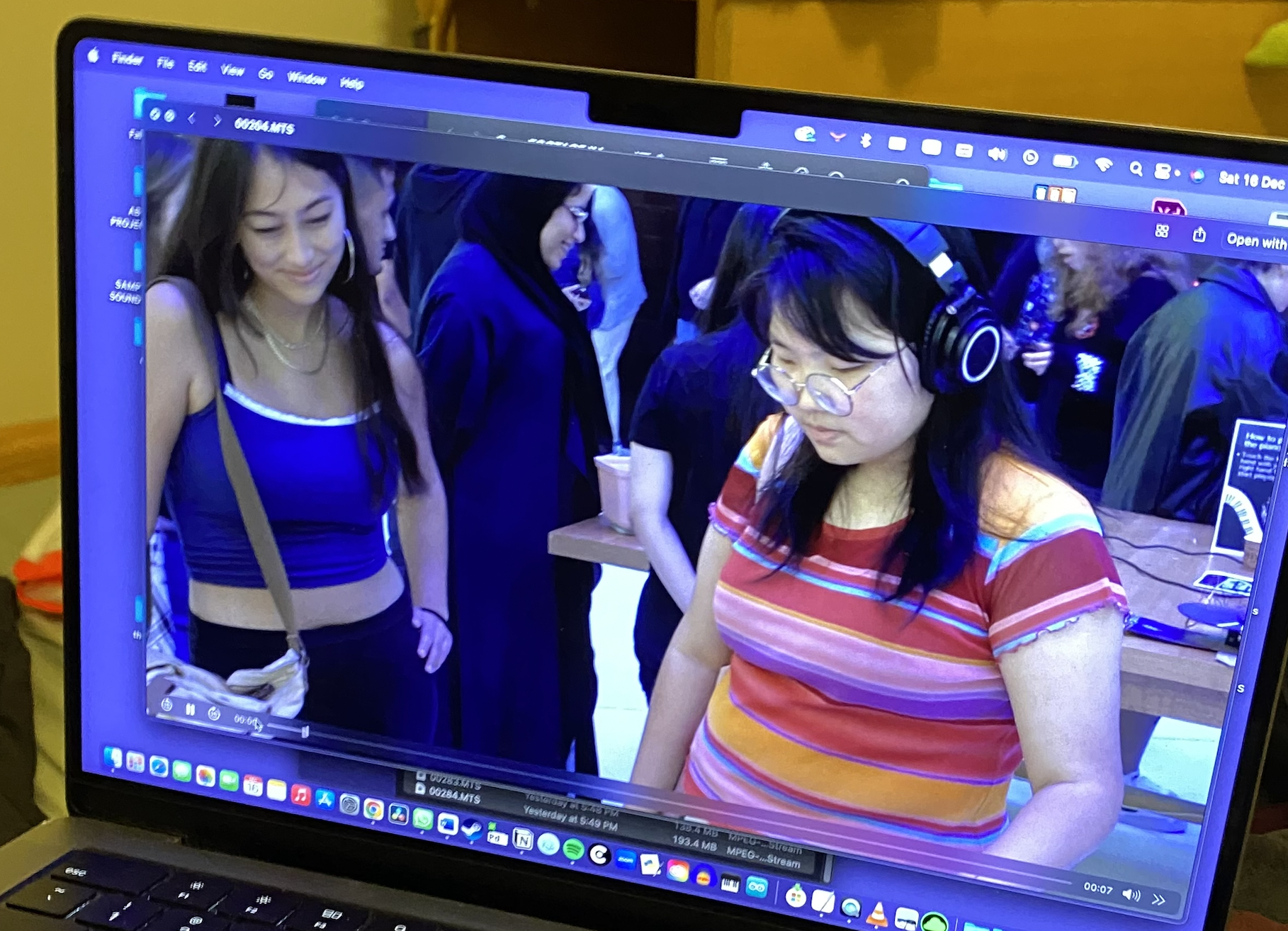
In the end, I am so proud of what I made, because I was able to capture an, albeit small, portion of the feeling that I experienced when at Schneider’s installation and Manar Abu Dhabi. Here are some people interacting with my project:
What they’re going through, is seeing their pulse on the screen and then reading successive phrases that remind them of their connection with the universe, giving them that same macro-micro spiritual connection that Andrew Schneider’s installation gave me. One of my favorite moments was when Linda, an audience member, saw her pulse on the screen and gasped, “It’s me!” That’s the exact effect I wanted to provide.
At the beginning of this post, I posted a picture of Mega and me. After she had completed the project, she turned to me and said, “Elora, I love you.” Even though the effect was small, I had emotionally achieved what I set out to do with this project, and I am so grateful.
It was pretty exciting to see my roommate and friend dive into the project I’ve been working on. They handled it surprisingly well, navigating through most of it without needing any pointers from me. That’s a good sign that things are intuitive. Most parts of the project seemed to flow smoothly for them, but the joystick part caused a bit of confusion. This is something I would need to focus on especially for those who aren’t familiar with sliding puzzles. I’m sure making that clearer would make it more user-friendly and increase useability. Once I explained the basic instructions—reading the guidelines and hitting the right buttons—they seemed to sail through the rest. Straightforward instructions can really make a difference. There are definitely some areas I want to improve. The shuffling aspect of the puzzle needs tweaking. Sometimes, it gets all twisted up in a way that makes it impossible to solve. It’s on my list of things to work on. Also, those key press functions need fixing. Having to stop and restart the whole thing instead of a simple button press for a restart can be a hassle. So these are things that I am definitely working on for improvement. But overall, I’m pretty proud of where the project stands. It feels good to be at a comfortable point, just needing a few tweaks to make it even better. Excited to keep refining it.
I love baking, and I enjoy baking games. For my final project I decided to make a pie shop… Throughout my journey in Intro to IM, I made sure to always add a piece of me in every assignment and project. This final one is especially dear to me because I was able to finalize it after hard work. As well as being able to add my art in it (background and pie images). I think it goes well together and I’m proud of it.
FUN FACT: I have never had pie in my life!!!
Highlight OF MY Code in P5.js:
-Function to check the correct match
function submitAnswer() {
  // Define the expected ranges for each statement
  const rawRange = [0, 200];
  const undercookedRange = [201, 400];
  const perfectRange = [401, 600];
  const overcookedRange = [601, 800];
  const burntRange = [801, 1023];

  let expectedRange;

  // Determine the expected range based on the current sentence
  switch (currentSentence) {
    case "I would like a raw pie to bake at home.":
      expectedRange = rawRange;
      break;
    case "I like my pie extremely soft.":
      expectedRange = undercookedRange;
      break;
    case "I want a perfect pie!":
      expectedRange = perfectRange;
      break;
    case "Crispy around the edges!!":
      expectedRange = overcookedRange;
      break;
    case "BURNT IT >:D":
      expectedRange = burntRange;
      break;
  }

  // Check if the current image range matches the expected range
  if (x >= expectedRange[0] && x <= expectedRange[1]) {
    // Increment the score for a correct match
    score++;

  ding.play();
-Different screen pages:
if (gameState === "start") {
  drawStartScreen();
} else if (gameState === "playing") {
  displayFoodImage();
  displayTimer();
  textSize(24);
  fill(255);
  text("Score: " + score, width - 100, 30);
} else if (gameState === "end") {
  // Display results in the end screen
  textSize(210);
  fill(255);
  text("Your Score: " + score, width / 2, height / 2);
  playAgainButton.show(); // Show the button on the end screen
}
else {
  // Draw other game elements here
  playAgainButton.hide(); // Hide the button if not in the end state
}
Arduino IDE Code:
int potPin = A0;      // Potentiometer connected to analog pin A0
int buttonPin = 2;    // Digital button connected to digital pin 2

void setup() {
  Serial.begin(9600); // Set the baud rate to the same value as in p5.js
  pinMode(buttonPin, INPUT_PULLUP); // Set the digital button pin as input with internal pull-up resistor
}

void loop() {
  int potValue = analogRead(potPin); // Read potentiometer value (0 to 1023)
  int buttonState = digitalRead(buttonPin); // Read button state (HIGH or LOW)
  Serial.print(potValue); // Send potentiometer value to p5.js
  Serial.print(',');
  Serial.println(buttonState); // Send button state to p5.js

  delay(550);
}
Components:
-LED Button
-Potentiometer
OveN Prototype and schematics:
User Testing:
Challenges:
Many challenges were faced with the coding part.
Button wasn’t working to confirm answers and also change the requests of the order.
Sometimes the images controlled by the potentiometer would not show, or not change.
I also had some issues with serial connection because of the wirings
Future Imporvements:
I hoped to be able to make the game restart without having to exit full screen.
Make the prototype a little prettier
Fine-tune the difficulty level based on user feedback. Adjust timer durations, scoring mechanisms, or image recognition ranges to make the game challenging yet enjoyable.
Introduce new challenges or power-ups to add variety to the gameplay.
Ensure that the game is responsive and looks good on various screen sizes.
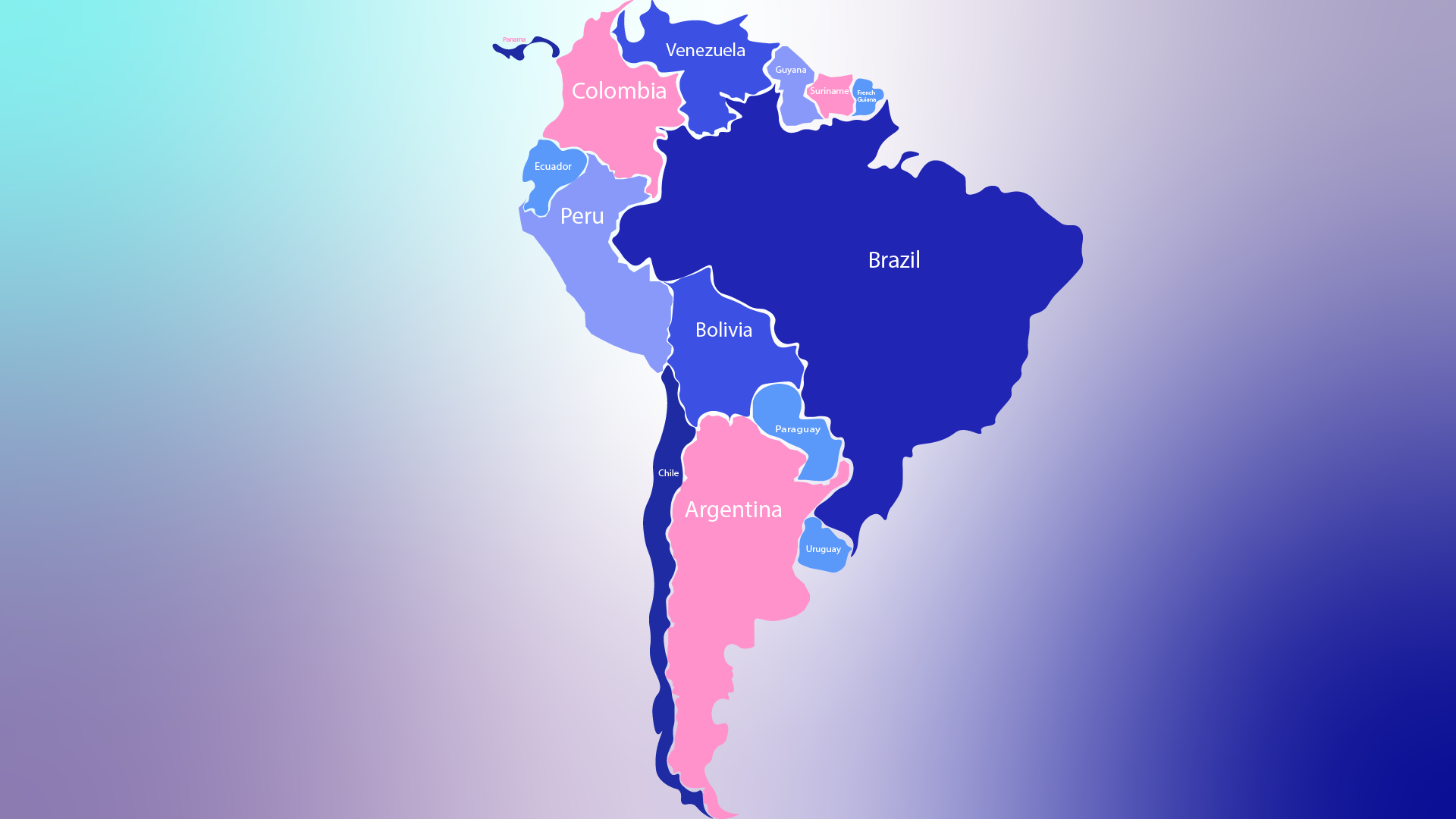
IMG_7438For my final project, I had to last minute change the concept since my midi controller idea fell through and proved to be unfit for this assignment. My project now is a musical map that lets users play music from different regions of the world. I initially wanted to create a map of the globe but decided to consolidate my map into one continent. The continent I chose was South America (SA). South America resonated with me the most because of my love of Latin American music! I initially was going to take an image of the map from off of the internet but decided to design my own map of SA. This was designed in Adobe Illustrator.
I picked a total of 13 songs all from different parts of SA:
Brazil: Dindi – Sylvia Telles
Venezuela: Mi Corazon – Los Melodicos
Colombia: Tobaco y Ron – Rodolfo y su typica ra7
Ecuador: Escribeme – Tierra Canela
Suriname: Moi Misi – Sabokoe
Guyana: Catch me Lova – JMC
French Guiana: Kraze Dj Action X Jaydieff
Peru: Peru de Valses: Y se llama Peru – Oscar Avilles
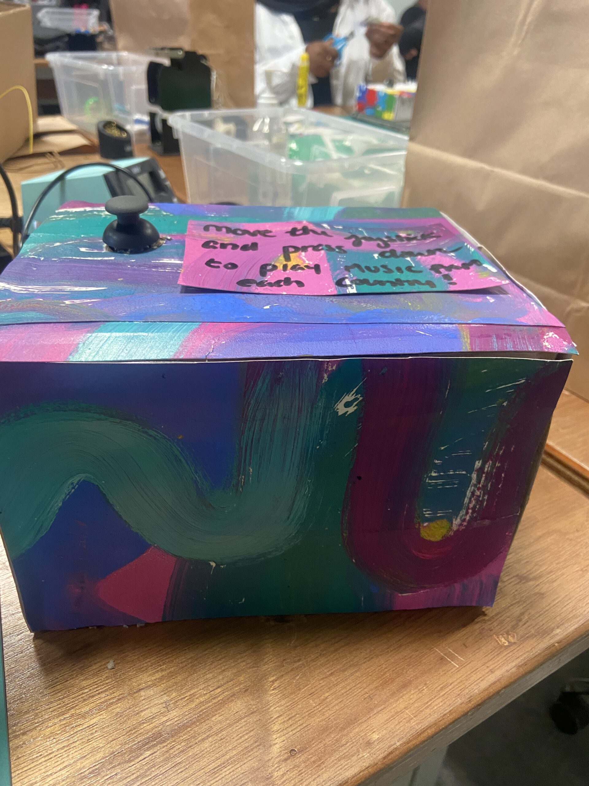
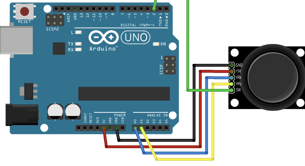
Users simply can move the joystick, which acts as a cursor on the screen and press on the squares in the p5 sketch to trigger a unique sound file from each country.
Aesthetic Design:
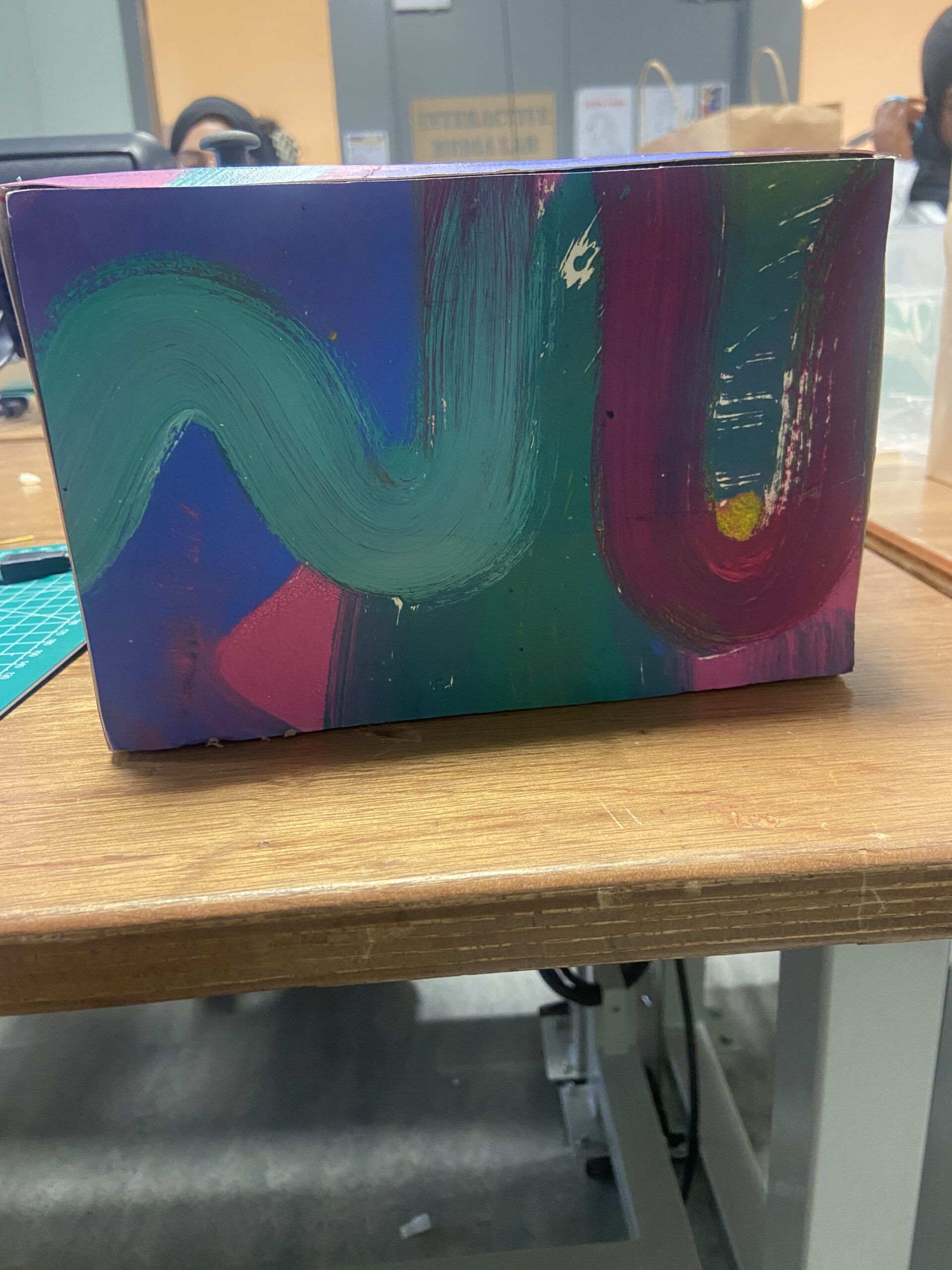
I made my box out of cardboard and painted on several separate sheets of paper a similar color scheme to my digital design of the map. I then glued those pieces of paper onto the box!
I initially had quite a few issues in p5 trying to upload the song files. I realized that it was because I placed all the songs in a folder and P5 couldn’t find the path to that folder. I also had issues with organizing the square buttons on the screen, as well as cuing and pausing the music in combination with the joystick!
Improvements:
I would really like to make my p5 sketch a bit more elaborate and maybe add some sort of extra LED aspect to my arduino to make things a bit more exciting!
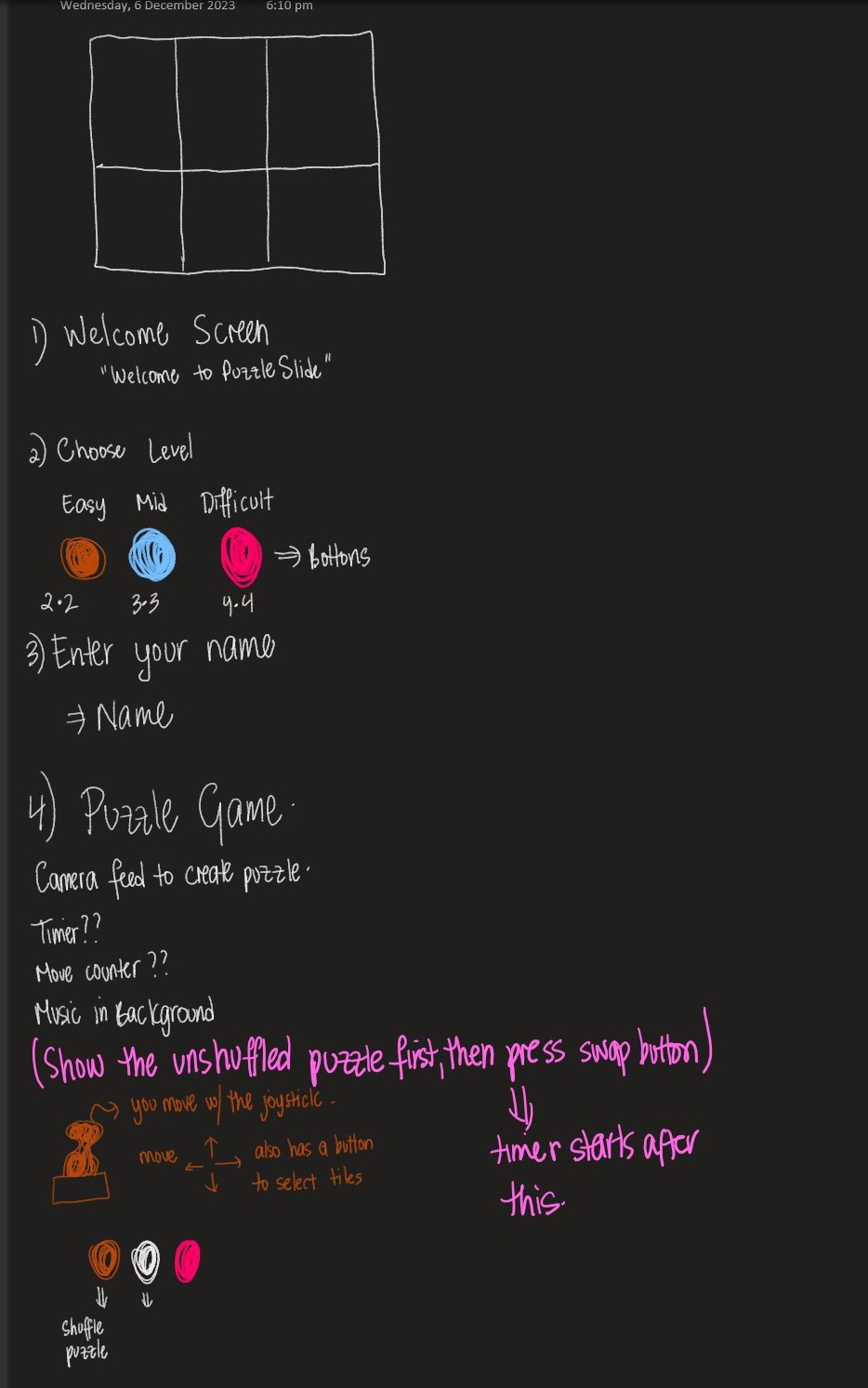
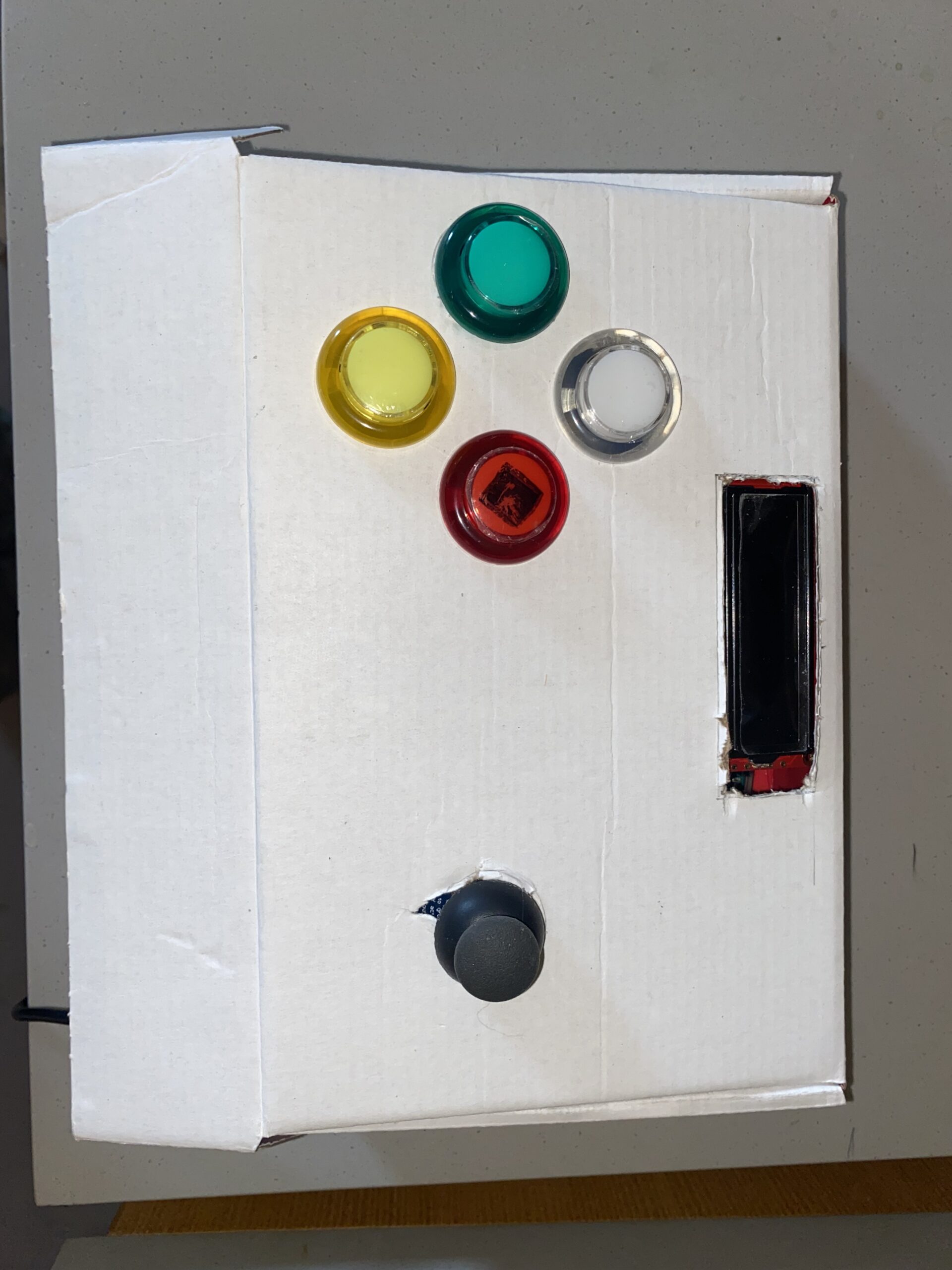
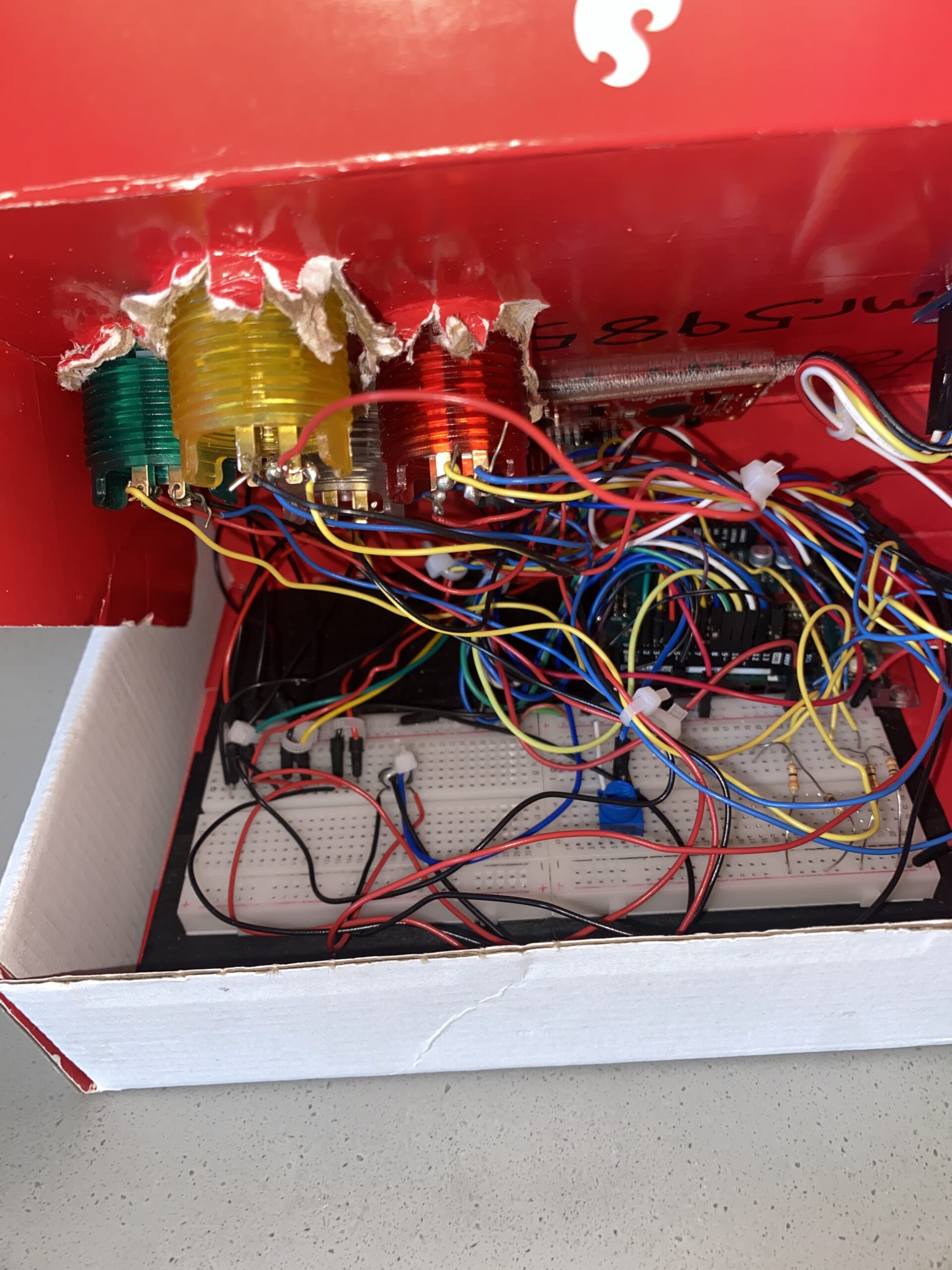
My project concept is one I came to fall in love with. I always liked the idea of taking pictures and so being able to create an interactive environment, where I am able to solve a puzzle using a picture I just took, I think is very fun. This I think is a metaphor for just how challenging but fun this class was. The puzzle could represent some of the challenges I faced throughout the class and building the puzzle represents the way in which my skills developed over the course of the 14 weeks. At the end when you look at the finished puzzle and feel proud of yourself for solving, represents how happy and proud I am of myself, not only to have finished the class, but having done so with new skills and I guess a love for physical computing. I feel like a genius, which is exactly what my LCD screen says when I complete the puzzle.
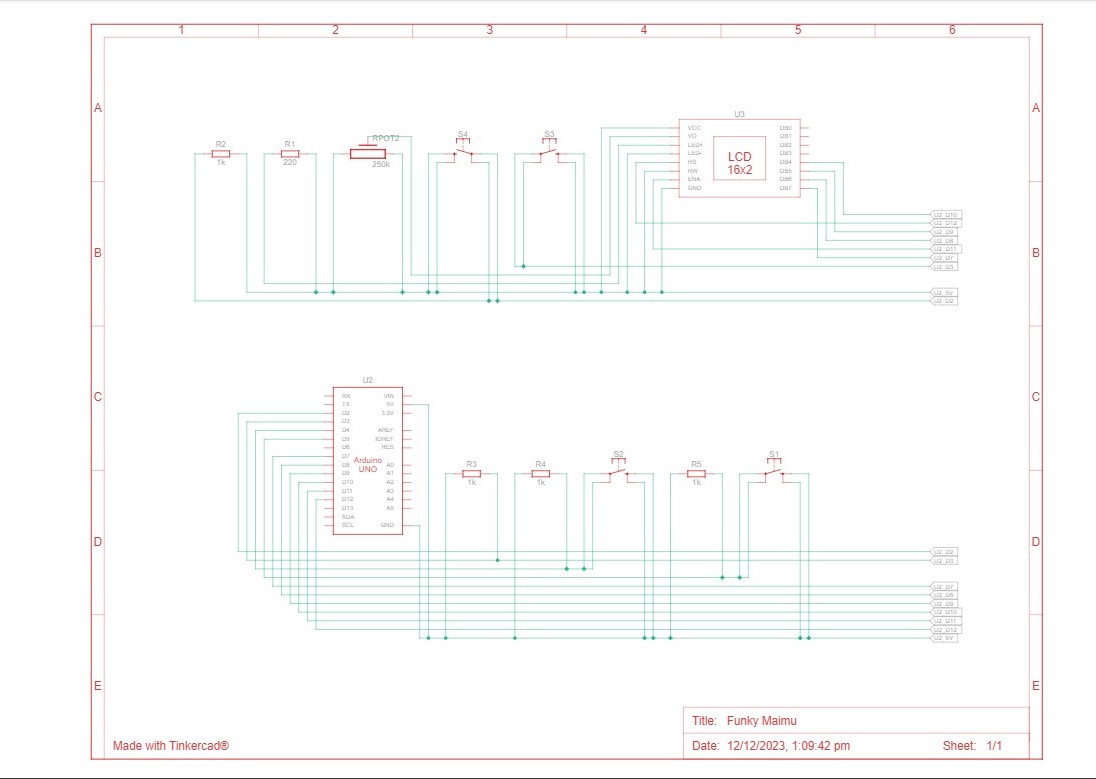
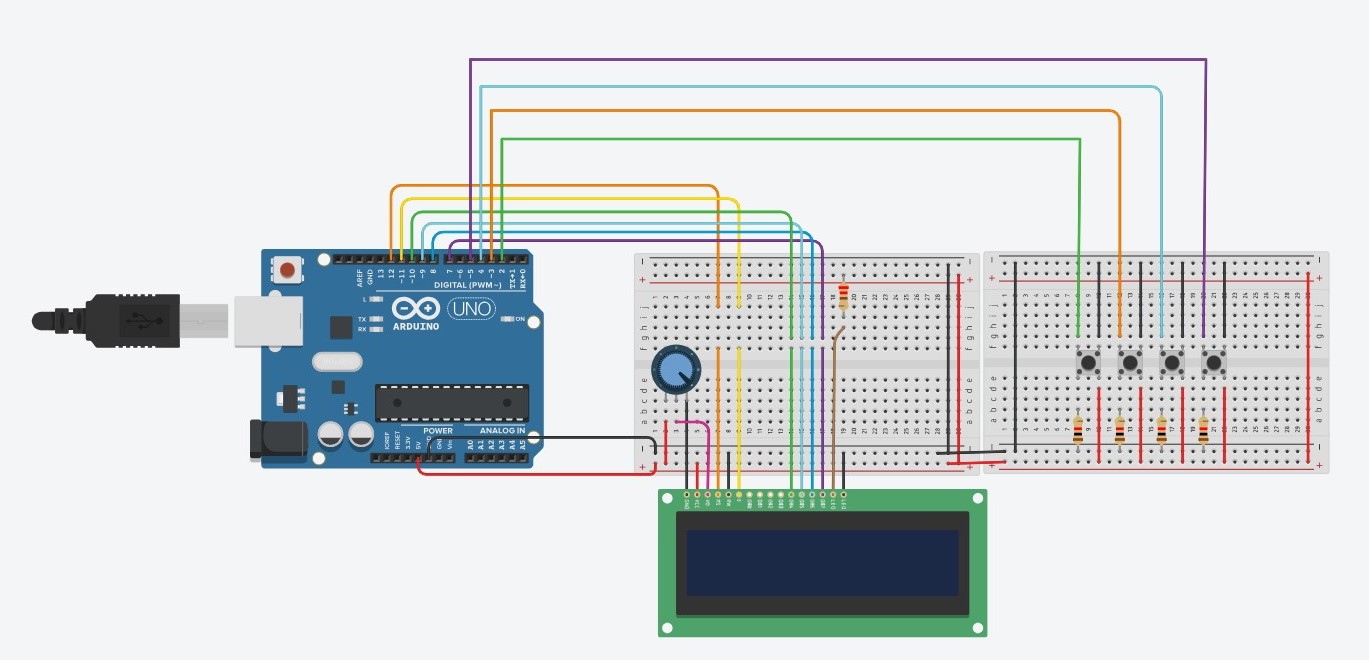
Schematic and Modelling:
Images of project:
User Testing videos:
How does the implementation work?
The project’s core idea is straightforward: manipulate the puzzle pieces using the joystick and follow on-screen instructions by pressing the buttons accordingly. The inspiration behind this setup actually came from the PS5 controller. I was dead set on incorporating a joystick into the design, and that sparked the whole concept.
Description of interaction design:
The design is meant to be user-friendly. I aimed for simplicity, assuming everyone knows the basics of a joystick. The on-screen instructions should guide players smoothly through the game. It’s a balance—simple enough for anyone to dive in yet not overly basic to bore them. That’s where the difficulty levels come in. I’ve got three, but I’ve only tested two myself, only managing to crack the first level. Give it a shot and see how far you can go!
Description of Arduino code + code snippets
The Arduino sketch I’ve got sets up a cool interface using buttons and a joystick to handle an LCD display and communicate using serial communication. First off, it gets things going by setting up pins for the buttons and joystick, along with initializing a LiquidCrystal display. The setup() function takes care of configuring serial communication, initializing pins, and prepping the LCD screen. The loop() function takes care of button presses and joystick moves. And when it detects these actions, it sends messages through serial communication. Each action—like a mouse click, difficulty level selection, joystick move, or even a command to snap a picture—is translated into a specific message. This sketch is a great listener too. It keeps an ear out for incoming messages through the serial port. When it gets specific ones like ‘TIMER:’, ‘MOVES:’, or ‘SOLVED’, it updates the LCD screen accordingly. So, you’ll see things like timer values ticking away, move counts racking up, and a sweet congratulatory message popping up when you crack that puzzle.
#include <LiquidCrystal.h>

const int XbuttonPin = 2;
const int SbuttonPin = 3;
const int TbuttonPin = 4;
const int CbuttonPin = 5;
const int joystickXPin = A0; // Analog pin for joystick X-axis
const int joystickYPin = A1; // Analog pin for joystick Y-axis
const int threshold = 50; // Threshold for joystick sensitivity
//bool isDifficulty = false;

LiquidCrystal lcd(6, 12, 11, 10, 9, 8);

void setup() {
  Serial.begin(9600);
  pinMode(XbuttonPin, INPUT_PULLUP);
  pinMode(SbuttonPin, INPUT_PULLUP);
  pinMode(TbuttonPin, INPUT_PULLUP);
  pinMode(CbuttonPin, INPUT_PULLUP);

  lcd.begin(16, 2);
  lcd.clear();
}

void loop() {
  if (digitalRead(XbuttonPin) == LOW) {
    Serial.println("MOUSE_CLICK");
    delay(1000); // Debounce delay
  }

  if (digitalRead(SbuttonPin) == LOW) {
    Serial.println('2');
    delay(100); // Debounce delay
  }

  if (digitalRead(TbuttonPin) == LOW) {
    Serial.println('1');
    delay(1000); // Debounce delay
  }

  if (digitalRead(CbuttonPin) == LOW) {
    Serial.println('3');
    delay(100); // Debounce delay
  }

  if (digitalRead(TbuttonPin) == LOW) {
    Serial.println('C');
    delay(100); // Debounce delay
  }

  int xVal = analogRead(joystickXPin); // Read X-axis value
  int yVal = analogRead(joystickYPin); // Read Y-axis value

  if (xVal < 512 - threshold) {
    Serial.println("LEFT");
    delay(500); // Debounce delay
  } else if (xVal > 512 + threshold) {
    Serial.println("RIGHT");
    delay(500); // Debounce delay
  }

  if (yVal < 512 - threshold) {
    Serial.println("DOWN");
    delay(500); // Debounce delay
  } else if (yVal > 512 + threshold) {
    Serial.println("UP");
    delay(500); // Debounce delay
  }
  if (Serial.available() > 0) {
    String message = Serial.readStringUntil('\n');

    if (message.startsWith("TIMER:")) {
      lcd.setCursor(0, 0);
      lcd.print(message.substring(6)); // Print the timer message
    } else if (message.startsWith("MOVES:")) {
      lcd.setCursor(0, 1);
      lcd.print("Moves: " + message.substring(6)); // Print the move counter message
    } else if (message == "SOLVED") {
      lcd.clear();
      lcd.setCursor(0, 0);
      lcd.print("You are a GENIUS!!!");
      delay(5000); // Display "Puzzle Solved!" for 2 seconds
      lcd.clear();
    }
  }
}
Description of p5.js code + code snippets + embedded sketch
My p5.js puzzle game lets you interact with images, customizable with varying difficulty levels. It progresses through welcome, instructions, and gameplay phases. The Puzzle class manages the game mechanics—moves, shuffling tiles, checking progress, and joystick input. The draw() function orchestrates screens, responding to commands from sources like Arduino. Background music sets the tone for welcome and instructions, fading during gameplay focus. The setup() function initializes the canvas, video feed, and initial puzzle grid, making it the core of this interactive experience.
function captureAndSetupPuzzle(video) {
  if (video) {
    source = video.get();
    source.loadPixels(); // Ensure pixels are loaded
 if (source.width > 0 && source.height > 0) {
    // Resize the source image to fit the canvas
    source.resize(width, height);
    video.hide();

    w = Math.floor(width / cols);
    h = Math.floor(height / rows);

    for (let i = 0; i < cols; i++) {
      for (let j = 0; j < rows; j++) {
        let x = i * w;
        let y = j * h;
        let img = source.get(x, y, w, h); // Get a portion of the image for each tile

        if (i === cols - 1 && j === rows - 1) {
          board.push(-1);
          puzzle.tiles.push(new Tile(-1, img));
        } else {
          let index = i + j * cols;
          board.push(index);
          puzzle.tiles.push(new Tile(index, img));
        }
      }
    }

    puzzle.board = board.slice();
    puzzle.simpleShuffle(puzzle.board);

    currentScreen = 'game';
    puzzle.startTimer();
  } else {
    console.error("Error loading the video source");
    }
  }
}
function joystick(puzzle, direction) {
  let xOffset = (width - puzzle.w * puzzle.cols) / 1.3;
  let yOffset = (height - puzzle.h * puzzle.rows) / 2.5;

  // Calculate the tile indices based on joystick direction
  let i = -1,
    j = -1;
  let blank = puzzle.findBlank();
  let blankCol = blank % puzzle.cols;
  let blankRow = Math.floor(blank / puzzle.rows);

  switch (direction) {
    case 'LEFT':
      i = blankCol + 1;
      j = blankRow;
      moveSound.play();
      break;

    case 'RIGHT':
      i = blankCol - 1;
      j = blankRow;
      moveSound.play();
      break;

    case 'UP':
      i = blankCol;
      j = blankRow + 1;
      moveSound.play();
      break;

    case 'DOWN':
      i = blankCol;
      j = blankRow - 1;
      moveSound.play();
      break;

    default:
      // Handle other cases or unknown commands
      break;
  }

  if (i >= 0 && i < puzzle.cols && j >= 0 && j < puzzle.rows) {
    puzzle.move(i, j, puzzle.board);
  }
  writeSerial("MOVES:" + puzzle.getMoves() + "\n");
 // puzzle.updateTimer(); // Update the timer
 // puzzle.displayTimer(); // Display the timer
}
Description of communication between Arduino and p5.js
In my project, the Arduino and p5.js are like buddies chatting through a USB connection using serial communication. The Arduino sends messages over to p5.js, which eagerly listens and understands what’s being said. Depending on these messages, p5.js swings into action—triggers different functions, or tweaks how the whole thing behaves. It’s like they’re choreographing a dance together! This connection allows the tangible aspects of my project—like button pushes or sensor readings from the Arduino—affect what happens on the digital playground of the p5.js sketch. It’s a smooth back-and-forth: the Arduino talks to p5.js, guiding its moves, while p5.js keeps the Arduino in the loop about how the game’s going—sending updates on moves made and puzzles solved. They’ve got this teamwork thing down, with the Arduino shaking things up in the digital world and p5.js keeping it informed about what’s happening in the game.
What are some aspects of the project that you’re particularly proud of?
One thing I’m really excited about is achieving two-way communication in my project. It was a bit of a hurdle because I’ve always been more comfortable with software like p5.js, which made tasks like controlling mouse clicks and key presses with Arduino a breeze. But the real challenge came when I needed to send information back from p5.js to the Arduino IDE. Figuring out how to establish that connection was a bit tricky, but once I got it working, it felt like a big win.
Another part that I’m super proud of is the capture process. Initially, I had the picture saved and then converted it into the grid. However, I realized this meant that everyone’s picture would end up stored on my laptop, and I wasn’t keen on that idea. So, I reworked the code to immediately convert the picture as soon as it’s taken. I love this feature because it ensures privacy by not saving anyone’s picture on my device, and it’s more immediate and seamless for the users.
One of the toughest parts I tackled was turning the picture into a grid and getting those tiles to shift around. The real challenge here wasn’t just making the picture the puzzle, but doing it on the spot—taking a photo and instantly turning it into a puzzle. It felt like a puzzle itself! For a while, I hit a roadblock. I could snap the picture, form the tiles, but they just wouldn’t budge. Turned out, they weren’t connecting to my puzzle class properly. It was like they were stuck in place. To fix this, I had to dive into the puzzle class and really fine-tune how the capturing worked. It was trial and error, a lot of experimenting. Then, I stumbled upon this function called video() in p5.js, and that was a game-changer. It helped me get things back on track and finally, my project started to click.
Future Work:
I’ve been thinking about how to take this project to the next level and turn it into more of a game. For me, this whole thing has been a way to relax and unwind, not really about competing. But I think adding a competitive element could make it way more interesting. I’ve been considering the idea of making it multiplayer, so that more than one player can get involved in the game. Imagine friends coming together, enjoying some puzzling challenges, and maybe even a bit of friendly competition. It could be a great way for them to hang out and have a good time. By making these changes, I believe it’ll become a fun escape for folks who enjoy puzzles or just want to kick back and have some light-hearted rivalry.
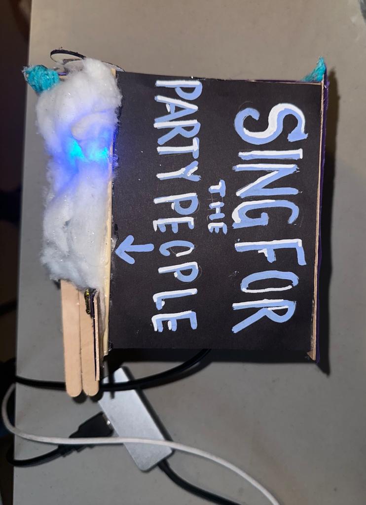
Reflecting on the user testing of my Mini Disco project with my friend, I found that the experience was quite self-explanatory and intuitive. The design, featuring an arrow pointing towards the sound sensor, seemed to effectively guide the user without the need for additional instructions. My friend was able to figure out the interaction – singing or making noise to trigger the light show – quite easily.
From this testing, I realized the strengths of my project lie in its simplicity and the immediate engagement it offers. Users can interact naturally without needing a detailed explanation, which I believe is a key aspect of a successful interactive design.
However, I see an opportunity for improvement in the visual aspect of the project. Initially, I used cotton to diffuse the light from the RGB LED, but I think what might have been the better option was to replace it with a dome however with the lack of materials I wasn’t able to. My aim is to enhance the visual impact of the light display. and so I envision that a dome could better reflect and spread the light, creating a more immersive and expansive effect that more closely mimics the vibrant atmosphere of a disco.
This change, I believe, could elevate the overall experience, making it not just an interactive piece but also a more captivating visual spectacle. The challenge will be to integrate the dome in a way that complements the existing design while also enhancing the interplay of light and sound.
Concept:
Originally, I envisioned creating a dynamic light source that would visually respond to sound. My plan was to set up a microphone/sound sensor(analog signal) to capture the surrounding audio vibes, where different frequencies and volumes would trigger varied light displays in an RGB LED. For instance, high-pitched sounds would shift the LED towards blue hues, while deep bass notes would turn it red.
I intended to use P5.js for color mapping, transforming the intensity and frequency of the captured sound into dynamic, responsive color schemes. The idea was to have the visuals come alive with vibrant colors and gradients, creating a visually harmonious representation of the audio.
Despite a minor adjustment in my original plan, the essence of the project remains intact. Initially, I intended to use a frequency-sensitive sound sensor, but due to its malfunction, I had to opt for a readily available sensor that operates on a digital signal. This new sensor, while not detecting varied sound frequencies, adeptly measures volume levels furthermore the color transitions of the LED now respond to the loudness or softness of the surrounding sounds.
How does the implementation work?
Arduino Implementation:
In my Arduino setup, I began by establishing serial communication at a baud rate of 9600, a crucial step for enabling data exchange between the Arduino and my computer. I configured pin 8 as an input to connect my digital sound sensor, which serves as the project’s primary interactive element. Additionally, pins 9, 10, and 11 were set as outputs for controlling the red, green, and blue channels of an RGB LED, allowing me to create a wide range of colors. In the loop function, I constantly read the state of the sound sensor. If no sound is detected (soundData == LOW), I programmed the RGB LED to emit a blue light, however with sound, it glows red. This immediate visual feedback is achieved by manipulating the LED’s color through the changeLEDColor function, using analogWrite to adjust each color channel. Alongside controlling the LED, I also send the sound sensor’s state as serial data to my computer, where it’s utilized in the p5.js sketch for a corresponding visual display.
p5.js Sketch Implementation
In parallel with the Arduino setup, I developed a p5.js sketch to create a digital visual representation corresponding to the physical inputs from the sound sensor. The sketch initializes by creating a canvas and populating it with a series of particles, each represented by an instance of the Particle class. These particles are given random positions across the canvas, along with properties for size, color, and movement speed. The heart of the sketch lies in the readSerial function, responsible for reading and processing the serial data sent from the Arduino. This data, indicating the presence or absence of sound, is used to dynamically alter the behavior of the particles on the canvas. In the draw function, I update the background and set the text properties. If the serial connection is not yet established, the sketch prompts the user to initiate the connection. Once connected, the sketch confirms this with a display message and starts animating the particles based on the sensor data. The particles grow in size and move smoothly across the canvas when sound is detected, creating a visually engaging and responsive digital environment that mirrors the physical inputs from the Arduino.
Schematic
Description of Arduino code
Arduino code:
void setup() {
  Serial.begin(9600);
  pinMode(8, INPUT); // Sound sensor input

  // RGB LED pins
  pinMode(9, OUTPUT); // Red
  pinMode(10, OUTPUT); // Green
  pinMode(11, OUTPUT); // Blue
}

void loop() {
  int soundData = digitalRead(8); // Read the sound sensor
  Serial.println(soundData);      // Send sound data to serial for debugging

  if (soundData == LOW) {
    // Sound not detected - change LED to one color
    changeLEDColor(0, 0, 255); // Blue
  } else {


    // sound detected - change LED to another color (e.g., red)
    changeLEDColor(255, 0, 0); // Red
     delay(50);
  }


}

void changeLEDColor(int redValue, int greenValue, int blueValue) {
  analogWrite(9, redValue);   // Red channel
  analogWrite(10, greenValue); // Green channel
  analogWrite(11, blueValue);  // Blue channel
}
Setup Function:
void setup() {
  Serial.begin(9600);
  pinMode(8, INPUT); // Sound sensor input
  pinMode(9, OUTPUT); // Red
  pinMode(10, OUTPUT); // Green
  pinMode(11, OUTPUT); // Blue
}
Initializes serial communication at a baud rate of 9600. This is used for debugging purposes to send data to the serial monitor of the Arduino IDE.
Configures the pin connected to the sound sensor (pin 8) as an input.
Sets up the RGB LED pins (pins 9, 10, and 11) as outputs. Each pin controls one color component of the RGB LED (red, green, and blue, respectively).
Loop Function:
void loop() {
  int soundData = digitalRead(8); // Read the sound sensor
  Serial.println(soundData);      // Send sound data to serial for debugging

  if (soundData == LOW) {
    // Sound not detected - change LED to one color
    changeLEDColor(0, 0, 255); // Blue
  } else {


    // sound detected - change LED to another color
    changeLEDColor(255, 0, 0); // Red
     delay(50);
  }
Continuously reads the state of the digital sound sensor.
If sound is detected the LED changes to red by calling changeLEDColor with (255, 0, 0), which are the RGB values for red.
If no sound is detected the LED (soundData isLOW) the RGB LED is set to blue. This is achieved by calling the changeLEDColor function with the parameters (0, 0, 255), representing the RGB values for blue.
There is a short delay (delay(50)) at the end of the loop for stability and to control the rate at which the sensor reads data.
changeLEDColor Function:
void changeLEDColor(int redValue, int greenValue, int blueValue) {
  analogWrite(9, redValue);   // Red channel
  analogWrite(10, greenValue); // Green channel
  analogWrite(11, blueValue);  // Blue channel
}
A helper function that takes three parameters: redValue, greenValue, and blueValue, each representing the intensity of the respective color channel of the RGB LED.
The analogWrite function is used to set the brightness of each color channel. For example, analogWrite(9, redValue); sets the brightness of the red channel.
Description of the p5.js Sketch
p5.js Sketch:
let serial;
let latestData = "waiting for data";
let particles = [];
let cols, rows;
let particleCount = 100; // Adjust for more/less particles
function setup() {
  createCanvas(windowWidth, windowHeight);

  // Create randomly positioned particles
  for (let i = 0; i < particleCount; i++) {
    let x = random(width);
    let y = random(height);
    particles.push(new Particle(x, y));
  }
}

function readSerial(data) {
  console.log(data);
  latestData = data.trim();
}

function draw() {
  background('#00003f');
  textSize(30);
  textFont('Courier New');
  textAlign(CENTER, CENTER)

  if (!serialActive) {
      fill(0, 102, 153);
    text("Press Space Bar to select Serial Port", width / 2, height / 2);
  } else {
    text("Connected", 20, 30);

    let sensorValue = parseInt(latestData);
    particles.forEach(p => {
      p.update(sensorValue);
      p.display();
    });
  }
}

function keyPressed() {
  if (key === ' ') {
    setUpSerial();
  }
}
class Particle {
  constructor(x, y) {
    this.x = x;
    this.y = y;
    this.baseSize = 10; // Base size of the circle
    this.size = this.baseSize;
    this.color = color(random(255), random(255), random(255));
    this.xSpeed = random(-1, 1);
    this.ySpeed = random(-1, 1);
  }

  update(sensorValue) {
    // Resize based on sensor value
    this.size = sensorValue === 1 ? 30 : 10;

    // Update position for smooth floating
    this.x += this.xSpeed;
    this.y += this.ySpeed;

    // Bounce off edges
    if (this.x > width || this.x < 0) {
      this.xSpeed *= -1;
    }
    if (this.y > height || this.y < 0) {
      this.ySpeed *= -1;
    }
  }

  display() {
    fill(this.color);
    noStroke();
    ellipse(this.x, this.y, this.size, this.size);
  }
}

// Resize canvas when the window is resized
function windowResized() {
  resizeCanvas(windowWidth, windowHeight);
}
Setup and Particle Creation:
The setup() function initializes the canvas to cover the entire window. Within this function, I create multiple particles, each represented by an instance of the Particle class. The number of particles is determined by particleCount.
Each particle is randomly positioned across the canvas. This is done by assigning random x and y coordinates within the canvas’s dimensions.
Serial Data Handling:
The readSerial(data) function is responsible for processing incoming serial data from the Arduino. This data represents the state of the sound sensor. The function trims any whitespace from the received data and stores it in latestData for further processing.
Drawing and Animation:
In the draw() function, the background is set to a dark blue color ('#00003f').
The sketch checks the serialActive flag to determine if the serial connection is established. If not, it prompts the user to activate the serial port. Once connected, it displays “Connected” on the canvas.
The particle behavior is updated based on the parsed sensor value (sensorValue). Each particle’s size and position are adjusted accordingly.
Particle Class:
The Particle class defines the properties and behaviors of individual particles. Each particle has its position (x, y), base size, color, and speed (xSpeed, ySpeed).
The update(sensorValue) method adjusts the particle’s size based on the sound sensor input. It also updates the particle’s position to create a floating effect. If a particle reaches the edge of the canvas, it bounces back, creating a dynamic, contained animation within the canvas boundaries.
The display() method draws each particle as an ellipse with its respective properties.
Interactivity:
The keyPressed() function listens for a spacebar press to initiate the serial connection setup, a key part of the interaction between the Arduino and the p5.js sketch.
Responsive Design:
The windowResized() function ensures that the canvas size adjusts appropriately when the browser window is resized, maintaining the integrity of the visual display.
Description of Interaction Design
Engaging Invitation:
Users are greeted with an inviting message on the project box, clearly stating: “Sing for the Party People.” This message sets the tone and clearly communicates what is expected from the user.
Sound Trigger:
As soon as the user starts singing or making noise, the embedded digital sound sensor within the box detects this audio input. The sensor is finely tuned to respond to a range of sounds from soft humming to loud singing.
Responsive Light Display:
Upon detecting sound, the sensor triggers a colorful light show from the RGB LED. The LED cycles through colors, creating a mini disco effect that transforms the space with vibrant hues.
The intensity, frequency, and duration of the user’s singing directly influence the light patterns, making each experience unique and personal.
Visual Feedback:
The LED serves as immediate visual feedback for the user’s actions. This feedback loop encourages continued interaction and exploration of different volumes of sound.
The changing colors of the LED create a playful and immersive environment, enhancing the joyous atmosphere of a disco.
Description of communication between Arduino and p5.js
Arduino to p5.js Communication:
Serial Communication Setup:
On the Arduino side, I initialize serial communication in the setup() function using Serial.begin(9600);. This sets up the Arduino to send data over the serial port at a baud rate of 9600 bits per second.
In the main loop (void loop()), the Arduino reads data from the digital sound sensor connected to pin 8 using digitalRead(8);. This sensor detects the presence or absence of sound, returning either a HIGH or LOW signal.
Sending Data from Arduino:
Depending on the state of the sound sensor, the Arduino sends this information to the connected computer via the serial port using Serial.println(soundData);. The data sent is a simple numerical value (0 or 1) representing the absence or presence of sound.
Receiving Data in p5.js:
On the p5.js side, the sketch establishes a serial connection to receive data from the Arduino. This is done using the p5.SerialPort library, which facilitates serial communication in a web environment.
The readSerial(data) function in the p5.js sketch is responsible for reading incoming serial data. It processes the data received from the Arduino, trims any whitespace, and stores it in the latestData variable.
p5.js Processing and Visualization:
Data Interpretation:
The p5.js sketch interprets the received data (latestData) as the state of the sound sensor. This data is then used to influence the behavior of visual elements within the sketch, such as the size and movement of particles.
The draw() function continuously updates the canvas, where each particle’s appearance and behavior are adjusted based on the sensor data. For instance, the presence of sound might cause the particles to increase in size or change position, creating a dynamic and responsive visual effect.
Feedback Loop:
The seamless exchange of data between the Arduino and the p5.js sketch creates an interactive feedback loop. Physical input from the sound sensor directly influences the digital visualization, making the experience responsive to real-world interactions.
What are some aspects of the project that you’re particularly proud of?
Reflecting on my project, I feel a deep sense of pride, particularly in the creation of the physical component – the mini sound-activated disco club. This aspect of the project was not only a challenge but a testament to my creativity and technical skills. The process of bringing a conceptual idea to life, blending interactive technology with artistic design, was immensely fulfilling. Another aspect I’m especially proud of is my adaptability and problem-solving skills. When faced with the unexpected challenge of the original sensor breaking, I quickly adapted, demonstrating resilience and quick thinking, hallmarks of a true interactive media student. Utilizing a different sensor and modifying my project accordingly, I managed to preserve the essence of my initial concept. This ability to think on my feet and craft a functional and engaging project with the available resources, even though it diverged from my original plan, is something I take great pride in. It underscores my capacity to innovate and create meaningful interactive experiences, regardless of the obstacles encountered.
What are some areas for future improvement?
Reflecting on my project, I recognize several areas for future improvement, particularly influenced by the challenges and lessons learned during its development. One key area is the need for contingency planning in hardware-based projects. The unexpected malfunction of my original sensor forced me to significantly simplify my original idea, mainly due to time constraints and the limitations of the replacement sensor. This experience taught me the importance of having spare parts and tools readily available. It’s a lesson that will influence my approach to future projects, ensuring I’m better prepared for unforeseen setbacks.
Additionally, the limitations imposed by the replacement sensor, which could only read binary values (0s and 1s), restricted my ability to create a more complex and visually appealing p5.js sketch. This constraint became particularly evident in my efforts to craft a visually aesthetic sound visualizer. The binary input didn’t allow for the nuanced interpretation of sound that I had initially envisioned. Moving forward, I aim to explore more advanced sensors and input methods that offer a wider range of data. This will enable me to create more intricate and engaging visualizations in my p5.js sketches, aligning more closely with my original vision of an interactive and visually rich experience.