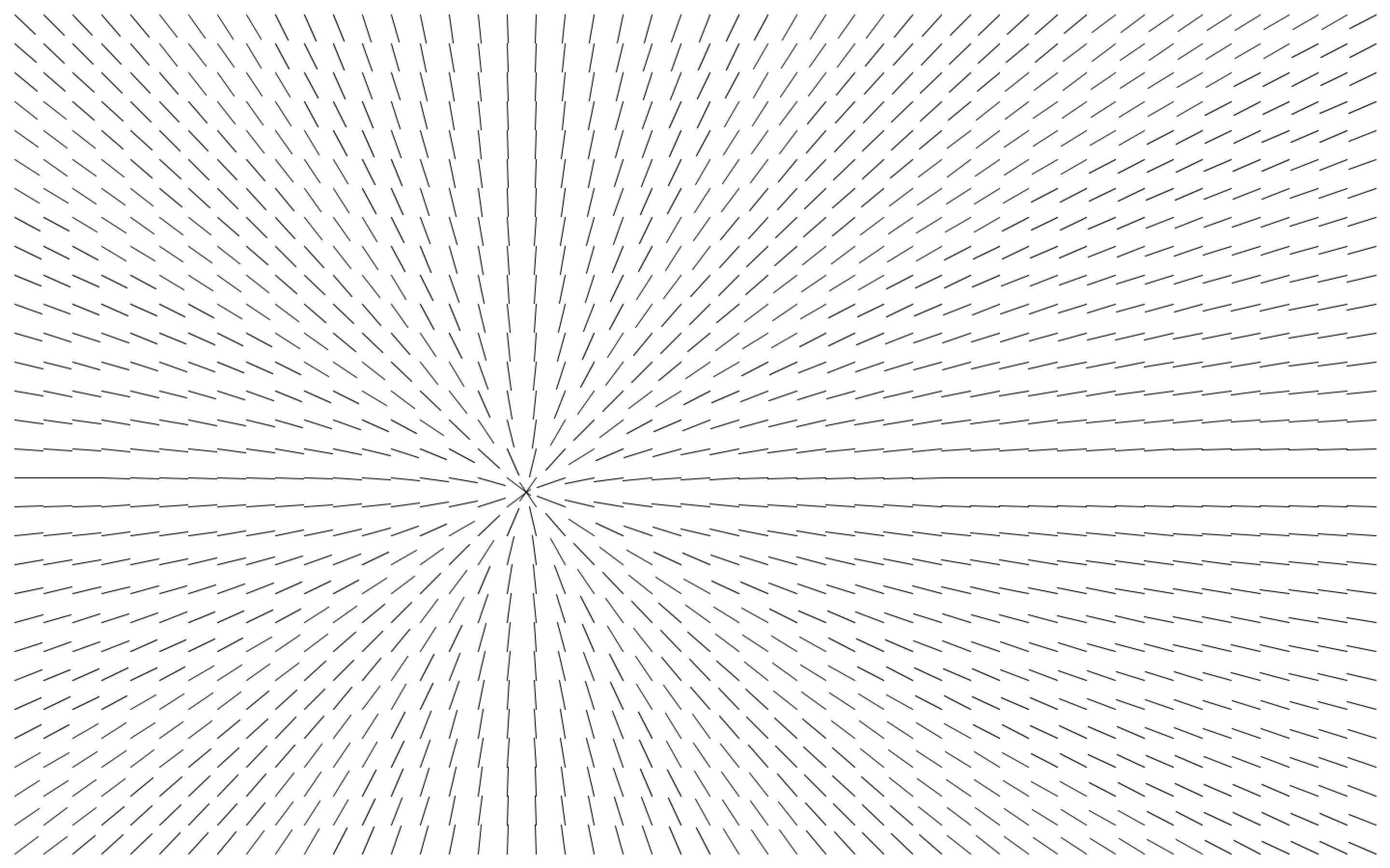
Code – lines pointing at mouse w/OOP

Main Sketch:

// declare an array of DirectionLines
DirectionLine lines[];

void setup() {
  fullScreen();

  //how long will each line be
  int lineLength = 30;

  //we can find out how many lines we will have 
  //by dividing width and height by the lineLength
  int w = width/lineLength;
  int h = height/lineLength;

  //initialize the array with number of total lines
  lines = new DirectionLine[w*h];

  //index to access each element of the array
  int i=0;
  //nested for loop, start at lineLength/2 to offset and center the lines on screen
  //increase each step through the loops by lineLength, to space the lines appropriately
  for (int y=lineLength/2; y<height; y+=lineLength) {
    for (int x=lineLength/2; x<width; x+=lineLength) {
      //access each DirectionLine in the way and create a new DirectionLine object
      //the x & y vairbales from the for loops give us the origin location of each line
      lines[i] = new DirectionLine(x, y, lineLength);
      //be sure to increase i
      i++;
    }
  }
}

void draw() {
  background(255);
  //just loop through all the lines and call run()
  for (int i=0; i<lines.length; i++) {
    lines[i].run();
  }
}

Class:

class DirectionLine {

  //variables
  float angle;
  float len;
  PVector origin;

  //constructor
  DirectionLine(float x, float y, float _len) {
    origin = new PVector(x, y);
    len = _len;
    angle=0;
  }

  //FUNCTIONS\\

  //update our angle based on the mouse position
  void update() {
    //turn the mouse into a pvector in order to use the pvector functions
    PVector destination = new PVector(mouseX, mouseY);
    //subtract the origin from the destination, this is our direction
    PVector direction = PVector.sub(destination, origin);
    //get the angle of the direction
    angle = direction.heading();
  }

  //draw the line
  void display() {
    pushMatrix();
    //translate and rotate the line based on the angle
    translate(origin.x, origin.y);
    rotate(angle);
    line(0, 0, len, 0);
    popMatrix();
  }

  //function to wrap up both update and display
  void run() {
    update();
    display();
  }
}

Code – Functions, Sine Ellipses, Noise Rectangles

Ellipses with Sine Modulation:

int numberEllipses = 32;
float segmentSize;
color c;

void setup() {
  size(640, 480);
  //divide the circle by number of ellipses we want to draw
  segmentSize = TWO_PI / numberEllipses;
  
  //show the use of function that returns an int
  println( multiplyBy2(100) );
  
  //set color to black to start
  c = color(0);
  noFill();
}

void draw() {
  background(255);
  stroke(c,100);
  drawCircles(width/2, height/2);
}

////////FUNCTIONS\\\\\\\\\

void keyPressed(){
  if (key==' '){
    c = color(random(255),random(255),random(255));
  }
}

//this is just for example and not used in the code
int multiplyBy2(int num) {
  return num * 2;
}

//draw one ellipse
void drawEllipse(int index) {
  //push and pop matrix to rotate this circle only
  pushMatrix();
  //change the rotation for each circle based on its index
  rotate(index*segmentSize);
  //the frequency is a scaled frameCount audjusted individually for each circle using i 
  float frequency = frameCount*.001*index;
  //the ampltiude adjusts a base height of 80 with sine
  float amplitude = 80 * sin(frameCount*.01);
  ellipse(0, 0, 170, sin(frequency) *amplitude );
  popMatrix();
}

//draw all the ellipses
void drawCircles(int x, int y) {
  pushMatrix();
  translate(x, y);
  for (int i = 0; i < numberEllipses; i++) {
    drawEllipse(i);
  }
  popMatrix();
}


Rectangles with Noise Modulation:

//width of each rectangle
int w = 8;
float speed = .01;
float granulation = .001;

void setup(){
  size(640, 480);
  rectMode(CENTER);
}

void draw(){
  background(255);
  //noise adjusting height of the rectangles
  for (int i=0; i<width; i+=w){
    //the slower the frequency the smoother the noise
    //use i to individuate each rectangle
    //scale i down some
    //then change over time with scaled down version of frameCount
    float frequency = (frameCount*speed) + (i*granulation);
    float amp = 100;
    //noise outputs between 0 & 1
    float adjustedNoise = noise(frequency)-.5; //make it so it gives us numbers between -.5 and .5
    float heightAdjustment = adjustedNoise * amp;
    rect(i+w/2, height*.25 + heightAdjustment, w, 100);
  }
  
  //noise adjusting rotation of the rectangles
  for (int i=0; i<width; i+=w){
    float frequency = (frameCount*speed) + (i*granulation);
    //map noise from 0-1 to 0-TWO_PI to get an angle around a circle
    float angle = map(noise(frequency), 0, 1, 0, TWO_PI);
    pushMatrix();
    translate(i+w/2, height-height*.25);
    rotate(angle);
    rect(0,0, w, 100);
    popMatrix();
  }
}


Code from Processing Intro

Colors, Shapes, & Interaction:

int rectX = 300;
int rectY = 100;
int rectWidth = 100;

color rectColor = color(255);
color circleColor = color(255);

color backgroundColor = color(255);


void setup() {
  size(640, 360);
}

void draw() {
  background(backgroundColor);
  

  if (mouseX > rectX // check if x is larger than our x starting point for our rectangle
    && mouseY > rectY // check if y is larger than our y starting point for our rectangle
    && (mouseX< rectX + rectWidth) // check if we're less than the horizontal boundary of our rect
    && (mouseY< rectY + rectWidth) //same as above but for the outer bound of the rect's height
    && mousePressed
    ) { 
    rectColor = color(255, 0, 0);
    circleColor = color(0, 255, 0);
  } else {
    rectColor = color(255);
    circleColor = color(255);
  }
  
  fill(rectColor);
  rect(rectX, rectY, rectWidth, rectWidth);
  
  fill(circleColor);
  ellipse(mouseX, mouseY, 50, 50);
}

void mousePressed(){
  backgroundColor= color(random(255), random(255), random(255));
}


Bouncing Balls:

int x, y, speedX, speedY;
float x2, y2, speedY2, gravity;

void setup(){
 size(640, 360); 
 x = width/2;
 y = 0;
 speedX = 9;
 speedY = 10;
 x2 = width/2;
 y2 = 0;
 speedY2 = 0;
 gravity = .5;
}

void draw(){
  background(255);
  //gravity bounce
  ellipse(x2, y2, 30, 30);
  y2 += speedY2;
  if (y2 > height || y2<0){
   speedY2 *= -.95; // speed = speed * -1;
  }
  speedY2 += gravity;
  y2 = constrain(y2, 0-1, height+1); // go a little outside for the constraints so that the flipping speed logci above works
  
  //whole screen bounce aaround ball
  ellipse(x, y, 30, 30);
  x += speedX;
  y += speedY; // y = y + speed;
  
  if (x > width || x<0){
   speedX *= -1; // speed = speed * -1;
  }
  
  if (y > height || y<0){
   speedY *= -1; // speed = speed * -1;
  }
}


Enclosure References

Box designer: http://boxdesigner.connectionlab.org/

Hollow project enclosure: http://makezine.com/projects/hollow-2×4-project-enclosure/

Examples from Aaron:

Makezine examples: http://makezine.com/slideshow/15-fantastic-project-enclosures/

Week 4 Circuits & Code – Analog Write, Servo, Buzzer, Tone Library


const int knobPin = A0;
const int ledPin = 3; // be sure to use a PWM pin!

void setup() {
  pinMode(ledPin, OUTPUT);
}

void loop() {
  // read the potentiometer value
  int knobValue = analogRead(knobPin);
  
  // analog write takes values between 0 and 255
  // map the knob value to be be between 0 and 255
  int brightness = map(knobValue,0,1023,0,255);

  // use the brightness value for the LED analog write
  analogWrite(ledPin, brightness);
}


#include <Servo.h>

Servo myServo;

const int knobPin = A0;

void setup() {
  // attach the servo to pin number 9
  myServo.attach(9);

}

void loop() {
  // read the potentiometer value
  int knobValue = analogRead(knobPin);
  
  // the servo only moves between 0 and 180
  // map the knob value to be be between 0 and 180
  int angle = map(knobValue,0,1023,0,180);

  // use the mapped angle to set the servo's rotation
  myServo.write(angle);

  // wait a very short bit for the servo to move to the location
  delay(15);
}


int buzzerPin = 4;

void setup() {
  pinMode(buzzerPin, OUTPUT);
}

void loop() {
  // arguments are pin, frequency, and duration
  tone(buzzerPin, 440, 200);
  // since the tone is lasting 200 milliseconds
  // delay for 400, so 200 on and then 200 off
  delay(400);

  // you could also do without the duration argument if you wanted a steady tone:
  //  tone(buzzerPin, 440);
}

Install the Tone Library by Brett Hagman to use more than one Buzzer:

// install the Tone Library by Brett Hagman to use multiple buzzers

#include <Tone.h>

// arrays to hold the note values
int notes[10] = {NOTE_C4, NOTE_D4, NOTE_E4, NOTE_F4, NOTE_G4, NOTE_A4, NOTE_B4, NOTE_C5, NOTE_D5, NOTE_E5};

Tone player0, player1;

// length in milliseconds
int duration = 250;

//variable to change note for player0
int whichNote = 0;

void setup() {
  // use pin 5 for buzzer 0
  player0.begin(5);
  // use pin 6 for buzzer 1
  player1.begin(6);
}

void loop() {
  // player0's notes change according to the number in whichNote
  player0.play(notes[whichNote], duration);

  // player1's note stays the same
  player1.play(notes[9], duration);

  // set whichNote to equal itself + 1
  // then modulo that number by 8, which creates a loop between 0-7 (8 digits)
  whichNote = (whichNote + 1) % 8; //do plus 1 to go up major scale, try others numbers like plus 3

  //wait for the notes to stop playing before going to the next note
  delay(duration);
}


Week 3 Circuits & Code – Analog Read and Blink Without Delay

Potentiometer:

Photoresistor:

const int ledPin = 2;
bool ledState = LOW;

// a really longer number with no + or - sign
unsigned long toggleTime = 0;
int triggerInterval = 500;

void setup() {
  pinMode(ledPin, OUTPUT);
  Serial.begin(9600);
}

void loop() {
  // read the analog input
  int knobValue = analogRead(A0);
  // map that input to a range appropriate for our use
  // in this case, we take the range of the photocell and map it to millis between 10 & 500
  // this is the blink interval for the LED
  triggerInterval = map(knobValue, 190, 860, 10, 500);

  // print out the original value and the mapped value on the same line
  Serial.print(knobValue);
  Serial.print(" ");
  Serial.println(triggerInterval);

  // if the current time (millis) is more than the exact time when we are supposed to toggle
  if (millis() > toggleTime) {
    // flip the LED to the opposite of what it was
    ledState = !ledState;
    // set the next time the LED should toggle
    // to the current time + whatever the blink interval amount of time is
    toggleTime = millis() + triggerInterval;
  }

  // turn the LED on or off based on the ledState vaviable
  digitalWrite(ledPin, ledState);
}


Week 2 – Digital Read/Write Circuit & Code

Digital Read a button on pin 2 and digital write an LED on pin 3:

Remember to include a 330 ohm resistor for the LED and a 10k ohm pull down resistor to ground for the button.

int buttonPin = 2;
int ledPin = 3;
int ledState = LOW;
int prevButtonState = LOW;

void setup() {
  // set pin modes
  pinMode(ledPin, OUTPUT);
  pinMode(buttonPin, INPUT);
  // needed in order to start serial communication
  Serial.begin(9600);
}

// PSUEDO CODE:
// check if button is currently pressed
// if button is pressed then check to see if it was pressed during the last frame too
// (we need to remember our button state)
// if button is bressed and previous button is not pressed then flip our LED state

 void loop() {
  // check to see what state our button is in, and store that information
  int currentButtonState = digitalRead(buttonPin);

  // if the button is currently being prssed down, AND during the last frame is wasn't pressed down
  if (currentButtonState == HIGH && prevButtonState == LOW) {
      // flip the LED state
      if (ledState == HIGH){
        ledState = LOW;
      } else if (ledState == LOW){
        ledState = HIGH;
      }
  }
  // if you want to print out the LED state
//  Serial.println(ledState);

  // set our LED to turn on and off according to our variable that we flip above
  digitalWrite(ledPin, ledState);

  //we need to remember the state of our button for the next time through LOOP
  prevButtonState = currentButtonState;
}