Final Project – Card detector and dealer

Idea:

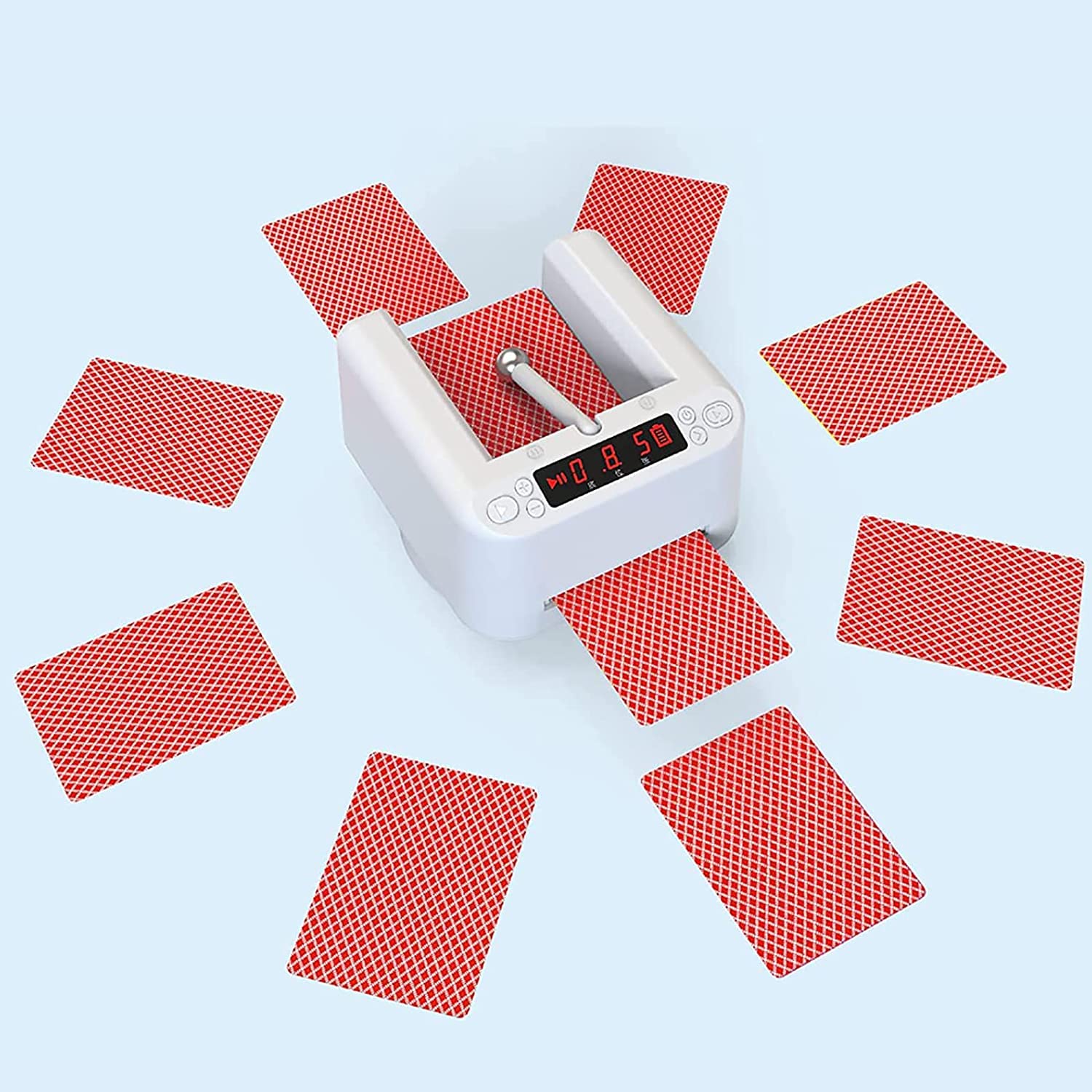
Starting from my very first Intro to IM assignment, I have been trying to combine the possibilities of Interactive Media and my passion for card magic. The initial idea for a project like this came to me as I remembered when once I saw an automatic card dealer that swiftly deals the appropriate number of cards to the selected number of players, and some models even shuffle the cards before dealing! Some of these models are sold commercially, but I wanted to go a step further – to try to make a card dealing machine that would help the user get a competitive edge over the other players – which is a natural extension to a device like this for a magician. Here is an example of one of those machines that are sold commercially.

Example of an automatic card dealer

Although there was a handful of card-dealer projects online, I could not find any project that would combine card detection and dealing except one, which was not feasible to make in the scope of the class. I had to find projects and information from all over the web and put them together into a cohesive whole, which was a challenging and a time-consuming task.

Physical Parts:

I found this video on YouTube that employs a close mechanism to what I wanted to create. Hence, I used some of the models that they created to 3D print a tray to hold the cards, a wheel that will dispense the cards, and the handle to hold the motor that the wheel is going to be attached to. I had to learn some use of a 3D modeling software to design my project accordingly, and I used FreeCAD to make all the necessary measurements. After some issues with 3D printing and with the help of Professor Aya the 3D models were successfully completed. I would some rubber string in the IM Lab that was the only fitting component that could be glued to the 3D printed wheel to dispense the cards. The rubber material was necessary to provide enough friction for the cards to be caught and moved.

The bottom platform I used is from this project (https://www.instructables.com/Rotating-Table-Tutorial-In-Progress/). The scale was modified to fit the project better.

After all the models were ready, I used the drills in the Lab to adjust the hole dimensions to fit every piece snugly. I have never worked with 3D printers before, therefore this part was quite challenging in terms of finding the right models and modifying them physically or digitally to make every piece work together. Gladly, everything was fitting in the end and it was time for time digital implementation.

Here is the final design of the device.

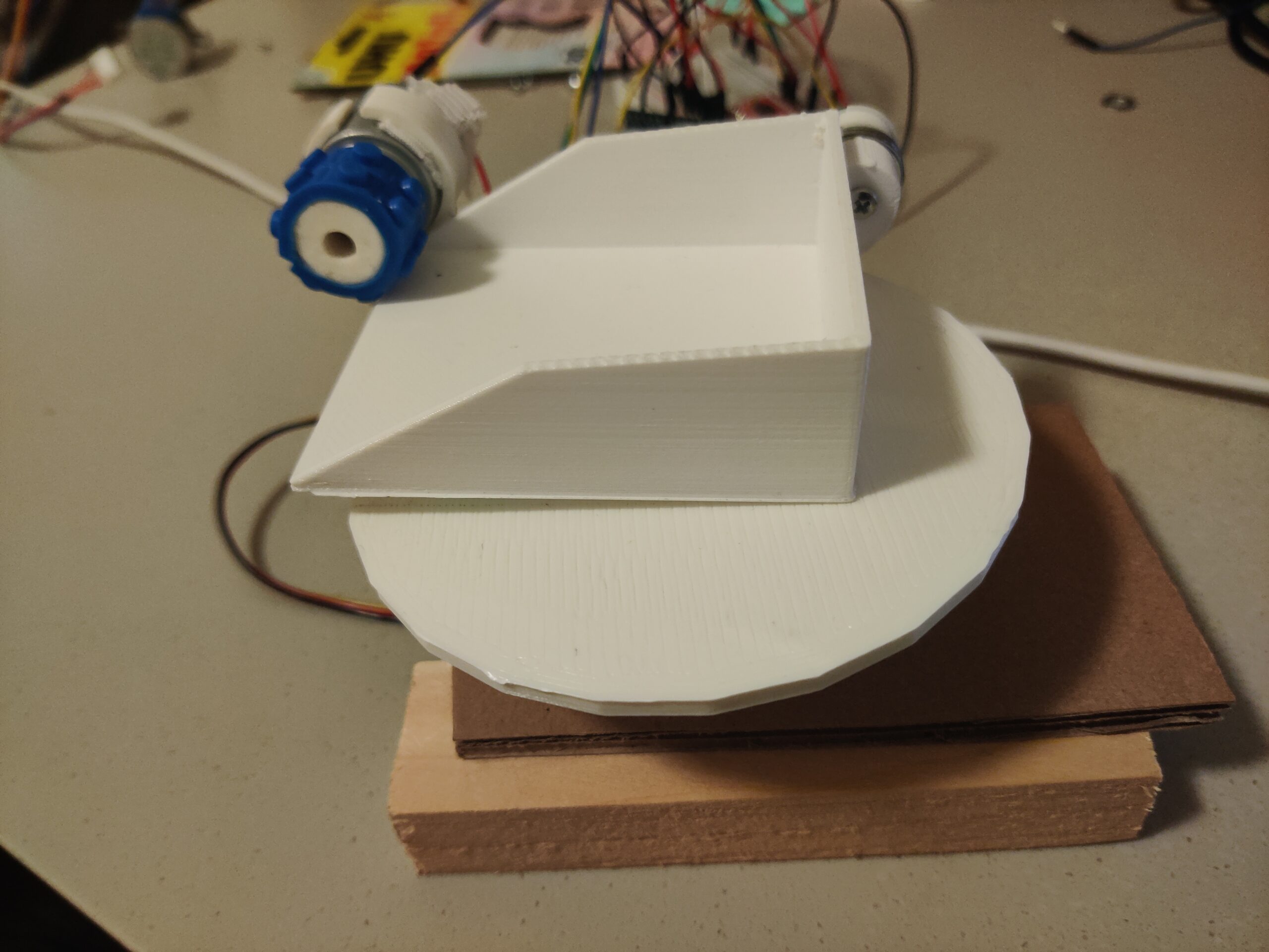
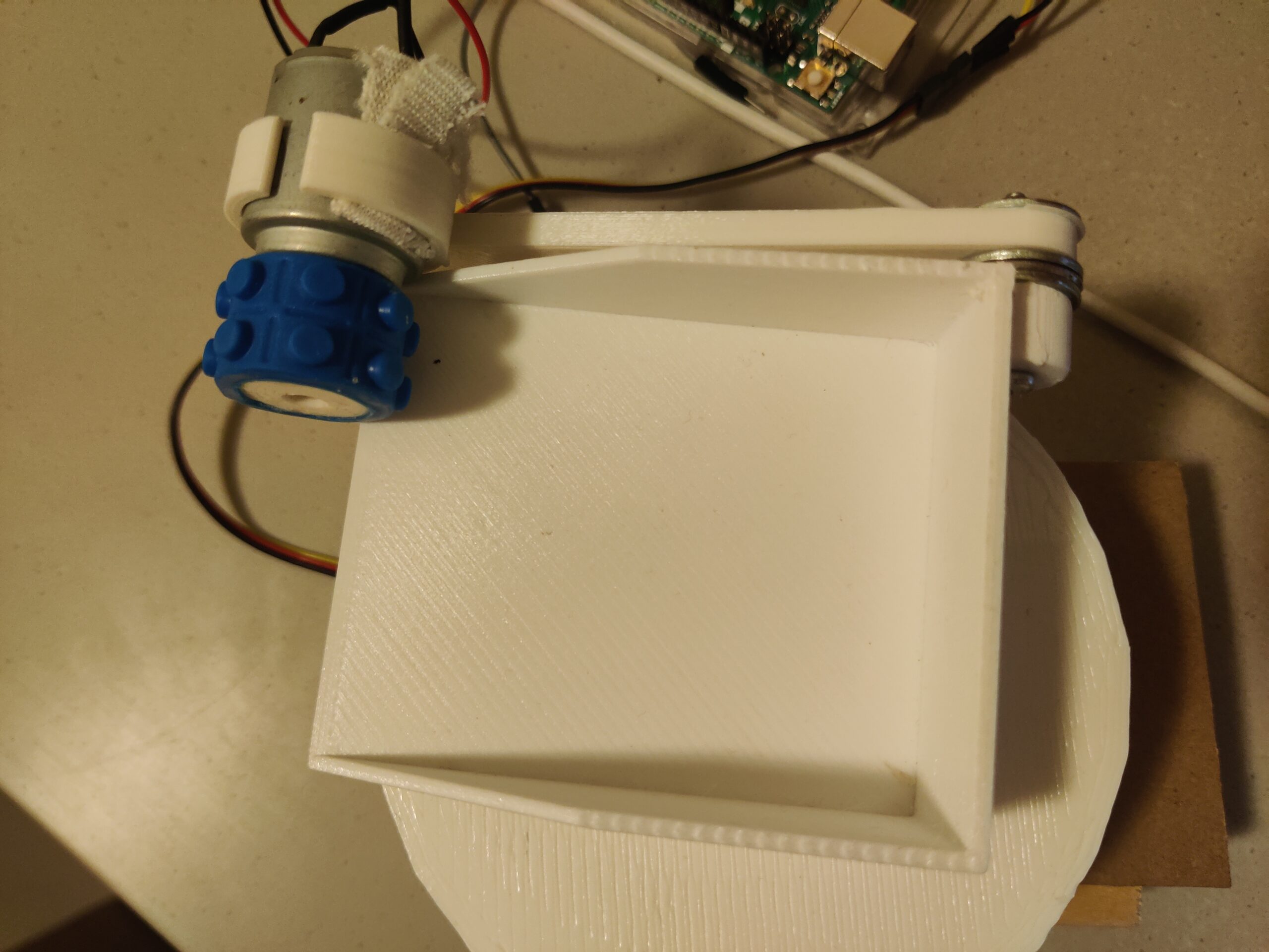
The servo motor for the base is fixed using cardboard and wooden blocks glued to the motor for stabilization. 

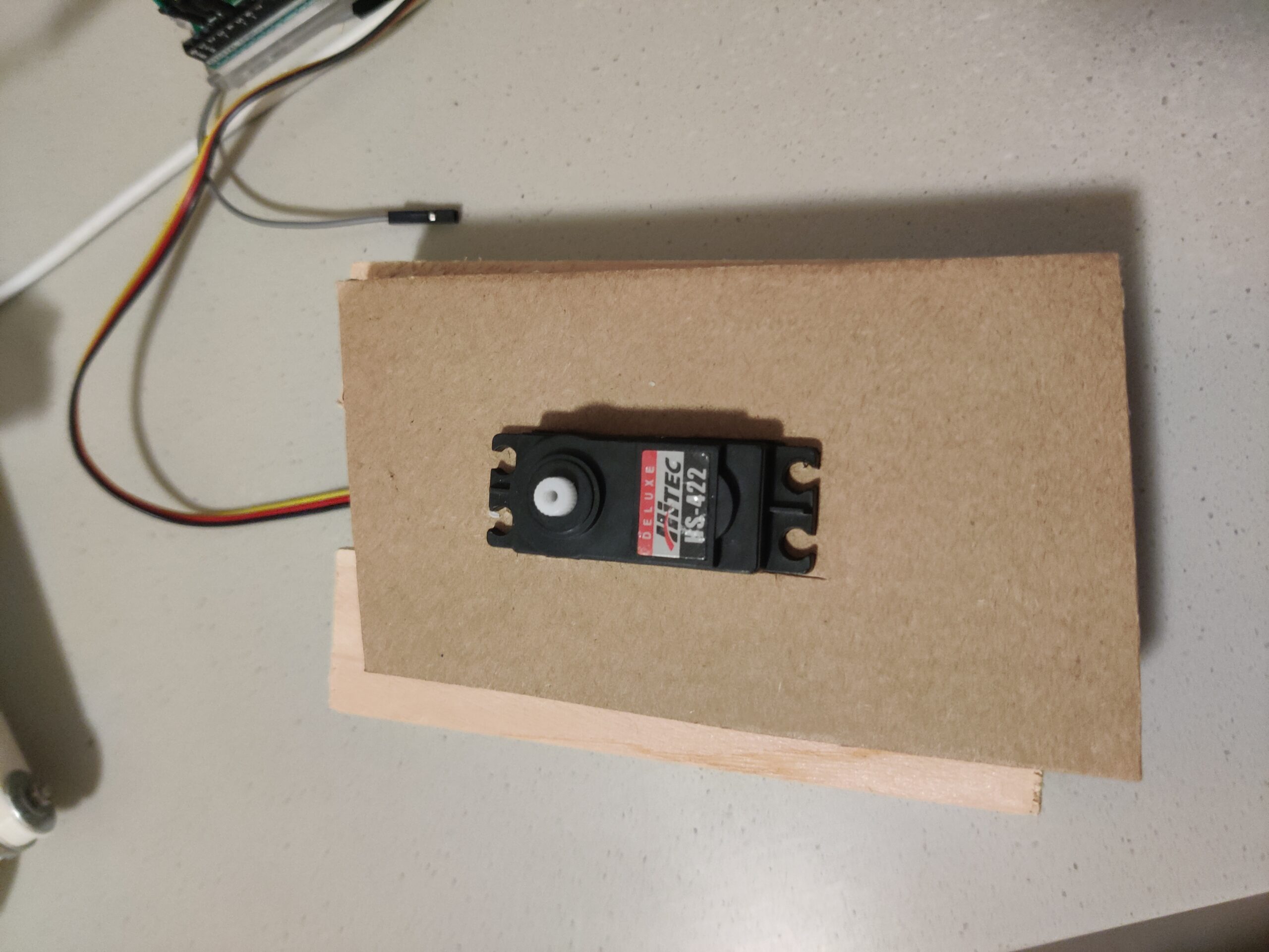
The detection model: This was undoubtedly the most challenging and novel part in this project. I went through a lot of options among training models myself and searching for pre0trained models until I found a pre-trained model on Roboflow for playing card detection (https://universe.roboflow.com/augmented-startups/playing-cards-ow27d/model/4). During this learning process I understood how to use pre-trained models and understood the process of training a model myself, but I am glad that I found a pre-trained one as training it myself would be a possible, but hugely a time-consuming process. Another major challenge arose during the deployment of the model on the website. I faced a lot of technical issues until making the model work on the website that I made for the project.

P5.js:

I went with a web-implementation route for the project as the Roboflow model did not work on the web editor for P5. There a couple major parts.

if (cardValue == choice && actionDone == 0) {
    found = 1;
    console.log("FOUND");
    sendToArduino();
    actionDone = 1;
  }

This part of the code is used to signal a write once to Arduino after the detection model sees the card chosen by the user.

function sendToArduino() {
  datatosend = 1 + "\n";
  writeSerial(datatosend);
  console.log("SENT TO ARDUINO: " + datatosend);
}

This function sends a true value to Arduino once the right card is detected.

var prediction = predictions[i];
    //console.log(prediction.class); 
    cardValue = prediction.class; 
    var x = prediction.bbox.x - prediction.bbox.width / 2;
    var y = prediction.bbox.y - prediction.bbox.height / 2;
    var width = prediction.bbox.width;
    var height = prediction.bbox.height;

This part of the code is getting the prediction of the model, which is a string value of two characters, the first one is the value of the card – either a number or a letter, the second one indicates the suit (Heart, Club, etc.). For instance, if the card chosen by the user is the Queen of Spades, the prediction model would detect the card and output “QS”, if the card is 7 of Hearts, the model would output “7H”. Because the user is choosing the card by inputting the string value into the website, they have to use the right syntax – two characters, no spaces, all capitalized.

Arduino:

The Arduino code is working with a DC motor, as a positional Servo motor did not have enough range to push the card over the edge of the deck to dispense it. The hardship here was to set exact timing and power to the motor to dispense one card only and not more. The motor also needed to push back the rest of the cards once the needed card is pushed out.

void launchCard(){
  analogWrite(pwmAPin, 200);
  digitalWrite(ain1Pin, HIGH);
  digitalWrite(ain2Pin, LOW);
  delay(140);
  digitalWrite(ain1Pin, LOW);
  digitalWrite(ain2Pin, LOW);
  delay(1000);
  analogWrite(pwmAPin, 200);
  digitalWrite(ain1Pin, LOW);
  digitalWrite(ain2Pin, HIGH);
  delay(300);
  digitalWrite(ain1Pin, LOW);
  digitalWrite(ain2Pin, LOW);
  delay(1000);
}

This is the function that does exactly that.

while (Serial.available()) {
     digitalWrite(LED_BUILTIN, HIGH); // led on while receiving data 
     int found = Serial.parseInt();
      if (Serial.read() == '\n') {
       if (found == 1){
        base.write(120);
        delay(1000);
        launchCard();
        base.write(60);
        delay(1000);
       }
       found = 0;

       }
  }

This part of the code is in the main loop function. Once the user’s card is found, the Servo motor rotates the tray to a different angle, dispenses the user’s card, then comes back and continues to dispense the rest of the cards.

Final Thoughts:

The goal that was set in the beginning of the project was met: a card dispensing machine that can also modify the dealing by detecting cards. The expansions on this idea can be multiple in the realm of card handling. As a magician, I can use this accessory to enrich my tricks to make the machine the machine pick the right selection by the user.

Using only the Arduino part, the machine can work as a normal dealing machine if the deck is put face-down in the machine and 2-5 people are playing a game and need cards to be dealt to them. The device can also be used to sort cards with little modification to the code. In addition to that, if the detection is to be used in an actual game where cards are being dealt face-down, a simple solution would be to cover the device from the top and sides, attach a platform in front of the tray so that the cards are dealt on top of it one by one, then simply rotate the platform 180 degrees to drop the card face down on the table. That way the dealing would seem fair, but the camera can still see the cards from the top and make manipulations accordingly.

The most challenging part of the project was finding and learning how to use a machine learning model and integrating it into my program. However, after a long time of trying to figure it out, I learned the necessary skills of using it which will undoubtedly help me in my future projects.

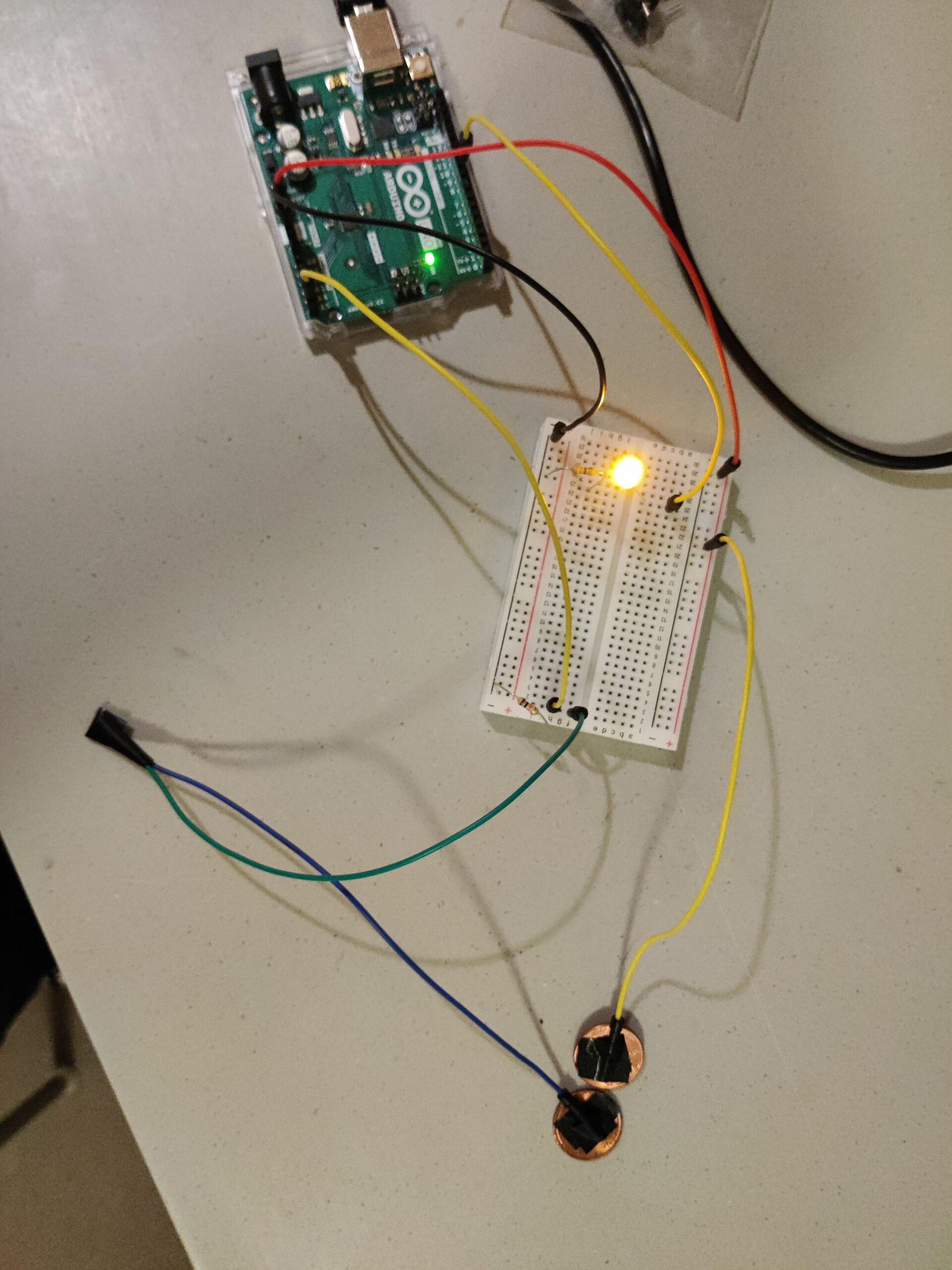
I also faced some technical difficulties which I became aware of late in the project, i. e. the motor that I used had faulty wiring and was giving me inconsistent results when I thought the code of the motor was incorrect. I had to hold the wire with one of my hands during the showcase, however I was somewhat glad to find that the main issue was easily fixable with a new pair of wires. In the video below, the 3 of Clubs did not jump out at the end like the other cards because the base turned and weakened the wire connection by displacing the handle with the motor.

Overall, I reached the goal that I had set in the conception of the project idea, and I think the project was a success overall.


Week 12 Assignment

Assignment 1:

For this assignment, it displays an ellipse whose horizontal position is controlled by a potentiometer connected to an Arduino board. When the space bar is pressed, it establishes a serial connection. The Arduino continuously reads the potentiometer value and sends it to the P5.js sketch via serial communication, allowing real-time adjustment of the ellipse’s position.

P5 code:

let ellipseHorizental;
function setup() {
  createCanvas(640, 480);
  textSize(18);
  ellipseHorizental = width/2; 
}
function draw() {
  background(220);
  // Draw ellipse with width based on potentiometer value
  fill("green");
  ellipse(ellipseHorizental, height / 2, 100, 150);
  if (!serialActive) {
    text("Press Space Bar to select Serial Port", 20, 30);
  } else {
    text("Connected", 20, 30);
    // Print the current potentiometer value
    text('Potentiometer Value = ' + str(ellipseHorizental), 20, 50);
  }
}
function keyPressed() {
  if (key == " ") {
    setUpSerial();
  }
}
function readSerial(data) {
  if (data != null) {
    // convert the string to a number using int()
    let fromArduino = split(trim(data), ",");
    // Map the potentiometer value to the ellipse width
    ellipseHorizental = map(int(fromArduino[0]), 0, 1023, 0, 640); 
  }
}

Arduino code:

const int potPin = A0;  // Analog pin connected to the potentiometer
void setup() {
  Serial.begin(9600);
}
void loop() {
    int potValue = analogRead(potPin);  // Read the value from the potentiometer
      // Send the potentiometer value to p5.js
      Serial.println(potValue);
}

Assignment 2:

For assignment 2 it establishes communication between a P5.js sketch and an Arduino board for controlling LED brightness. The P5.js sketch allows users to adjust brightness by dragging the mouse horizontally, with instructions displayed when the serial connection is active. The Arduino board continuously waits for serial data from the P5.js sketch, adjusting the LED brightness accordingly. During setup, a handshake process is initiated, blinking the built-in LED while waiting for serial data.

P5 code:

let brightness = 0; //variable for brightness control

function setup()
{
createCanvas(400, 400); //create canvas
}

function textDisplay() //display text in the starting
{
text("PRESS SPACE TO START SERIAL PORT", width/2 - 109, height/2 - 5);
}

function draw()
{

background(220); //grey background

if (serialActive) //if serial is active
{
text("connected", width/2 - 27, height/2 - 5); //tell the user that it is connected
text("Drag the mouse horizontally to change brighthess", width/2 - 130, height/2 + 15); //give instructions on how to control brightness
}
else
{
textDisplay(); //display instructions on how to start serial is not active
}
  
if (mouseX >= 0 && mouseX<=10){
  brightness = 0;
}
else if (mouseX >= 3 && mouseX<=width/5){
  brightness = 51;
}
else if(mouseX >= width/5 && mouseX<=2*width/5){
  brightness = 102;
}
else if(mouseX >= 2*width/5 && mouseX<=3*width/5){
  brightness = 153;
}
else if(mouseX >= 3*width/5 && mouseX<=4*width/5){
  brightness = 204;
}
else if (mouseX>=4*width/5){
  brightness = 255;
}
else{
  brightness = 0;
}
  
}

function keyPressed() //built in function
{
if (key == " ") //if space is pressed then
{
setUpSerial(); //setup the serial
}


}

//callback function
function readSerial(data)
{
let sendToArduino = brightness + "\n"; //add the next line to dimness counter
writeSerial(sendToArduino); //write serial and send to arduino
}

Arduino code:

int LED = 5; // Digital pin connected to the LED
void setup() {
  Serial.begin(9600);
  pinMode(LED_BUILTIN, OUTPUT);
  pinMode(LED, OUTPUT);
  // start the handshake
  while (Serial.available() <= 0) {
    digitalWrite(LED_BUILTIN, HIGH); // on/blink while waiting for serial data
    Serial.println("0");             // send a starting message
    delay(300);                       // wait 1/3 second
    digitalWrite(LED_BUILTIN, LOW);
    delay(50);
  }
}
void loop() {
  // wait for data from p5 before doing something
  while (Serial.available()) {
    digitalWrite(LED_BUILTIN, HIGH); // led on while receiving data
    int brightnessValue = Serial.parseInt();
    if (Serial.read() == '\n') {
      delay(5);
      Serial.println(brightnessValue);
    }
    analogWrite(LED, brightnessValue);
    digitalWrite(LED_BUILTIN, LOW);
  }
}

Assignment 3:

For this assignment, we tried to establish communication between a P5.js sketch and an Arduino board (bi-directional). The P5.js sketch simulates a ball’s motion affected by wind and gravity, with its behavior controlled by sensor data received from the Arduino. The Arduino reads data from an ultrasonic sensor to determine distance, sending LED control signals back to the P5.js sketch based on the received distance data, influencing wind direction and LED turning on.

P5 code:

//declare variables
let velocity;
let gravity;
let position;
let acceleration;
let wind;
let drag = 0.99;
let mass = 50;
let LEDvalue = 1401;
let goRight = 0;
let goLeft = 0;
let first

function setup() {
createCanvas(1000, 360); //create canvas
noFill();
position = createVector(width/2, 0);
velocity = createVector(0,0);
acceleration = createVector(0,0);
gravity = createVector(0, 0.5*mass);
wind = createVector(0,0);
}

function textDisplay()
{
text("PRESS SPACE TO START SERIAL PORT", width/2 - 109, height/2 - 5); //display the appropriate text in the start
}

function draw() {
background(255);
if (serialActive) //if the serial is active
{
applyForce(wind);
applyForce(gravity);
velocity.add(acceleration);
velocity.mult(drag);
position.add(velocity);
acceleration.mult(0);
ellipse(position.x,position.y,mass,mass);
if (position.y > height-mass/2) //if the ball touches the bottom
{
velocity.y *= -0.9; // A little dampening when hitting the bottom
position.y = height-mass/2;
LEDvalue = 1401; //take LED value to be 1401 because we dont want the value (1) to be lurking in the serial and then affecting the wind values

}
else
{
LEDvalue = 1400; //when the LED is off
}

}
else
{
fill(0);
textDisplay();
}
}

function applyForce(force){
// Newton's 2nd law: F = M * A
// or A = F / M
let f = p5.Vector.div(force, mass);
acceleration.add(f);
}

function keyPressed(){
if (key==' '){ //if space is pressed, then serial is set up
setUpSerial();
}

if (keyCode == DOWN_ARROW) //if down arrow is pressed
{
//mass etc is changed
mass=random(15,80);
position.y=-mass;
velocity.mult(0);
}
}

function readSerial(data) //call back function
{
let sendToArduino = LEDvalue + "\n"; //sends value of LED to Arduino with \n added
writeSerial(sendToArduino); //write to Arduino

if (data != null) //if the data is not null and something is received
{
console.log(data);
if (data > 1450) //if the distance is greater than 1450, then
{
wind.x = 1; //the ball/wind goes right
}
else if (data < 1350) //if the distance is less than 1350
{
wind.x = -1; //the ball/wind goes left
}
}
}


Arduino code:

//declare variables
const int LED_PIN = 4;
int LEDvalue = 0; //will contain whether or not the LED should be on or off
int distance = 0; //will contain the distance by ultrasonic sensor
const int pingPin = 2; //Trigger Pin of Ultrasonic Sensor
const int echoPin = 3; //Echo Pin of Ultrasonic Sensor

void setup()
{
Serial.begin(9600); // Start serial communication at 9600 baud

pinMode(LED_PIN, OUTPUT); //pin mode is output

//Set the ultrasonic sensor pins as output and input respectively
pinMode(pingPin, OUTPUT);
pinMode(echoPin, INPUT);

while (Serial.available() <= 0)
{
Serial.println(1400); //connection establishment. 1400 so that the wind values do not change
}
}

void loop()
{
//wait for p5js
while (Serial.available())
{
sensorReading(); //reads data from the sensor

LEDvalue = Serial.parseInt(); //parsing from the serial written data from p5js

if (LEDvalue == 1400) //if the LED value is 1400
{
digitalWrite(LED_PIN, LOW); //then turn off the LED
}
else if (LEDvalue == 1401) //if the LED value is 1401
{
digitalWrite(LED_PIN, HIGH); //then turn on the LED
}
}
}

//Function to read the ultrasonic sensor and measure distance
void sensorReading()
{
//Send a short low pulse
digitalWrite(pingPin, LOW);
delay(2); //delay to avoid complications
digitalWrite(pingPin, HIGH); //sends a high pulse for 10 microseconds
delay(10);
digitalWrite(pingPin, LOW); //turn off the ping pin
distance = pulseIn(echoPin, HIGH); //Measure the duration of the ultrasonic pulse and calculate the distance
Serial.println(distance); //print the serial from distance
}

Musical Instrument

For this week’s assignment, we made a simple musical instrument using the Arduino. It is more similar to DJ equipment than a traditional musical instrument – slowing down the music or speeding it up, switching between different speed quickly to add dynamics to the music, and, of course, flashy lights, which will make or break the party. As part of the assignment, we used the button switch as the digital input and the potentiometer as the analog input. The Arduino plays a melody through a buzzer, and  4 LEDs light up in correspondence with the melody. By pressing the button, you can play the melody. The potentiometer allows you to control the length or duration of the melody.

Components Used

  • Arduino Uno
  • Breadboard
  • Jumper wires
  • Button
  • Potentiometer
  • LED (4 of different colors)
  • Buzzer
  • Resistors (330 ohms x 2)


#include "pitches.h"

#define BUZZER_PIN 12
#define ANALOG_PIN A0
#define RED_PIN 11
#define GREEN_PIN 10
#define BLUE_PIN 9
#define YELLOW_PIN 6
#define DIGITAL_PIN A1

int melody[] = {
  NOTE_B4, NOTE_B5, NOTE_FS5, NOTE_DS5,
  NOTE_B5, NOTE_FS5, NOTE_DS5, NOTE_C5,
  NOTE_C6, NOTE_G6, NOTE_E6, NOTE_C6, NOTE_G6, NOTE_E6,

  NOTE_B4, NOTE_B5, NOTE_FS5, NOTE_DS5, NOTE_B5,
  NOTE_FS5, NOTE_DS5, NOTE_DS5, NOTE_E5, NOTE_F5,
  NOTE_F5, NOTE_FS5, NOTE_G5, NOTE_G5, NOTE_GS5, NOTE_A5, NOTE_B5
};

int durations[] = {
  16, 16, 16, 16,
  32, 16, 8, 16,
  16, 16, 16, 32, 16, 8,

  16, 16, 16, 16, 32,
  16, 8, 32, 32, 32,
  32, 32, 32, 32, 32, 16, 8
};

bool isPlaying = false;

void setup() {
  pinMode(BUZZER_PIN, OUTPUT);
  pinMode(DIGITAL_PIN, INPUT_PULLUP); 
  pinMode(RED_PIN, OUTPUT);
  pinMode(GREEN_PIN, OUTPUT);
  pinMode(BLUE_PIN, OUTPUT);
  pinMode(YELLOW_PIN, OUTPUT);
}


void playMelodyWithLEDs() {
  int size = sizeof(durations) / sizeof(int);

  for (int note = 0; note < size; note++) {
    if (!isPlaying) return;

    int duration = 1000 / durations[note];
    tone(BUZZER_PIN, melody[note], duration);

    int sensorValue = analogRead(ANALOG_PIN);
    float speed = map(sensorValue, 0, 1023, 1.3, 6.0); 

    int pauseBetweenNotes = duration * speed;

    int ledPattern[] = { RED_PIN, GREEN_PIN, BLUE_PIN, YELLOW_PIN };
    int ledIndex = note % 4;
    digitalWrite(ledPattern[ledIndex], HIGH);
    delay(pauseBetweenNotes);
    digitalWrite(ledPattern[ledIndex], LOW);

    noTone(BUZZER_PIN);

    delay(50); 
  }
}

void loop() {
  if (digitalRead(DIGITAL_PIN) == LOW) {
    isPlaying = false;
    digitalWrite(RED_PIN, LOW);
    digitalWrite(GREEN_PIN, LOW);
    digitalWrite(BLUE_PIN, LOW);
    digitalWrite(YELLOW_PIN, LOW);
  } else {
    isPlaying = true;
    playMelodyWithLEDs();
  }
  delay(200);
}

The map() function is a hidden gem in this code. It’s a versatile function that remaps a range of values from one scale to another. In our case, the potentiometer reading (analog input) ranges from 0 to 1023. We use map() to translate these values to a range of speeds between 1.3 and 6.0. This allows the potentiometer to control the tempo of the melody playback.

The loop() function continuously checks the button state. If the button is pressed (digitalRead(DIGITAL_PIN) == LOW), the isPlaying flag is set to false, effectively stopping the melody. Additionally, the LED lighting is turned off (digitalWrite(RED_PIN, LOW), etc.). When the button is not pressed (digitalRead(DIGITAL_PIN) == HIGH), the isPlaying flag is set to true, and the playMelodyWithLEDs() function runs.

As we were integrating the LEDs with the melody, we struggled a bit. Initially, the LED light-up function was different, and it had a separate delay() for the individual LED to match with the melody. It did not work as expected. We realized after playing a note if we move to the separate LED function and delay there, the melody becomes very slow due to using 2 separate delays. So, we removed the LED function and used the same delay() for both the notes and LEDs.

Reading Reflection – Week #11

This week’s reading reflection was about “A Brief Rant on the Future of Interaction Design” by Bret Victor. I agree with the notion of tapping into the potential of human body and its capabilities. The technology nowadays heavily relies on vision and touch and the use of our hands, but I like the idea of offering more comprehensive technology that goes beyond simple touch and sliding your hand across a screen.

It could be argued that there are voice controls that could be especially useful for user with visual impairments, but they are far from the usefulness of vision and hands. A next step in voice controlled software could be achieved by the use of LLMs and Artificial Intelligence, but the author talks about the incompleteness of audio controls and its limitations in the follow-up article about his rant. Although the touch technology has its constraints, it is getting better by involving the pressure neurons in our hands, like incorporating 3d touch sensors in our screens which makes the situation a little better, but still far from the ideal the author talks about.

The author does not offer solutions for the problems of current technology, but advocates for a more thoughtful use of the capabilities of our hands. deviating from the topic of hands, I was thinking of going a step further, but not necessarily in the direction of using our bogy. We are somewhat stepping over the solutions tat could be offered by our body and going directly into the brain with “Neuralink”. Brain chips and their future would not require detailed technology that uses our bodies, as the controls would be directly supplied by our brain. However, I still think that using the untapped potential of just our hands would be a great step towards much more interactivity in human technology.

Reading Reflection – Week #10

I found the readings for today quite engaging in the sense that the first reading “Making Interactive Art: Set the Stage, Then Shut Up and Listen” offers vision for how interactivity should be executed by artists, and the second reading gives us widespread examples of such interactivity in the world of physical computing.

Firstly, I would like to address the points that resonated with me. I agree that exploring the interactive artwork by yourself is a better experience than being guided and directed along the way of that exploration. That could give audience a sense of emotional connection to the work, as the more modes and options of interaction there are, the more the artwork could “feel like home” for the individuals in the audience, hence leaving the audience and the artwork face-to-face is a great way of fostering emotional connection.

However, I do not agree with the distinction that the author makes between interactive artwork and other artwork. Many books, paintings are left for interpretation, which, I would argue, carries a sense of interactivity with the artwork, with the ideas, the perception of those ideas between audience members. So, I would not rush to call traditionally non-interactive artwork a “statement” or just an “expression”, as the author mentions. Vice versa, what we call interactive artwork can be understood solely as an expression in some cases, therefore the definition of “interactive artwork” is blurry and needs refinement in order to be categorized as needed to be left interpretation.

As a tangent to the last point, I, personally, do not appreciate the firm stances of guarding the intention of the author from audiences’ interpretation. I understand the value it can provide, as outlined in the beginning of this reflection, but I appreciate getting a chance for a glimpse of what was going on in the author’s mind while creating the artwork, as the process of creation could be as valuable as the creation itself, if not more.

Potentiometer Switch

I came up with the idea of this assignment while playing around with the potentiometer. It has a wide range of values it can provide and I wanted to utilize the potential of its variability and precision.

There are 4 LEDs – red, yellow, green and blue – that light up as the values generated by the variable resistor change. The potentiometer is the analog sensor here, but provides functionality of both an analog and a digital sensor. The purely digital sensor here is the green button.

The potentiometer values are supplied to the digital output pins and control the brightness of the LEDs. The value range of the potentiometer is also split into 4 equal segments, so that each LED only has a quarter of the full range of brightness it can take. The splitting also allows to switch the LED as the value changes, meaning for (0, 256] range of the potentiometer reading, one LED lights up with (0, 1/4] of its brightness range. Same logic applies to the other LEDs in a successive fashion.

The green button  (digital sensor) allows to change the sequence of LEDs that light up with certain values of the potentiometer. For instance, if initially the red LED has the lowest quarter of values, the switch sets that lowest range to the next LED in succession, which would be the yellow one, and every LED gets the position of the next one, hence in this example the red one would get the highest range of values and be the brightest if turned on. The video of how the system works is attached below.

The main code responsible for the button and the value switches is provided below. The relatively challenging part was figuring out a way to make the switch between what values which LED gets, and I ended up with an array structure for efficiency.

if (buttonState == HIGH){
    if (swapped == 0){
    switchState += 1;
    switchState = switchState % 4;
    }
    swapped = 1;
  }
  else{
    swapped = 0;
  }

  if (sensorValue > 0 && sensorValue <= 256){
    analogWrite(leds[switchState], sensorValue/4);
    digitalWrite(leds[(switchState+1)%4], LOW);
    digitalWrite(leds[(switchState+2)%4], LOW);
    digitalWrite(leds[(switchState+3)%4], LOW);
    //speed = 2000;
  }
  else if(sensorValue > 256 && sensorValue <= 512){
    digitalWrite(leds[switchState], LOW);
    analogWrite(leds[(switchState+1)%4], sensorValue/4);
    digitalWrite(leds[(switchState+2)%4], LOW);
    digitalWrite(leds[(switchState+3)%4], LOW);
    //speed = 1000;
  }
  else if(sensorValue > 512 && sensorValue <= 768){
    digitalWrite(leds[switchState], LOW);
    digitalWrite(leds[(switchState+1)%4], LOW);
    analogWrite(leds[(switchState+2)%4], sensorValue/4);
    digitalWrite(leds[(switchState+3)%4], LOW);
    //speed = 500;
  }
  else if(sensorValue > 768 && sensorValue <= 1023){
    digitalWrite(leds[switchState], LOW);
    digitalWrite(leds[(switchState+1)%4], LOW);
    digitalWrite(leds[(switchState+2)%4], LOW);
    analogWrite(leds[(switchState+3)%4], sensorValue/4);
    //speed = 250;
  }
  else{
    digitalWrite(red, LOW);
    digitalWrite(yellow, LOW);
    digitalWrite(green, LOW);
    digitalWrite(blue, LOW);
    //speed = 0;
  }

For improvements, I could add more variability into what the button does, possibly incorporate flickering rate for different potentiometer readings to make the transitions more clear. I also could optimize the code and make it more reusable so that when new functionality or LEDs are added, it does not take much code to incorporate.

Unusual Switch

For the project, I was walking around my room and looking for creative ways to create a switch. Finally, I found two American pennies which are made from zinc and are coated with copper, both of which are good conductive materials. Then, I realized I could make a switch that works when the coins touch. Wires are taped to the coins so that when the coins touch, the circuit closes and lights up the yellow LED. I connected the green and blue wires together to extend the reach of the coins. The idea is similar to Carrom – the coin that has an extended reach has to be flung into the other coin which will be relatively stationary. The setup can be seen below.

Next, I write some code for the Arduino, so that when they touch, the LED stays lit for 3 seconds so that the contact is captured and a hit or miss can be seen clearly.

void setup() {
  // put your setup code here, to run once:
  pinMode(9, OUTPUT);
  pinMode(A5, INPUT);
}

void loop() {
  // put your main code here, to run repeatedly:
  int switchState = digitalRead(A5);

  if (switchState == HIGH){
    digitalWrite(9, HIGH);
    delay(3000);
  }
  else{
    digitalWrite(9, LOW);
  }
}

Reading Reflection – Week#8

Both of the readings for this week have similarities and differences with each other, but one common thread among these readings that I tried to follow and extract was the role of human subjectivity in design. The first reading introduces psychological concepts in the form of affect and analyzes how they interact with design. The second reading shows the importance of it more subtly, by showing how a hazardous error was found by a kid playing around with the keyboard, and the same error was committed by an astronaut that was believed to be exceptionally professional. Unfortunately, nobody is perfect, and every human holds a different set of characteristics and, therefore, has a different perspective on the world and the tools they use. Hence, the one idea I would connect these readings with is the idea of personalization in design. Just like the three teapots in Norman’s text, different design has different form and functionality and can suit different people to accomplish a task. Even the same person in different moods or environments could desire a different design. If this idea is paired with the “beauty is subjective” discussion, we can see how personalization of design is important from Norman’s ideas about attractive things working better. As much as we like to think of ourselves as rational and intelligent creatures, humans are emotional at core and this should be reflected in good design, incorporating emotional choices along with functional choices.

Midterm Project Beatly

My midterm project is centered around an idea of a digital drum kit. As a drummer, I sometimes want to test new beats and patterns when I am not around a physical kit, and in such times I like to use the “musicca” website(https://www.musicca.com/drums), and this is the website that I got the inspiration for my project from. Each sound on the drum kit is tied to a specific key and the digital drum kit is played just like a physical one would, by combining sequences of keys corresponding to the notes. I have found all the essential sounds for each key from the website “freesound” (https://freesound.org/), including the cheering sound.
Next, I made the project more visual so that besides the audio feedback, users can also get a visual feedback corresponding to the sound that has been played. For that I have implemented circle waves of different color, each corresponding to a certain drum/cymbal, that arise from the center of the drum/cymbal that has been played and propagate across the screen. To mark a milestone in the user’s drumming session, after a certain number of notes played, a crowd cheers for you and colorful confetti pop up. This was the hardest part of the project as besides using the relevant classes and finding information on how to implement it, I had to make sure the timing and duration of the confetti was precise and simultaneous with the cheer sound. The implementation of that tricky part is the following.

if (counter%60 == 0 && counter !=0) { //60 bets till cheer
isDisplaying = 1; //bool for confetti
start = millis(); //timer start
interval = 0; //should be 5 seconds
isCheering = 1; //cheer sound bool
if (isCheering == 1 && cheer.isPlaying()==false){
cheer.play();
isCheering = 0; //so it does not loop again
print("isCheering is:" + isCheering);
}
}
if (isDisplaying == 1){
for (let i = 0; i < confetti.length; i++) {
if (interval < 5000){ confetti[i].confettiDisplay(); finish = millis(); interval = finish - start; } else{ isDisplaying = 0; }

if (confetti[i].y > height) {
confetti[i] = new Confetti(random(0, width), random(-height, 0), random(-1, 1)); //generate confetti instead of the ones that have disappeared
print("in the if");
}
}

The starting page contains instructions to which key produces which sound, but it is always fun to experiment if you do not know the names of the drums and cymbals! For the main page, I have cut the background off of the drum image and placed it on a stage surrounded by people – a choice to justify the cheering and confetti. Here is the photo of the background stage I used.

To play the drums, the user clicks on the “Start” button and after the user is done he can click “Restart”, so that the new user can play the drums. Restarting simply erases the counter for how many notes have been played and places the user back on the intro screen. I chose not to include any background music as the rhythm of the background music would interfere with and limit what the user wants to play. To enter or exit fullscreen, the user needs to press the “F” key.
In the future, I would like to implement more artistic waves that propogate from the circles or have a music choice that the user can play into. For improvements, the fullscreen mode needs to be improved to fit the actual full size of the screen.

Midterm Project Progress

My midterm project will center around an idea of a digital drum kit. As a drummer, I sometimes want to test new beats and patterns when I am not around a physical kit, and in such times I like to use the “musicca” website(https://www.musicca.com/drums), and this is the website that I got the inspiration for my project from. Each sound on the drum kit is tied to a specific key and the digital drum kit is played just like a physical one would, by combining sequences of keys corresponding to the notes. Accurate and user-friendly implementation of the sounds and keys will be a major part of the project. I will use the image below for a drum kit and I will label each drum/cymbal with the corresponding key so that new users can easily navigate and learn in a matter of seconds. I have taken this image from “musicca”, only editing out the drums sticks that are present on the website as I think my implementation does not require drum sticks, because of a different visual feedback that is discussed below.
Additionally, I have found all the essential sounds for each key from the website “freesound” (https://freesound.org/).
Next, I wish to make the project more visual so that besides the audio feedback, users can also get a visual feedback corresponding to the sound that has been played. For that I will implement circle waves that arise from the center of the drum/cymbal that has been played and will propagate across the screen. This is going to be the most challenging part of the project, and I am thinking about implementing collision effect for those waves, but I will decide on it later depending on the visual effects created. I am still searching for ideas to implement besides the circle waves that will make appealing visuals, but so far I sympathize with this implementation the most.
There are 2 classes for the project so far. A class for drums, each object being a different drum or cymbal, and a class for the waves, each object being the wave tied to a certain drum/cymbal.
There will be a button at the bottom of the drum kit image, suggesting the users to start a new session if the previous user is done, and the functionality of button is simply to remove the existing waves from the screen, everything else does leave a residual effect from the previous to the new user.