Final Project (+ User Testing) – Stefania Petre

Concept:

For this final project, I envisioned entering a universe where art and technology collide to create something genuinely unique. I wanted to make it easy for people who have never drawn before to experience it for the first time.

Imagine an interactive space where art and technology merge, transforming bodily movements into a rainbow of colours on a digital canvas. My initiative encourages individuals to exhibit their ideas through motion. They use a paintbrush attached to an Arduino to navigate a symphony of colourful ellipses. This is more than simply an artwork; it’s an experience that captures the essence of movement and transforms it into a personalised digital masterpiece.

Arduino Part:

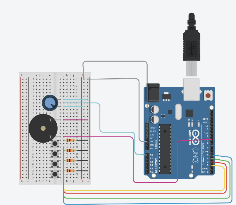
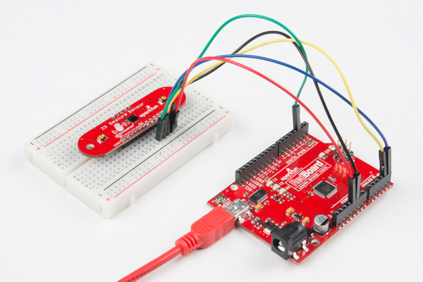
The foundation of the interaction is the Arduino Uno, on which I worked with a ZX Distance and Gesture Sensor. The sensor is adept at monitoring the paintbrush’s proximity as well as the artist’s minor hand gestures. To be honest, installation was rather simple, but the sensor itself was not as powerful as planned.

Input: Proximity data and gesture commands from the ZX Sensor.
Output: Serial communication to relay the sensor data to the computer running the p5.js sketch.
Data to p5.js: Real-time Z-axis data for proximity (distance of the hand or brush from the sensor) and X-axis data for lateral movement, along with gesture detections (swipes, taps).
From p5.js: Instructions may be sent back to calibrate gesture sensitivity or toggle the sensor’s active state.

P5.js Part:

On the digital front, p5.js will serve as the canvas and palette, with dynamic and malleable capabilities. It will translate the incoming data from the Arduino into a series of colours and movements on the screen.

Receiving Data: Interpreting proximity and gesture data from the Arduino.
Processing Movements: Real-time mapping of hand movements to colour strokes and splashes with varied intensity and spread on a digital canvas.
Visual Feedback: Dynamic visual changes that reflect the flow and dance of the user’s motions.
To Arduino: Signals for modifying the ZX Sensor parameters in response to real-time performance and user feedback.

Graphics Used:

Gesture: Swipe Left / Right, Tap

Visuals: Dynamic shapes, colors, and brush strokes based on movement data.

Development and User Testing
The ZX Distance and Gesture Sensor has now been integrated with Arduino, and the immediate goal is to ensure that data flows smoothly into the p5.js programme. By the time user testing begins next week, the system should respond to hand motions by presenting relevant visual modifications on the screen.

User Testing Objectives:

  • Assess how natural and fulfilling it is to paint in midair.
  • Ensure responsiveness and accuracy of gesture detection.
  • Gather feedback from participants regarding the ease of use and satisfaction with the interactive art experience.

User Testing Techniques:

    • Record interactions on video to analyze gesture accuracy and timing.

How it Works:

  1. Arduino Setup: Connect Arduino to the ZX Sensor and establish serial communication with p5.js.
  2. Gesture Detection: The Arduino reads gestures and proximity data and sends this information to the p5.js sketch.
  3. Canvas Response: p5.js interprets the data and creates a dynamic visual display that reflects the gestures and brush movements.
  4. Feedback Loop: p5.js sends calibration data back to Arduino to adjust the sensor settings if necessary.

Code 
Arduino Code Example:

#include <Wire.h>
#include <ZX_Sensor.h>

// Constants
const int ZX_ADDR = 0x10;  // ZX Sensor I2C address

// Global Variables
ZX_Sensor zx_sensor = ZX_Sensor(ZX_ADDR);
uint8_t x_pos;
uint8_t z_pos;
uint8_t handPresent = false;

void setup() {

  Serial.begin(9600);
  
  zx_sensor.init();

 
   while (Serial.available() <= 0) {
 
    Serial.println("0,0,0"); // send a starting message
 
    delay(50);
  }
}

void loop() {
  
  // If there is position data available, read and print it
  if ( zx_sensor.positionAvailable() ) {
    uint8_t x = zx_sensor.readX();
    if ( x != ZX_ERROR ) {
      x_pos=x;
    }
    uint8_t z = zx_sensor.readZ();
    if ( z != ZX_ERROR ) {
      z_pos=z;
    }
    handPresent=true;
  } else {
    handPresent=false;
  }
  
   while (Serial.available()) {
   

    int  inbyte = Serial.parseInt();
    if (Serial.read() == '\n') {
     
      Serial.print(x_pos);
      Serial.print(',');
      Serial.print(z_pos);
      Serial.print(',');
      Serial.println(handPresent);
    }
  }

}


P5 Code:

// FINAL PROJECT BY STEFANIA PETRE
// FOR INTRO TO IM

let img;
let brushSize = 19;
let colorHue = 0;
let previousX = 0,
  previousY = 0;
let xPos = 0;
let zPos = 0;
let smoothedX = 0;
let handPresent = 0;
let showDrawing = false;
let startButton; 
let mappedX = 0;
let mappedZ = 0;

function preload() {
  img = loadImage("start.webp");
}

function setup() {
  createCanvas(640, 480);
  colorMode(HSB, 360, 100, 100, 100);
  textSize(18);

  // Set up the start button
  startButton = createButton("Get Creative!");
  startButton.position(290, 175); 
  startButton.mousePressed(startDrawing);

  
  let fullscreenButton = createButton("Fullscreen");
  fullscreenButton.position(10, 10); 
  fullscreenButton.mousePressed(toggleFullScreen);

  // Set the initial hue
  colorHue = random(360);
}

function draw() {
  if (!showDrawing) {
    background(img);
  } else {
    if (!serialActive) {
      background(0);
      fill(255);
      //text("Press the 'Get Creative!' button to start drawing", 20, 30);
    } else {
      if (handPresent == 1) {
        // Adjust mapping ranges according to your actual data
        mappedX = map(xPos, 180, 40, 0, width); 
        mappedZ = map(zPos, 240, 25, 0, height); 
       
        mappedX = constrain(mappedX, 0, width);
        mappedZ = constrain(mappedZ, 0, height);

        let weight = 10; // Adjust as needed
        let strokeColor = color(colorHue % 360, 100, 100);

        stroke(strokeColor);
        strokeWeight(weight);
        ellipse(mappedX, mappedZ, weight * 2, weight * 2);

        previousX = mappedX;
        previousY = mappedZ;
      }

      colorHue += 2;

      noStroke();
      fill(0, 0, 0.000000000000005, 1);
      rect(0, 0, width, height);
    }
  }
}

function startDrawing() {
  showDrawing = true; 
  startButton.hide(); 
  setUpSerial();
}

function toggleFullScreen() {
  let fs = fullscreen();
  fullscreen(!fs);
  resizeCanvas(windowWidth, windowHeight);
  startButton.position(windowWidth / 2 - 40, windowHeight / 2 - 30);
}

function readSerial(data) {
  if (data != null) {
    let fromArduino = split(trim(data), ",");
    if (fromArduino.length == 3) {
      xPos = int(fromArduino[0]);
      zPos = int(fromArduino[1]);
      handPresent = int(fromArduino[2]);
    }
    let sendToArduino = 0 + "\n";
    writeSerial(sendToArduino);
  }
}

function keyPressed() {
  if (key == " ") {
    setUpSerial();
  }
}

function windowResized() {
  resizeCanvas(windowWidth, windowHeight);
}

Final thoughts: 

Even though the project was not exactly how I have pictured it at the beginning, it still worked out well. People at the showcase liked it and everything worked for 3 hours and I am happy that I have chosen this path.

Signing Off,

Stefania Petre

Assignment #12 – Stefania Petre (with Amal and Afra)

Initial connection and wiring from the schematic:

Exercise 1:

This was probably the easiest exercise, we just had to edit the code that was in the Week 12 Lecture Notes.

P5.js Code:

let potentiometer = 0;

function setup() {
  createCanvas(640, 480);
  textSize(18);
}

function draw() {
  background(255);
 
  if (!serialActive) {
    text("Press Space Bar to select Serial Port", 20, 30);
  } else {
    text("Connected", 20, 30);
    text('Potentiometer = ' + potentiometer, 20, 70);
  }

 
  let ellipseX = map(potentiometer, 0, 1023, 0, width);
  fill(0);
  ellipse(ellipseX, height / 2, 50, 50);

function keyPressed() {
  if (key === ' ') {
    setUpSerial();
  }
}

function readSerial(data) {
  if (data != null) {
    let trimmedData = trim(data);
    if (!isNaN(trimmedData)) {
      potentiometer = int(trimmedData);
    }
  }
}

Arduino Code:

void setup() {
  Serial.begin(9600);

  pinMode(LED_BUILTIN, OUTPUT);
  digitalWrite(LED_BUILTIN, HIGH);
  delay(200);
  digitalWrite(LED_BUILTIN, LOW);
}

void loop() {
  int sensorValue = analogRead(A1);

  Serial.println(sensorValue);

  delay(10);
}

Design Meets Disability Reading Reflection – Stefania Petre

I found “Designer Meets Disability” to be really meaningful. Not only was it a thought-provoking read, but it also made me consider my own design methods and prejudices. I was forced to reconsider what good design actually entails after reading this book, particularly in light of accessibility.

I remember a project I worked on where I had to use p5.js to create an interactive experience. At first, all I concentrated on was making things look good and work well enough for the average user. But reading this book made me see how important it is to take into account the people who might interact with my work in a different way. This realisation completely changed the way I approached design.

Especially inspirational was the notion that disability may spur innovation rather than hinder it. It has forced me to take a more expansive view, realising that include accessibility from the outset benefits everyone by enhancing both the design process and the final product, rather than just being about ethics or compliance.

I’m more dedicated than ever to making sure that my designs are not just aesthetically pleasing and useful, but also widely accessible as I work on my interactive media projects. Regardless of a person’s ability, I aim to create experiences that they can all enjoy and profit from.

Project Proposal – Stefania Petre

Hey there!

For this final, I have imagined stepping into a world where art and technology intertwine to create something truly special.

Envision an interactive space where art and technology fuse, transforming physical gestures into a cascade of colors on a digital canvas. My project is an invitation to express creativity through motion, as participants use a paintbrush to navigate a symphony of shapes and hues. This is not just an artwork but an experience that captures the essence of movement and translates it into a personalized digital masterpiece.

Arduino Part:

At the interaction’s core lies the Arduino Uno, paired with a ZX Distance and Gesture Sensor. The sensor is adept at tracking the proximity of the paintbrush and the subtle hand gestures of the artist.

  • Input: Proximity data and gesture commands from the ZX Sensor.
  • Output: Serial communication to relay the sensor data to the computer running the P5 sketch.
  • Data to P5: Real-time Z-axis data for proximity (distance of the hand or brush from the sensor) and X-axis data for lateral movement, along with gesture detections (swipes, taps).
  • From P5: Instructions may be sent back to calibrate gesture sensitivity or toggle the sensor’s active state.

P5JS Part:

On the digital front, P5 will act as the canvas and palette, responsive and mutable. It will process the incoming data from the Arduino, converting it into an array of colors and movements on the screen.

  • Receiving Data: Interpretation of proximity and gesture data from the Arduino.
  • Processing Movements: Real-time mapping of hand movements to strokes and splashes of color, varying in intensity and spread on the digital canvas.
  • Visual Feedback: Dynamic visual changes to represent the flow and dance of the user’s movements.
  • To Arduino: Signals for adjusting the ZX Sensor settings based on real-time performance and user experience feedback.

So far, this is how the painting should look like:


Development and User Testing:

The ZX Distance and Gesture Sensor is now integrated with Arduino. The creation of a smooth data flow to the P5 programme is the urgent objective. The system should react to hand motions by displaying appropriate visual changes on the screen by the time of user testing the following week. Assessing user interaction—specifically, how natural and fulfilling it is to paint in midair—will be largely dependent on this initial prototype. The documentation of user testing will involve multiple techniques such as gathering feedback from participants, recording interactions on video, and analysing the responsiveness of the system.


Week 11 – Reading Response

Victor urges designers to defy convention and rethink how we engage with technology through his criticism.

Victor’s initial outburst functions as a wake-up call, stressing how crucial quick feedback loops and user-friendly interfaces are to creating meaningful user experiences. He highlights how technology can empower people and foster creativity, and he pushes for a move towards direct manipulation and user-centric design.

There is a wide range of viewpoints from the design world in the replies to Victor’s questions. While some share his views and support his vision for the direction of interface design, others present opposing arguments and voice legitimate doubts about the viability and practicality of his suggestions.

In my opinion, Victor makes strong arguments. I really like how he emphasises user empowerment and the transformative power of interactive technologies. His appeal for creativity is in line with my own conviction that technology has the ability to improve human experiences and encourage meaningful interaction.

I do, however, recognize the difficulties of turning creative concepts into workable solutions. Victor makes some insightful and thought-provoking suggestions, but putting them into practice in real-world settings necessitates giving considerable thought to user requirements, technology limitations, and wider societal ramifications.

Week 11- Stefania Petre (with Afra and Amal)

🌟 Inspiration: 

Music possesses a remarkable capacity to bridge cultural and linguistic divides and unite individuals from diverse backgrounds. Motivated by the notion of promoting interactive experiences and democratizing music creation, we set out to build a one-of-a-kind musical instrument out of buttons and Arduino. Our intention was to enable people to use sound as a creative medium for self-expression, irrespective of their experience with music. We chose the piano as our main inspiration because we could recreate the chords using buttons.


💡 Process:


Using Arduino Uno we wired up buttons to serve as interactive triggers for different musical notes. Each button was assigned a specific pitch or sound, allowing users to create melodies by pressing combinations of buttons. We leveraged our programming skills to code the logic behind the instrument, ensuring seamless functionality and an intuitive user interface.


🚀 Difficulties: 


Although our journey was exciting and innovative, there were certain difficulties. A major challenge we encountered was guaranteeing the reliability and consistency of button pushes. We have to use precise calibration and filtering techniques to get beyond problems like noise interference and debounce.


There were additional difficulties in creating an intuitive user interface. To ensure that users could simply grasp how to interact with the instrument while still having the freedom to explore and experiment with various musical compositions, we had to find a balance between simplicity and utility.

Our arduino illustration:

The code:

onst int speakerPin = 9;  // Speaker connected to pin 9
int buttonPins[] = {2, 3, 4, 5};  // Button pins for C, D, E, F
int notes[] = {262, 294, 330, 349};  // Frequencies for C4, D4, E4, F4

void setup() {
  // Set up each button pin as an input with pull-up resistors
  for (int i = 0; i < 4; i++) {
    pinMode(buttonPins[i], INPUT_PULLUP);
  }
  // Set the speaker pin as an output
  pinMode(speakerPin, OUTPUT);
}

void loop() {
  // Check each button and play the corresponding note
  for (int i = 0; i < 4; i++) {
    if (digitalRead(buttonPins[i]) == LOW) {  // Check if button is pressed
      tone(speakerPin, notes[i]);  // Play the corresponding note
      delay(200);  // A short delay to help debounce the button
      while (digitalRead(buttonPins[i]) == LOW);  // Wait for the button to be released
      noTone(speakerPin);  // Stop playing the note
    }
  }
}

The video:


Week #10 Assignment

Concept: 
For this assignment, I decided to implement the things that I have already learned in regards to the ultrasonic sensor and add the button. I wanted to see how far I can go with my knowledge.
Implementation:
The implementation was pretty easy, as I have used the previous assignment as an example. I just added the button and changed the code and voila!
End result:

Code:

//Intro to IM - Stefania Petre
// Define LED pins
int ledPin[3] = {8};

// Define Ultrasonic sensor pins
const int trigPin = 2; // or any other unused digital pin
const int echoPin = 3; // or any other unused digital pin

const int buttonPin = 13;
int buttonState = HIGH;
int lastButtonState = HIGH;
long lastDebounceTime = 0;
long debounceDelay = 50;
int pushCounter = 0;
int numberOfLED = 3;

void setup() {
  pinMode(buttonPin, INPUT);
  digitalWrite(buttonPin, HIGH); // Activate internal pull-up resistor
  
  // Set up LED pins
  for (int i = 0; i < numberOfLED; i++) {
    pinMode(ledPin[i], OUTPUT);
  }
  
  // Set up Ultrasonic sensor pins
  pinMode(trigPin, OUTPUT); // Sets the trigPin as an OUTPUT
  pinMode(echoPin, INPUT);  // Sets the echoPin as an INPUT
}

void loop() {
  int reading = digitalRead(buttonPin);

  // Check if the button state has changed
  if (reading != lastButtonState) {
    // Reset the debounce timer
    lastDebounceTime = millis();
  }

  // Check if the debounce delay has passed
  if ((millis() - lastDebounceTime) > debounceDelay) {
    // If the button state has changed, update the button state
    if (reading != buttonState) {
      buttonState = reading;

      // If the button state is LOW (pressed), increment pushCounter
      if (buttonState == LOW) {
        pushCounter++;
      }
    }
  }

  // Update the last button state
  lastButtonState = reading;

  // Turn off LED
  for (int i = 0; i < numberOfLED; i++) {
    digitalWrite(ledPin[i], LOW);
  }

  // Perform Ultrasonic sensor reading
  long duration, distance;
  digitalWrite(trigPin, LOW);
  delayMicroseconds(2);
  digitalWrite(trigPin, HIGH);
  delayMicroseconds(10);
  digitalWrite(trigPin, LOW);
  duration = pulseIn(echoPin, HIGH);
  distance = (duration * 0.0343) / 2; // Calculate distance in cm

  // Perform actions based on distance measured
  if (distance < 30) {
    // Turn on LED
    digitalWrite(ledPin[0], HIGH);
 

  // Delay before next iteration
  delay(100); // Adjust as needed
}

Comments:

Even though I got it to work, I still would have liked it to change colors depending on the distance from the sensor. I will try to implement that next time!

Week #10 – Reading Response

Among the first reading’s example, Fields of Grass attracted my curiosity the most. Thinking about it, I feel that the sensors could be organized in various ways so that the output changes dependent on not only the position of the hand, but also to the pressure applied. Designing a virtual world where the terrain alters depending on how firmly you push your hand is pretty cool. Delicate touches could disclose hidden passageways or generate peaceful sounds, while larger pressing might unleash bolder graphics or more dramatic effects. Beyond pressure, the sensor array might be adjusted to respond to additional hand interactions. An teaching tool might be created out of the project at a museum. Using pressure or movement to control elements like water or sunshine, visitors may “grow” a variety of virtual plants by placing their hands in specific locations. Physical therapy might benefit from the apps as well, as the virtual environment could react to particular hand gestures or muscle control, offering a visually appealing means of monitoring improvement.

In addition, I thought the author’s recommendation to “shut up and listen”—that is, to pay great attention to how people engage with and respond to the work—was extremely applicable to interface design in general, not just in artistic contexts. By seeing where our works fall short in the future, we may learn so much. Thus, it’s crucial to remain receptive to such criticism in order to improve the work. I also asked my friends to play games with me and give me constructive critique for my midterm.


Week 9 – Unusual Switch

Ever since professor Sherwood told us about this assignment, I have started to think about how can I use my feet in order to make the LED light go on.

At first, I discovered that I need to use a sensor, which I found in the kit. Then, with a little inspiration from one of my favorite bands ever, Queen, I started to think about interactive ways to make this happen.

This was the result (excuse my PJs and slippers I was sick) :

At first, my right leg is right in front of the sensor. After the first few kicks, I move the right leg right next to the sensor, so that the LED light will turn off.

This was the code that I used:

//declaring the pins of the sensors
const int trigPin = 12;
const int echoPin = 13;
long duration; 
int distance;

//declaring the rgb led
int rgb_r = 8;
int rgb_b = 7;
int rgb_g = 4;

void setup() {
  // put your setup code here, to run once:
  pinMode(echoPin, INPUT);
  pinMode(trigPin, OUTPUT);
  pinMode(rgb_r, OUTPUT);
  pinMode(rgb_b, OUTPUT);
  pinMode(rgb_g, OUTPUT);
  Serial.begin(9600);
}

void loop() {
  // put your main code here, to run repeatedly:
  digitalWrite(trigPin, LOW);
  delayMicroseconds(2);

  digitalWrite(trigPin, HIGH);
  delayMicroseconds(10);
  digitalWrite(trigPin, LOW);

  duration = pulseIn(echoPin, HIGH);
  distance = duration * 0.034 / 2;

  // We check the measured distance and control the RGB LED depending on it
  // If distance between 20-50 cm, LED is blue
    analogWrite(rgb_r, 0);
    analogWrite(rgb_g, 0);
    analogWrite(rgb_b, 255);
    Serial.println("Led is blue!");

  }

  delay(1000);
  Serial.print("distance = ");
  Serial.print(distance);
  Serial.print("\n");
  delay(1000);
}

It would have been complete if I added the hand claps with the kicks for sound purposes but I did not want to be taxed for that in regards to my grade 🙂 .

Overall, it was fun to make. The sensor is not that strong so in the future I would like to use something stronger maybe. Also, this can become an actual project and I could make it so that the color of the led would change when your feet have different positions.

Reading Response Week 8a – Stefania Petre

Before purchasing my current laptop, I spoke with a computer expert about which gadget I should purchase. He informed me that if I want it look nice, I should purchase a MacBook, but if I care about the “inside” of it, I should get something different. This is the same idea that the author discusses in this reading. Sometimes we choose things just for aesthetic purposes.

I think we can all remember the dispute between Android and iOS users. Even today I see people arguing about who can take the prettier picture of the moon and often times the android users are better at it. However, iOS still wins with most sales. Why? Because they have a prettier design .

This concept of design is called “Attractiveness Bias” which means that people tend to assume that people/objects who are physically attractive/ appealing, based on social beauty standards, also possess other desirable  traits.

Overall, I believe that design is truly a “make or breake” factor that influences the user experience a lot. I think that creators should think about that in advance in order for it to be successfull.

For me, as a design oriented person, I will always choose the aesthetically pleasing products.


(here I attached two pictures: the first one is an Asus ZenBook and the other one is a MacBook Pro)