Saiki Final Project: Motion Tracking CCTV Camera

My final project is a motion tracking CCTV camera that utilizes poseNet. The basic idea is to use poseNet to locate a person on the screen, and then send that data to a 3D printed CCTV camera mounted on top of a servo motor. By mapping the location data to the angles of the servo motor, it creates the illusion that the CCTV camera is following the person. In addition to the camera tracking, I also wanted to create a motion detecting p5 interface. After watching coding train tutorials on this effect, I discovered a method that uses pixel array data to isolate the moving person from the background, which I found really cool.

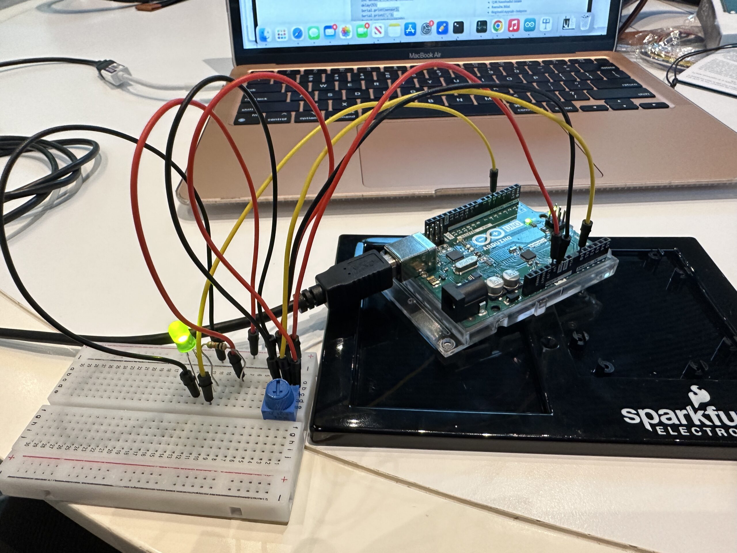
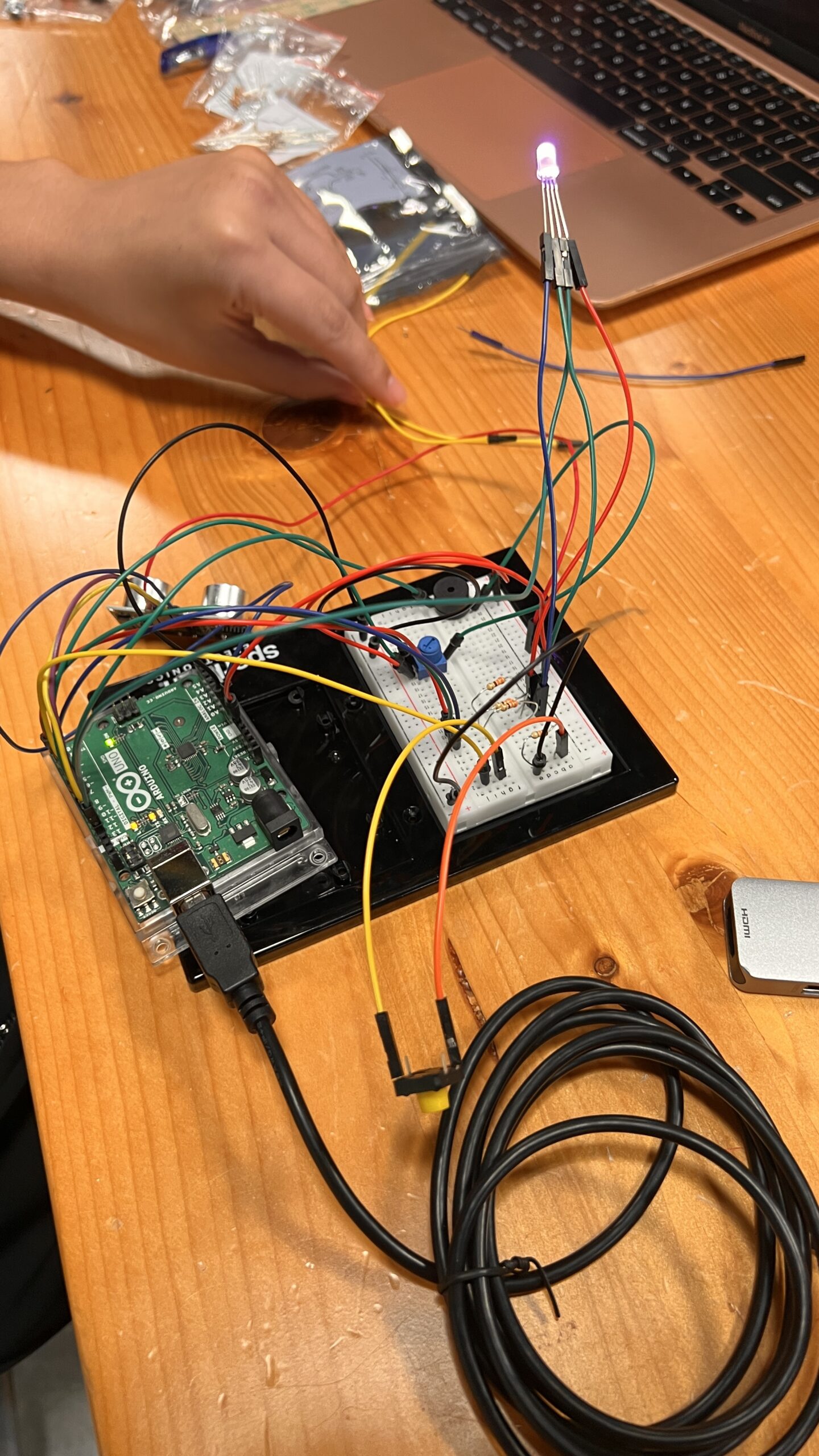
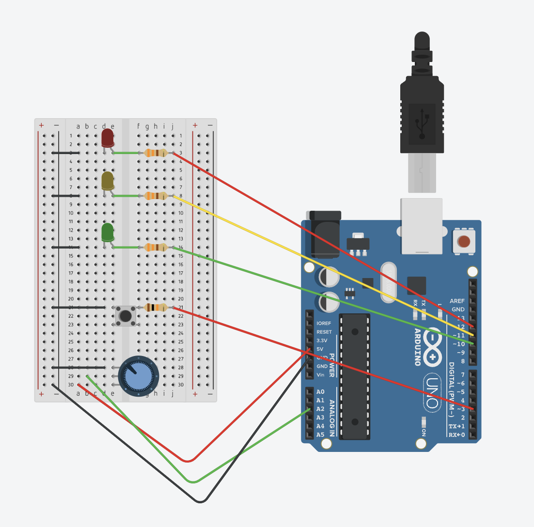
A large part of my process involved testing whether the servo-poseNet idea would work or not, and my draft of the final project documents this discovery. For the final project, I had several challenges ahead of me, including creating the p5 interface, figuring out the CCTV camera, and building a base for the camera and motor.


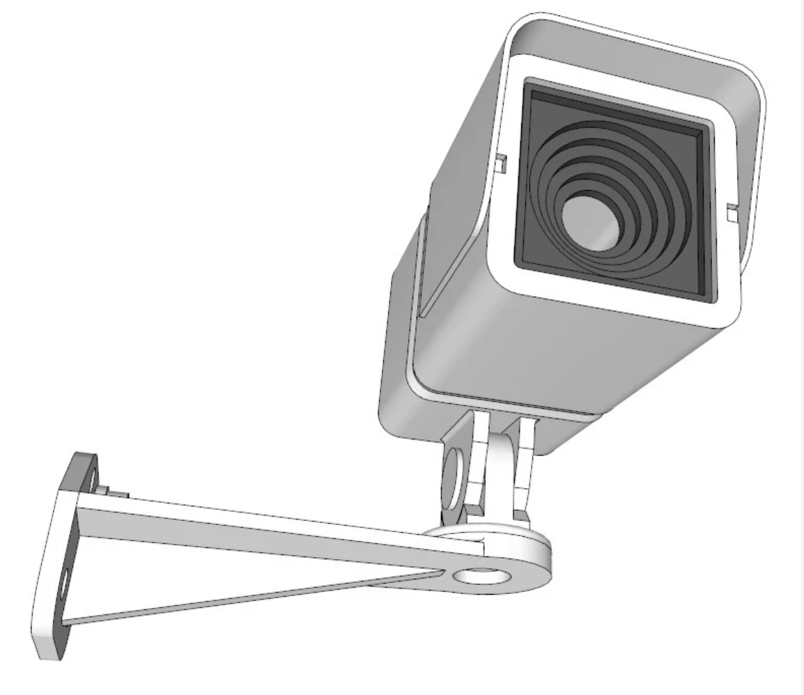
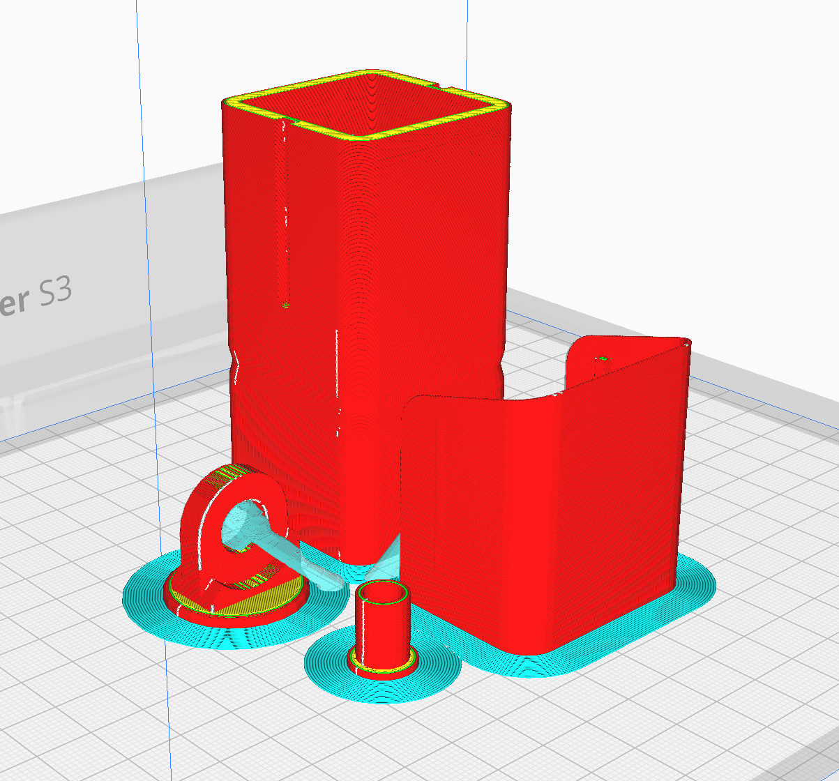
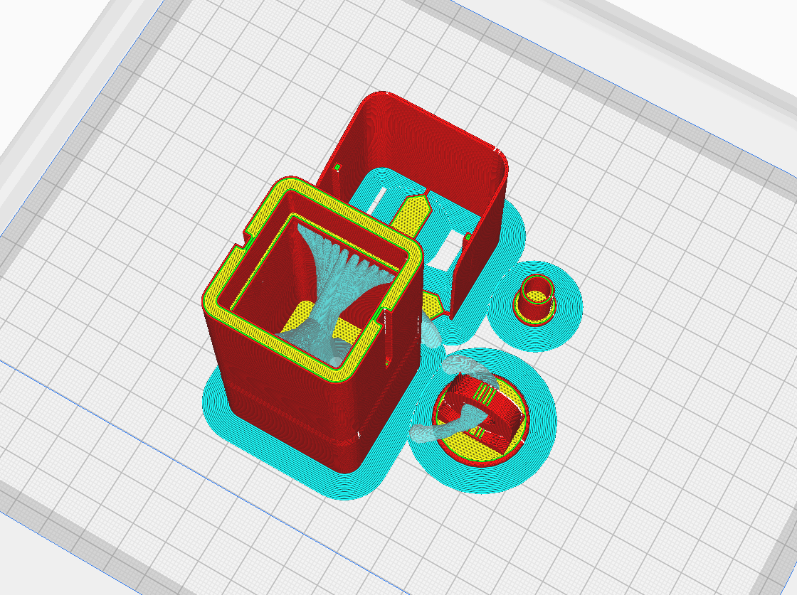
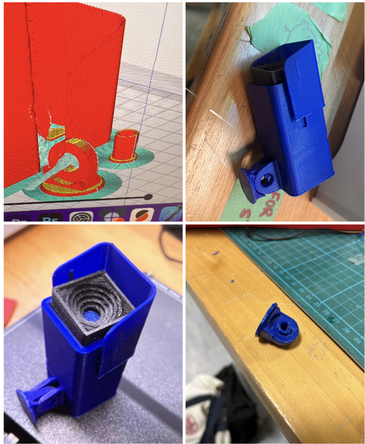
First, with the CCTV camera, I referred to the professor’s slides and came across a website with various 3D models that could be 3D printed. With the professor’s guidance on using the Ultimaker 3, I successfully 3D printed a CCTV camera that was the perfect size for the motor, in my opinion.


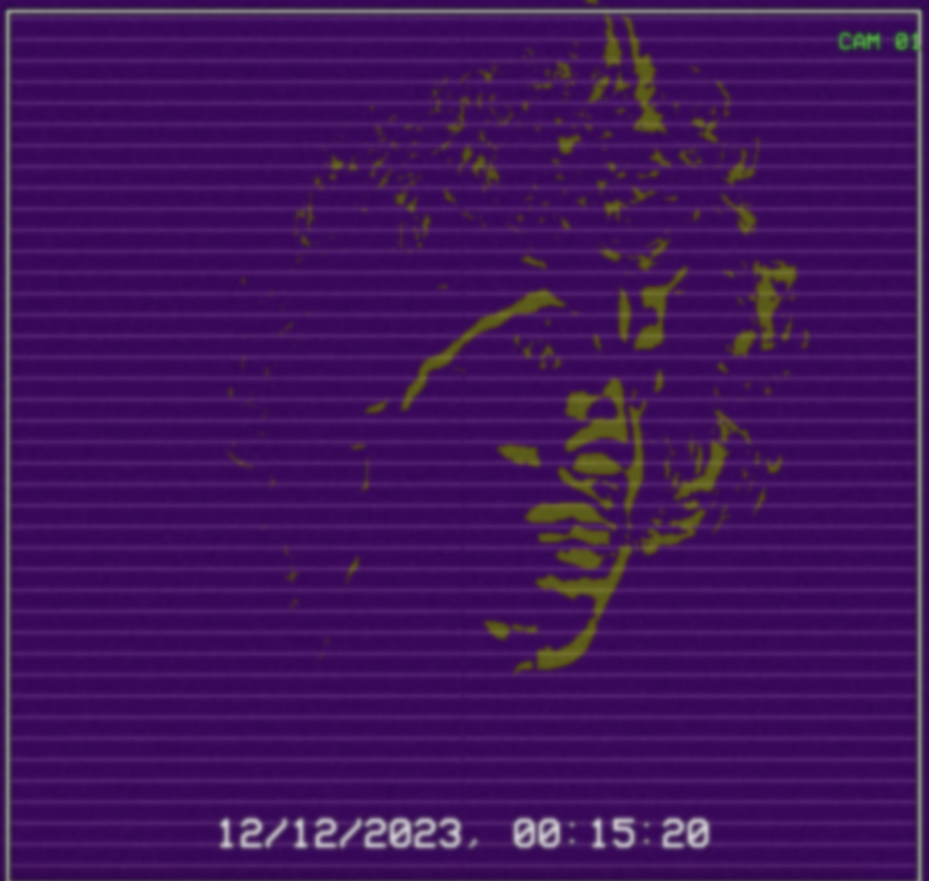
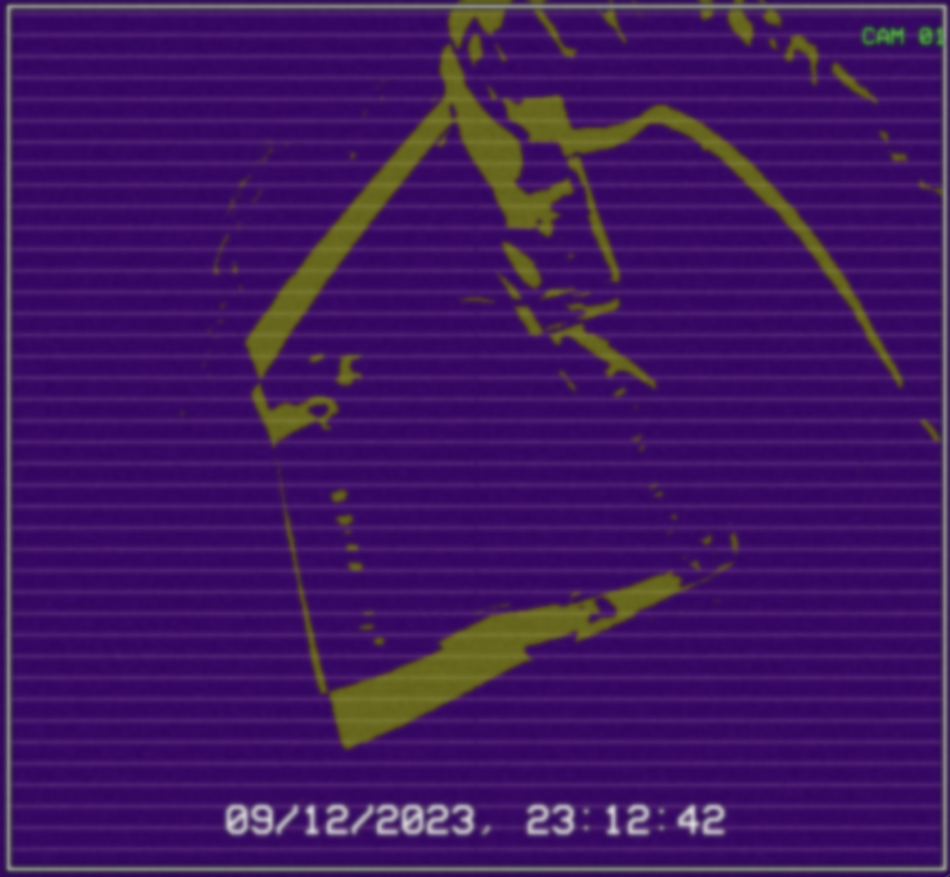
Next, I focused on the p5 interface. As mentioned earlier, I aimed to achieve a motion detection look. By applying multiple layers of effects such as grain, blur, and posterize, I was able to create an old-school CCTV footage vibe while also giving it a unique appearance that doesn’t resemble a typical CCTV camera. I wanted to capture the point of view of a camera trying to detect motion.

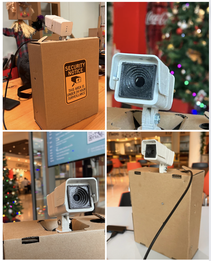
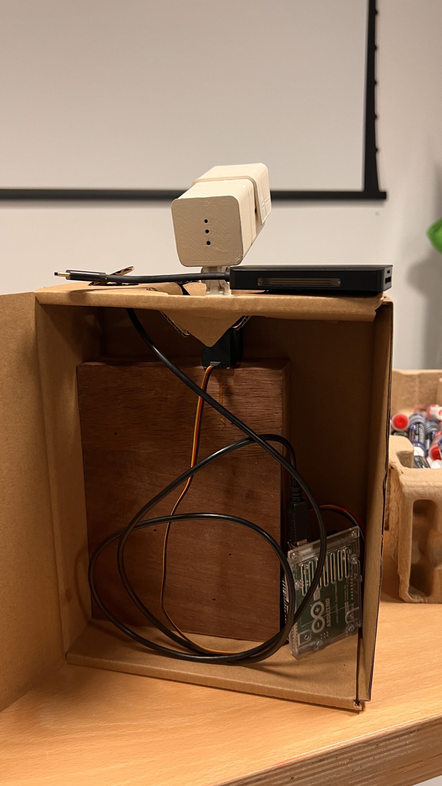
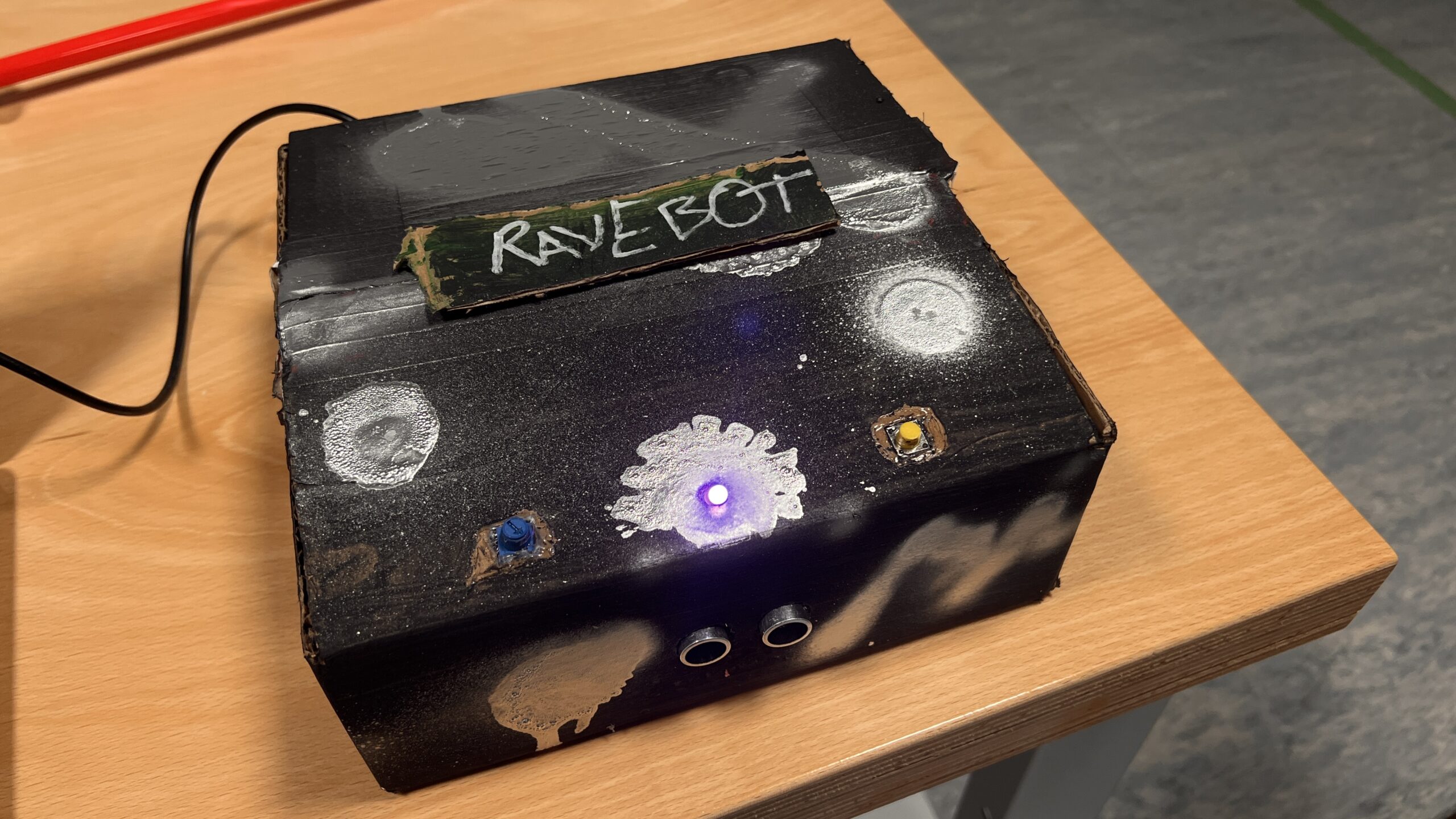
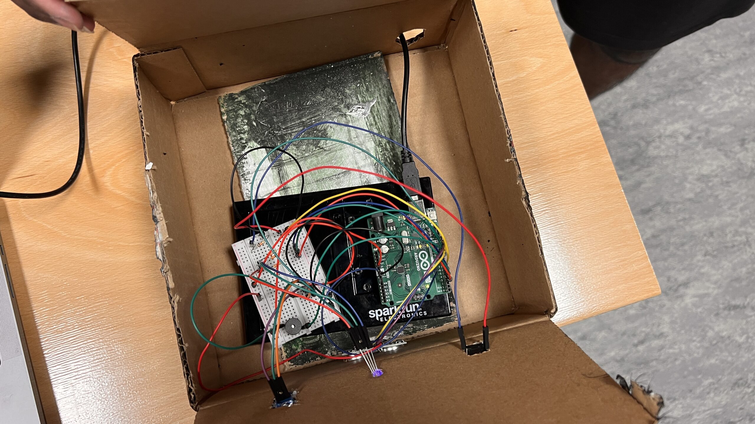
The final step for me was priming and spray painting the CCTV camera white, and finding the right base for it. Since I wanted to position it behind the laptop, I needed a base of suitable height. I found a cardboard box in my room and repurposed it as the shell for the CCTV camera base. I drilled a large piece of wood into it, which serves as a sturdy base for the motor. I then used wood glue to attach the motor to the wood slab, and glued the motor’s base plate to the CCTV camera.

The following is the code for my Arduino and p5 project:

// video, previous frame and threshold for motion detection
let video; 
let prev;
let threshold = 25;

// Variables for motion functions and positions

let mfun = 0;
let motionY = 0;

let lerpX = 0;
let lerpY = 0;

// Font for overlay text and PoseNet related variables

let myFont;
let poseNet;
let pose;
let skeleton;
let loco = 0;

function preload() {
  myFont = loadFont("VCR_OSD_MONO_1.001.ttf");
}

function setup() {
//   low frame rate for a cool choppy motion detection effect
  frameRate(5);

  createCanvas(windowWidth, windowHeight);
  pixelDensity(1);

  video = createCapture(VIDEO);
  video.size(windowWidth, windowHeight);
  video.hide();

    // Create an image to store the previous frame

  prev = createImage(windowWidth, windowHeight);

    // Initialize PoseNet and set up callback for pose detection

  poseNet = ml5.poseNet(video, modelLoaded);
  poseNet.on("pose", gotPoses);
}

// Callback for when poses are detected by PoseNet

function gotPoses(poses) {
  //console.log(poses);
  if (poses.length > 0) {
    pose = poses[0].pose;
    skeleton = poses[0].skeleton;
  }
}

// Callback for when PoseNet model is loaded

function modelLoaded() {
  console.log("poseNet ready");
}

function draw() {
  
//   Check for serial port
  if (!serialActive) {
    text("Press Space Bar to select Serial Port", 20, 30);
  } else {
    text("Connected", 20, 30);
  }
  
//   Check for pose and get nose pose data

  if (pose) {
    fill(255, 0, 0);
    ellipse(pose.nose.x, pose.nose.y, 20);

//     location of pose nose
    loco = int(pose.nose.x);
//     value mapped for servo motor
    val = int(map(loco, 0, windowWidth, 60, 120));

    print(val);
  }
  
  
  background(0);
// load pixels for motion detection
  
  video.loadPixels();
  prev.loadPixels();

  threshold = 40;

  let count = 0;
  let avgX = 0;
  let avgY = 0;

  // Flip the canvas for video display
  push();
  translate(width, 0);
  scale(-1, 1);
  image(video, 0, 0, video.width, video.height);
  pop();

    // Analyzing the pixels for motion detection

  loadPixels();
  for (let x = 0; x < video.width; x++) {
    for (let y = 0; y < video.height; y++) {
            // Current and previous pixel colors

      let loc = (x + y * video.width) * 4;
      let r1 = video.pixels[loc + 0];
      let g1 = video.pixels[loc + 1];
      let b1 = video.pixels[loc + 2];
      let r2 = prev.pixels[loc + 0];
      let g2 = prev.pixels[loc + 1];
      let b2 = prev.pixels[loc + 2];

      // Calculate color distance

      let d = distSq(r1, g1, b1, r2, g2, b2);

      if (d > threshold * threshold) {
        avgX += x;
        avgY += y;
        count++;
        
        // Fliped motion effect pixels
        let flippedLoc = (video.width - x - 1 + y * video.width) * 4;
        pixels[flippedLoc + 0] = 155;
        pixels[flippedLoc + 1] = 155;
        pixels[flippedLoc + 2] = 255;
      } else {
        let flippedLoc = (video.width - x - 1 + y * video.width) * 4;
        pixels[flippedLoc + 0] = 190;
        pixels[flippedLoc + 1] = 255;
        pixels[flippedLoc + 2] = 155;
      }
    }
  }

    // Updating the pixels on the canvas

  updatePixels();

    // Calculate the average motion position if significant motion is detected

  if (count > 200) {
    motionX = avgX / count;
    motionY = avgY / count;
  }

  // Mirror the motion tracking coordinates
  //     let flippedMotionX = width - motionX;

  //     lerpX = lerp(lerpX, flippedMotionX, 0.1);
  //     lerpY = lerp(lerpY, motionY, 0.1);

  //     fill(255, 0, 255);
  //     stroke(0);
  //     strokeWeight(2);
  //     ellipse(lerpX, lerpY, 36, 36);
  
//   MOREE EFFECTZZZZ

  filter(INVERT);
  prev.copy(
    video,
    0,
    0,
    video.width,
    video.height,
    0,
    0,
    prev.width,
    prev.height
  );
  filter(ERODE);
  filter(POSTERIZE, random(10, 20));
  
  drawGrid(); // Draw the grid on top of your content

  drawSurveillanceOverlay(); //surveillance overlay cam
  drawGrain(); // grain effect for old school cctv vibes

  filter(BLUR, 1.5); // blur effect to achieve that vhs quality
}

function distSq(x1, y1, z1, x2, y2, z2) {
  return sq(x2 - x1) + sq(y2 - y1) + sq(z2 - z1);
}

  // toggle full screen

function mousePressed() {
  if (mouseX > 0 && mouseX < width && mouseY > 0 && mouseY < height) {
    let fs = fullscreen();
    fullscreen(!fs);
  }
}


function drawGrain() {
  loadPixels();
  for (let i = 0; i < pixels.length; i += 4) {
    let grainAmount = random(-10, 10);
    pixels[i] += grainAmount; // red
    pixels[i + 1] += grainAmount; // green
    pixels[i + 2] += grainAmount; // blue
    // pixels[i + 3] is the alpha channel
  }
  updatePixels();
}

function drawSurveillanceOverlay() {
  textFont(myFont); // Set the font
  textSize(32); // Set the text size
  
  // Draw border
  noFill();

  strokeWeight(5);

  stroke(0, 0, 0, 255);

  rect(9, 9, width - 16, height - 16);
  stroke(250, 250, 250, 255);
  strokeWeight(2.1);

  rect(9, 9, width - 16, height - 16);

  // Display timestamp
  fill(250, 50, 50);
  fill(250, 250, 250);

  stroke(0, 120);

  textSize(30);
  textAlign(CENTER, TOP);
  text(
    new Date().toLocaleString(),
    windowWidth / 2,
    windowHeight - windowHeight / 11
  );

//  cam 01
  textSize(17);
  fill(50, 250, 55);
  text("CAM 01", width - width / 19, windowHeight / 29);
}

function drawGrid() {
  let gridSize = 15; // Size of each grid cell
  
//   only the horizontal lines

  stroke(205, 3); // Grid line color (white with some transparency)
  strokeWeight(1); // Thickness of grid lines

  for (let x = 0; x <= width; x += gridSize) {
    for (let y = 14; y <= height + 16; y += gridSize) {
      // line(x, 10, x, height);
      line(11, y, width - 10, y);
    }
  }
}

// serial connection
function keyPressed() {
  if (key == " ") {
    // important to have in order to start the serial connection!!
    setUpSerial();
  }
}

function readSerial(data) {
  ////////////////////////////////////
  //READ FROM ARDUINO HERE
  ////////////////////////////////////

  if (data != null) {
    // make sure there is actually a message
    // split the message
    let fromArduino = split(trim(data), ",");
    // if the right length, then proceed
    if (fromArduino.length == 2) {
      // only store values here
      // do everything with those values in the main draw loop
      print("nice");
      // We take the string we get from Arduino and explicitly
      // convert it to a number by using int()
      // e.g. "103" becomes 103
    }

    //////////////////////////////////
    //SEND TO ARDUINO HERE (handshake)
    //////////////////////////////////
    let sendToArduino = val + "\n";
    writeSerial(sendToArduino);
  }
}

p5 👆

#include <Servo.h>

Servo myservo;  // create servo object to control a servo


void setup() {

  Serial.begin(9600);

  myservo.attach(9);

  // start the handshake
  while (Serial.available() <= 0) {
    digitalWrite(LED_BUILTIN, HIGH); // on/blink while waiting for serial data
    Serial.println("0,0"); // send a starting message
    delay(300);            // wait 1/3 second
    digitalWrite(LED_BUILTIN, LOW);
    delay(50);
           myservo.write(0);                  // sets the servo position according to the scaled value

  }
}

void loop() {
  // wait for data from p5 before doing something
  
  while (Serial.available()) {
    Serial.println("0,0");
    digitalWrite(LED_BUILTIN, HIGH); // led on while receiving data
    int value = Serial.parseInt();
    if (Serial.read() == '\n') {
       myservo.write(value);                  // sets the servo position according to the scaled value
    }
  }
}

arduino 👆

Overall, I am happy with how the project was realized. It has been a very educational experience for me, as it has allowed me to learn about posenet, 3D printing, and visual effects. These skills will be valuable for my future capstone project, which will focus on surveillance.


Documentation/User Testing from the IM Showcase:


Final Project Draft

Currently I have figured out the connection between arduino and p5 so that based on poseNet I can move the servo as if it is following me. I have done this on the basis of getting the position of nose pose and sending it to arduino mapped to the servo range. Currently it works as intended however I think it might be a bit off when I am at extreme edges of the canvas video. I am thinking of rectifying by getting a distance variable for my next draft where i will use the distance between eyes to maybe get a more accurate angle.

I will follow a cardboard tutorial to make the CCTV:

let video;
let poseNet;
let pose;
let skeleton;
let loco= 0;

function setup() {
  createCanvas(640, 480);
  video = createCapture(VIDEO);
  video.hide();
  poseNet = ml5.poseNet(video, modelLoaded);
  poseNet.on('pose', gotPoses);
}

function gotPoses(poses) {
  //console.log(poses); 
  if (poses.length > 0) {
    pose = poses[0].pose;
    skeleton = poses[0].skeleton;
  }
}


function modelLoaded() {
  console.log('poseNet ready');
}

function draw() {
  
   if (!serialActive) {
    text("Press Space Bar to select Serial Port", 20, 30);
  } else {
    text("Connected", 20, 30);
  }
  
  image(video, 0, 0);

  if (pose) {
    
    fill(255, 0, 0);
    ellipse(pose.nose.x, pose.nose.y, 20);
   
    loco = int(pose.nose.x);
    val = int(map(loco, 0, 640, 0, 180));

    print(val)
    
  
  }
}

function keyPressed() {
  if (key == " ") {
    // important to have in order to start the serial connection!!
    setUpSerial();
  }
}

function readSerial(data) {
  ////////////////////////////////////
  //READ FROM ARDUINO HERE
  ////////////////////////////////////

  if (data != null) {
    // make sure there is actually a message
    // split the message
    let fromArduino = split(trim(data), ",");
    // if the right length, then proceed
    if (fromArduino.length == 2) {
      // only store values here
      // do everything with those values in the main draw loop
      print("nice");
      // We take the string we get from Arduino and explicitly
      // convert it to a number by using int()
      // e.g. "103" becomes 103
    
    }

    //////////////////////////////////
    //SEND TO ARDUINO HERE (handshake)
    //////////////////////////////////
    let sendToArduino = val + "\n";
    writeSerial(sendToArduino);
    
  }
}

P5 👆

#include <Servo.h>

Servo myservo;  // create servo object to control a servo


void setup() {

  Serial.begin(9600);

  myservo.attach(9);

  // start the handshake
  while (Serial.available() <= 0) {
    digitalWrite(LED_BUILTIN, HIGH); // on/blink while waiting for serial data
    Serial.println("0,0"); // send a starting message
    delay(300);            // wait 1/3 second
    digitalWrite(LED_BUILTIN, LOW);
    delay(50);
           myservo.write(90);                  // sets the servo position according to the scaled value

  }
}

void loop() {
  // wait for data from p5 before doing something
  
  while (Serial.available()) {
    Serial.println("0,0");
    digitalWrite(LED_BUILTIN, HIGH); // led on while receiving data
    int value = Serial.parseInt();
    if (Serial.read() == '\n') {
       myservo.write(value);                  // sets the servo position according to the scaled value
    }
  }
}

arduino 👆

trial video: https://youtube.com/shorts/h1etPCv24vA


Week 11: Reading Reflection

It has been a while since I considered glasses as a medical necessity, I have also thought of it as someone’s style. I remember there being some associations or connotations with wearing glasses in school, but it was never viewed in the same way as something like a hearing aid. I currently have perfect vision (at least for now :p), but I’ve always seen glasses as something that adds character to a person and how they present themselves. In fact, I’ve even wanted to try wearing glasses (not sunglasses) because they just look cool. The John Lennon glasses, in particular, still seem timeless to me.

This made me wonder why the same hasn’t been done for other devices like hearing aids, and even if they have, why they aren’t as popular as eyewear. I remember an aunt back home who sometimes refused to wear her hearing aid because she didn’t want to be seen as using a “medical apparatus.” Reading about the history of how spectacles shifted from being seen as a “medical necessity” to eyewear was truly eye-opening. It really comes down to perception – how these devices are designed, marketed, and sold to the public.

Week 11: Elora and Saiki Assignment

Assignment 1: Move Ball With Potentiometer

I attached a picture of our setup below:

I took the P5JS sketch we used in class and made a few changes, seen here. First, we created the ellipse. When writing the parameters, we made the x value alpha, because the sketch already set alpha as the value that is reading the Arduino board. In order to read Alpha, we had to make sure we mapped the potentiometer range to the range of the P5JS screen. So when you turn the potentiometer, the x value changes, making the ellipse move backwards and forwards. See the important code snippet below:

ellipse(map(alpha, 0, 1023, 0, width),height/2,60);

Assignment 2: Control LED Brightness From P5JS

We took the same P5JS sketch from the slides and altered it, seen here. Here are the changes we made:

let value = map(mouseX,0,width,0,255);
right = int(value);


We created a new variable called value and then mapped the width of the P5JS screen to the LED values, so that as you moved your mouse horizontally across the screen, the LED brightened and dimmed. We used pin 5 because it supports PWM. The LED connected to Pin 5 was the “right” one in the code we used in class, hence why used “right” above to connect the LED and the P5JS bit above. We also had to go into the Arduino code that we had used in class and changed a bit of that as well.

digitalWrite(leftLedPin, left);
analogWrite(rightLedPin,right);
// digitalWrite(rightLedPin, right);


As you can see, we commented out the digitalWrite regarding the right pin and replaced it with analogWrite so that the LED didn’t just turn on or off, but actually got dimmer and brighter on a spectrum.

Assignment 3: Make The LED Turn On When The Ball Bounces

Here is our video. Here is the link to our sketch.

We combined the Gravity Wind example from the slides with the other P5JS sketch from the slides and changed a few things, seen below:

ellipse(position.x,position.y,mass,mass);
if (position.y > height-mass/2) {
velocity.y *= -0.9; // A little dampening when hitting the bottom
position.y = height-mass/2;


right = 1;
}


else {
right = 0;
}


We went to the part of the code where the ball hits the ground, and made it so that the Arduino read the LED as “right,” and the LED turned on (1) and off (0) depending on whether the ball was touching the ground or not.

On a side note, we also made sure that whenever you pressed n, that was how a new circle appeared. Because when we combined the two sketches, it had already been written that pressing the space bar makes the serial bar pop up.

if (key=='n'){
mass=random(70,80);
position.y=-mass;
velocity.mult(0);


Assignment 4: Control Wind With Potentiometer

Last but not least, we made the ball move left and right with the potentiometer by adding this bit of code.

wind.x = map(alpha,0,1023,-1,1);


We mapped the values of the potentiometer onto the wind values already established in the code. So that when we turned the potentiometer right, the ball went right (1) and left (-1) when we turned the potentiometer left.

Neil Leach Talk Reflection

Neil Leach’s talk on AI went pretty much as I expected. After attending another AI talk the day before, it always seems like people, especially during Q&A sessions, are very interested in the ethical implications of AI. And why wouldn’t they be? My capstone project focuses on surveillance systems and facial recognition technologies that are used to target marginalized groups in oppressive contexts. When I see a mid-journey or a DALL E image, I’m not amazed by how advanced our technology has become in generating text to image. Instead, I struggle with the fact that these deep learning models are also used for facial recognition, deepfake technology, and the spread of fake news. They are likely to replace countless blue-collar and white-collar jobs. For me, the negatives far outweigh the positives of using illegal copyrighted datasets to create images. The excuse of the “blackbox” has been used too often to argue against regulating AI, but I believe there needs to be a pause if not regulation. The legal process of regulating AI cannot keep up with the rapid pace at which AI is transforming, and it is a frightening time. I don’t care much about architecture being built through AI when these deep learning models have been repeatedly used in surveillance systems by regimes like Israel in their occupation, leading to the destruction in Gaza, countless lives lost, buildings in rubble. What’s the point of creation when it comes at the cost of life?

Israel/OPT: Israeli authorities are using facial recognition technology to entrench apartheid

Week 10 Reading Reflection

Bret Victor’s rant and point of view is something I hadn’t really considered before. It’s important to keep in mind that the article was written in 2010 when touchscreen technology was still in a rather abysmal state. At that time, the way we interacted with devices was a topic of contention. Today, touchscreen interaction has become the norm and it doesn’t seem likely to change anytime soon. While there may be some introduction of haptic gimmicks, it appears that we are moving away from a touch-centric approach, as we have seen since the transition from keypad phones to touchscreen phones. I still remember when BlackBerry used to be the top phone when I was young. The switch from rotary phones to even keypad phones must have been revolutionary at some point.

What the article made me more aware of is the sense of touch. I hadn’t considered how complex our hands are in terms of the different sensory information they gather, such as weight distribution and temperature. It relates to Bret’s rant about wanting to explore and be in touch with this haptic-centric view. It reminded me that I hadn’t played the guitar in a while, so I picked it up. You know, the first time you play the guitar after a long break, your fingertips kind of hurt, even though they are callused from before. There is a visceral reaction when I played the instrument, unlike when I play the guitar on GarageBand, for example. I feel like I have more control over the sound of the guitar, the pressure I put on the strings, palm muting, and sliding the strings. All of these actions provide such good feedback in my opinion when I’m actually playing the instrument. After reading the article, I became more appreciative of this.

Saiki and Elora Week 10 Assignment: RaveBot


Concept:

Our concept was to create an industrial DJ bot called the Rave Bot. Using an ultrasonic sensor, we aimed to create a metallic, grungy music box with a theremin-like instrument. Given its rave theme, we wanted to incorporate a strobing light effect to enhance the energetic vibe.For the theremin sound, we chose a haunted eerie techno sound, similar to the actual theremin sound.

Prototype and Modelling:

Code:

const int PIN_RED = 3;    //Red LED on pin 9
const int PIN_GREEN = 5;  //Green LED on pin 10
const int PIN_BLUE = 6;   //Blue LED on Pin 11

//variables to hold our color intensities and direction
//and define some initial "random" values to seed it

int red = 254;
int green = 1;
int blue = 127;
int red_direction = -1;
int green_direction = 1;
int blue_direction = -1;
int buttonState = 0;  // variable for reading the pushbutton status


/* This function "Set Color" will set the color of the LED
   rather than doing it over and over in the loop above. */
void setColor(int R, int G, int B) {
  analogWrite(PIN_RED, R);
  analogWrite(PIN_GREEN, G);
  analogWrite(PIN_BLUE, B);
}


#include <Ultrasonic.h>
#include <toneAC.h>

Ultrasonic ultrasonic(12, 13);

#define TONE_VOLUME 5  // 1-20 //output sound pin(positive of speaker)
int distance;

void setup() {
  pinMode(7, INPUT_PULLUP);

  Serial.begin(9600);
  //set all three pins to output mode
  pinMode(PIN_RED, OUTPUT);
  pinMode(PIN_GREEN, OUTPUT);
  pinMode(PIN_BLUE, OUTPUT);
}

void loop() {
  buttonState = digitalRead(7);

  red = red + red_direction;  //changing values of LEDs
  green = green + green_direction;
  blue = blue + blue_direction;
  if (buttonState == LOW) {

    //now change direction for each color if it reaches 255
    if (red >= 255 || red <= 0) {
      red_direction = red_direction * -100;
    }
    if (green >= 255 || green <= 0) {
      green_direction = green_direction * -10;
    }
    if (blue >= 255 || blue <= 0) {
      blue_direction = blue_direction * -150;
    }
    setColor(random(red), random(green), random(blue));

  } else if (buttonState == HIGH) {
    analogWrite(PIN_RED, 10);
    analogWrite(PIN_GREEN, 251);
    analogWrite(PIN_BLUE, 100);
  }

  distance = ultrasonic.read();  //reads the distance from the sensor
  if (distance < 120)            //range is about 120 cm
  {
    int freq = 1500 - distance * 10;  //calculates a corresponding freqeuncy
    toneAC(freq, TONE_VOLUME);        //plays the sound!(output through speaker- pin10)

    Serial.println(distance);  //just for monitoring if required
  } else {
    noToneAC();  //out of range
  }
}


Reflection:

We kept improvising on the theme we wanted to go for, and it turned out great for us. One thing we would have definitely liked is to have a better sounding or louder speaker. Currently, due to the power being split across multiple buttons, LEDs, and the speaker, the full range of volume is lost, especially once we close the box. However, we were really happy with the design of the box. We colored it black and spray painted chrome silver on it to give it an industrial look, which we thought a ravebot deserves. All in all, it was a super fun experience.

Week 9 Reading Reflection

This week’s reading has given me a lot to think about regarding the position of interactive artwork. In a way, I agree with Tigoe that interactive artworks are more like performances. The artist sets up a stage for the interactors, who essentially become the performers in this theater. This reminds me of another class I am taking on installation art, where most successful interactive pieces do not explicitly explain what the piece is about. Instead, they focus on evoking sensory reactions and exploring them in depth, aiming to elicit an emotional response from the performer or “viewers” that prompts further contemplation of the interaction and its significance. Even Andrew Schnieder’s piece, though it may seem like a fixed narrative from a distance, offers different interactions in each group setting, which I find more rewarding than a singular interpretation of paintings in a museum.

The reading on the greatest hits and misses adds another layer to this. Even a seemingly simple and commonly used interaction, such as an LED lighting up when approached, has the potential for further development. It is not an unoriginal idea if the context in which this system is set up provides a feeling that is more contextualized and open to interpretation, which I find appealing. I kinda wanna make a more contextualized theremin now if that’s possible.

Week 9 Assignment : Color Dial

Concept: After seeing what my peers had already done with the assignment guidelines, I wanted to try something different that I hadn’t seen before. Initially, I had the idea of using a color-changing crossroads with an ultrasonic proximity sensor. However, since someone had already done that, I attempted to replicate it using a potentiometer instead. The prototype includes a button that turns on an LED light, and the potentiometer determines the color.

Prototype: During the prototyping phase, I tried to find the most efficient way to minimize the amount of wiring for the three LEDs I wanted. However, I realized that in order to have different LEDs light up for different scenarios, I needed to create separate digital output circuits.

To visualize this, I mapped out the design on TinkerCad, as shown in the following image:

After completing the circuit, I proceeded to the coding part. It took me some trial and error to create a nested loop that worked with the button and potentiometer setup I desired. Since the potentiometer values range from 0 to 1023, I implemented if-else statements for the Red, Yellow, and Green colors based on approximate ranges of 0-300, 300-700, and 700-1000, respectively.

The following is the code:

int buttonState = 0;  // variable for reading the pushbutton status


// the setup routine runs once when you press reset:
void setup() {
  // initialize serial communication at 9600 bits per second:
  Serial.begin(9600);
  pinMode(10, OUTPUT); //Green
  pinMode(11, OUTPUT); //Yellow
  pinMode(12, OUTPUT); //Red
  pinMode(3, INPUT_PULLUP); //Button
}

// the loop routine runs over and over again forever:
void loop() {

  buttonState = digitalRead(3);


  int sensorValue = analogRead(A2);
  Serial.println(sensorValue);

if (buttonState == LOW) {
  if (sensorValue < 300) {
    digitalWrite(12, HIGH);
    digitalWrite(11, LOW);
    digitalWrite(10, LOW);

  } else if (sensorValue < 700) {
    digitalWrite(12, LOW);
    digitalWrite(11, HIGH);
    digitalWrite(10, LOW);

  } else if (sensorValue < 1023){
    digitalWrite(12, LOW);
    digitalWrite(11, LOW);
    digitalWrite(10, HIGH);
  }
} else if (buttonState == HIGH) {
   digitalWrite(12, LOW);
    digitalWrite(11, LOW);
    digitalWrite(10, LOW);
}

  delay(30);  // delay in between reads for stability
}