Final Project [Sizzling Steak]

Concept and the Game Description

Inspired by one of my childhood favorite games, Cooking Mama, I aimed to create a cooking simulation game called Sizzling Steak. Sizzling Steak is an interactive game simulating the experience of the whole steak cooking process from buying the ingredients to putting the sauce on the stake. This game simulates the experience of buying ingredients, cooking a steak on a grill, and putting sauce on the steak through a series of mini-games using various sensors and resistors. 

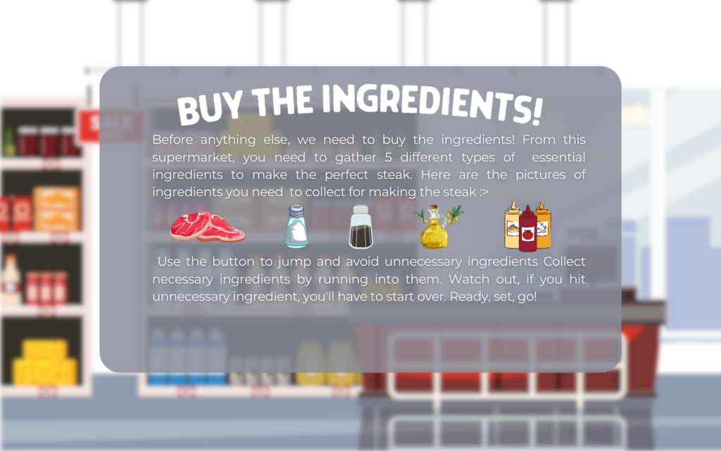
First, the user has to buy ingredients for making the steak. This stage simulates the experience of shopping for ingredients. The player controls the cart using the button switch to avoid obstacles and collect necessary ingredients. 

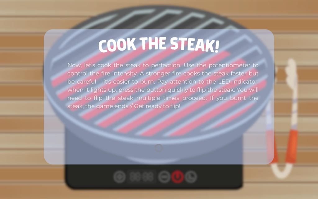
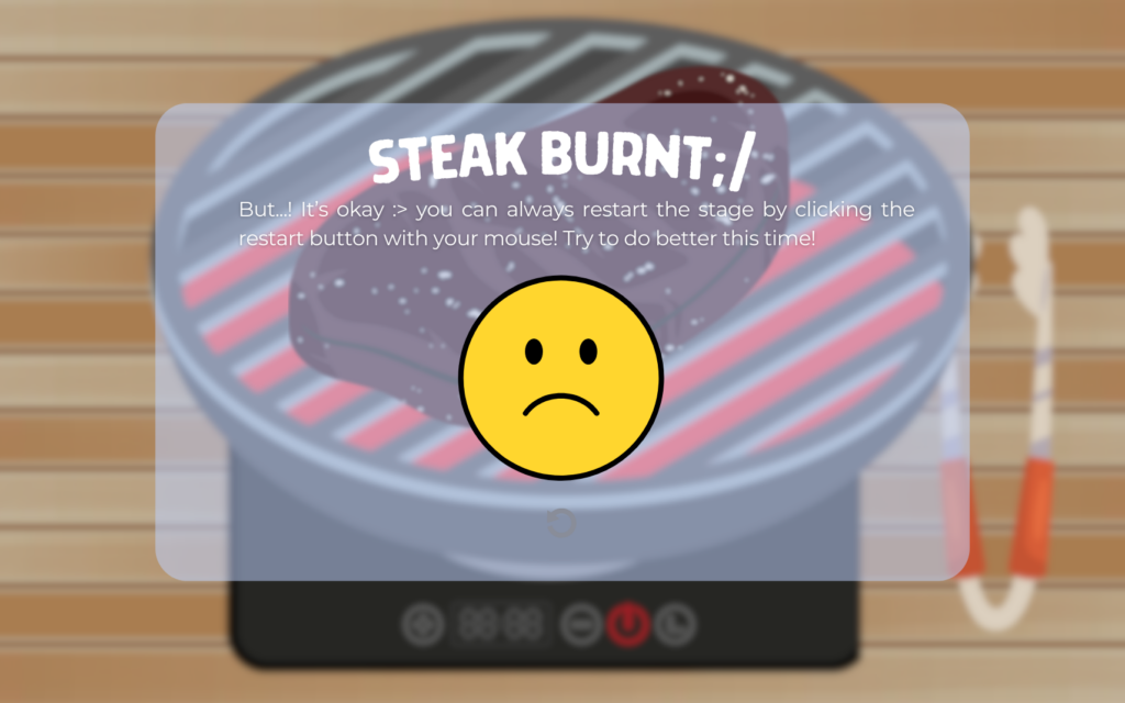
Once the user collects some ingredients, the user proceeds to the cooking the steak stage. In this stage, the player uses a potentiometer to control the fire level on the grill, which is related to the timing of the flipping time. The greater value of the potentiometer indicates a shorter interval of flipping time. When it is time to flip the steak, the LED button lits up, and the player must press the LED button to flip the steak at the right moment. Flipping too late would cause the steak to be burnt.  And the game immediately ends if the steak is burnt. So, the user should flip the steak at the perfect time for a couple of times to succeed in this stage. 

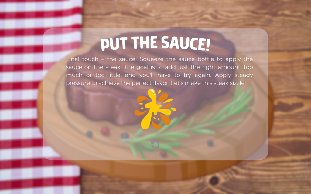
After successfully cooking the steak, the player moves on to putting sauce on it. Here the user should squeeze the sauce bottle with the flex sensor to control the amount of sauce applied. The player must apply the right amount of pressure to achieve the perfect sauce coverage on the steak.

Game pages (without buttons)

Here are some pages and elements I have designed for the interface of this project. I have utilized Canva to design the pages to be utilized in this project:

start page

Stage 1 instructions
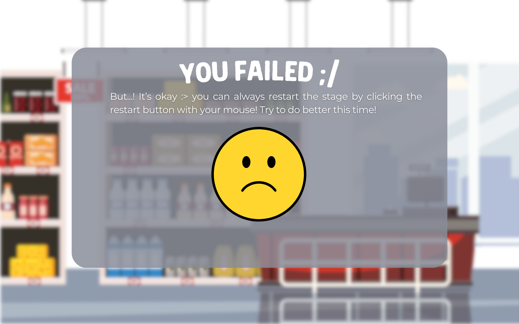
Stage1 lost page 

stage 2 instructions 
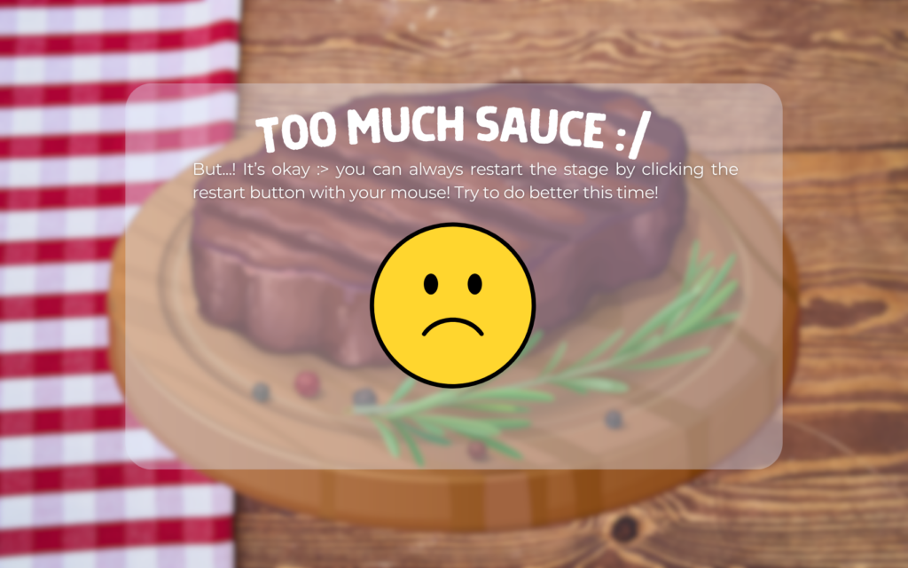
stage 2 lost page

stage3 instructions

stage3 lost page

game ending page

Project Images

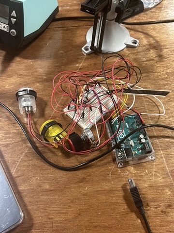
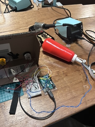
Prototype Development:
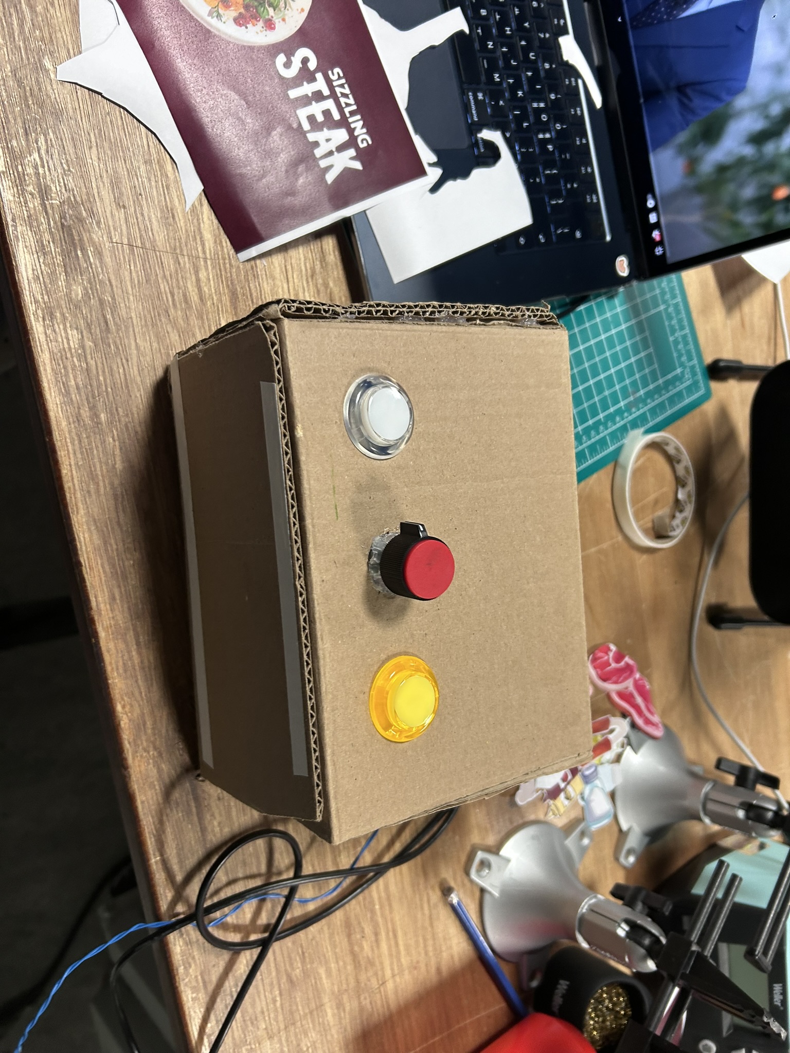
Final Product:

User Testing 


For the user testing, I have let some of my friends play the game  I made without giving them any instructions ( the game’s instruction page was there though) and see how they use it. Thankfully, all of my friends were able to immediately figure out how to play the game. After playing the game, I asked my friends whether there were parts that were confusing and they told me that the game was actually very intuitive. So, there was no particularly confusing part. However, I have discovered that many of them find stage 1 quite difficult to collect 5 ingredients. Hence, as of now, to adjust the level of difficulty, I made the game-winning condition for stage 1 to be collecting 3 ingredients. 

How does the implementation work?

User interaction design

From the brainstorming stage of this project, I wanted to ensure that the player could easily understand and engage with the game mechanics. I attempted to do so by making the instructions for each stage as clear and concise and making the physical component of the project as intuitive as possible. Before the “first” attempt of each stage, there is an instruction to guide the user on how to play the game. I especially have put lots of effort into creating the instructions page for stage 1. While I found the mini-games for stages 2 and 3 to be quite intuitive, I recognized that stage 1, involving collecting ingredients, might be more challenging. To address any confusion that may be caused,  I added images of the ingredients that the player needs to collect to clarify the game mechanics. 

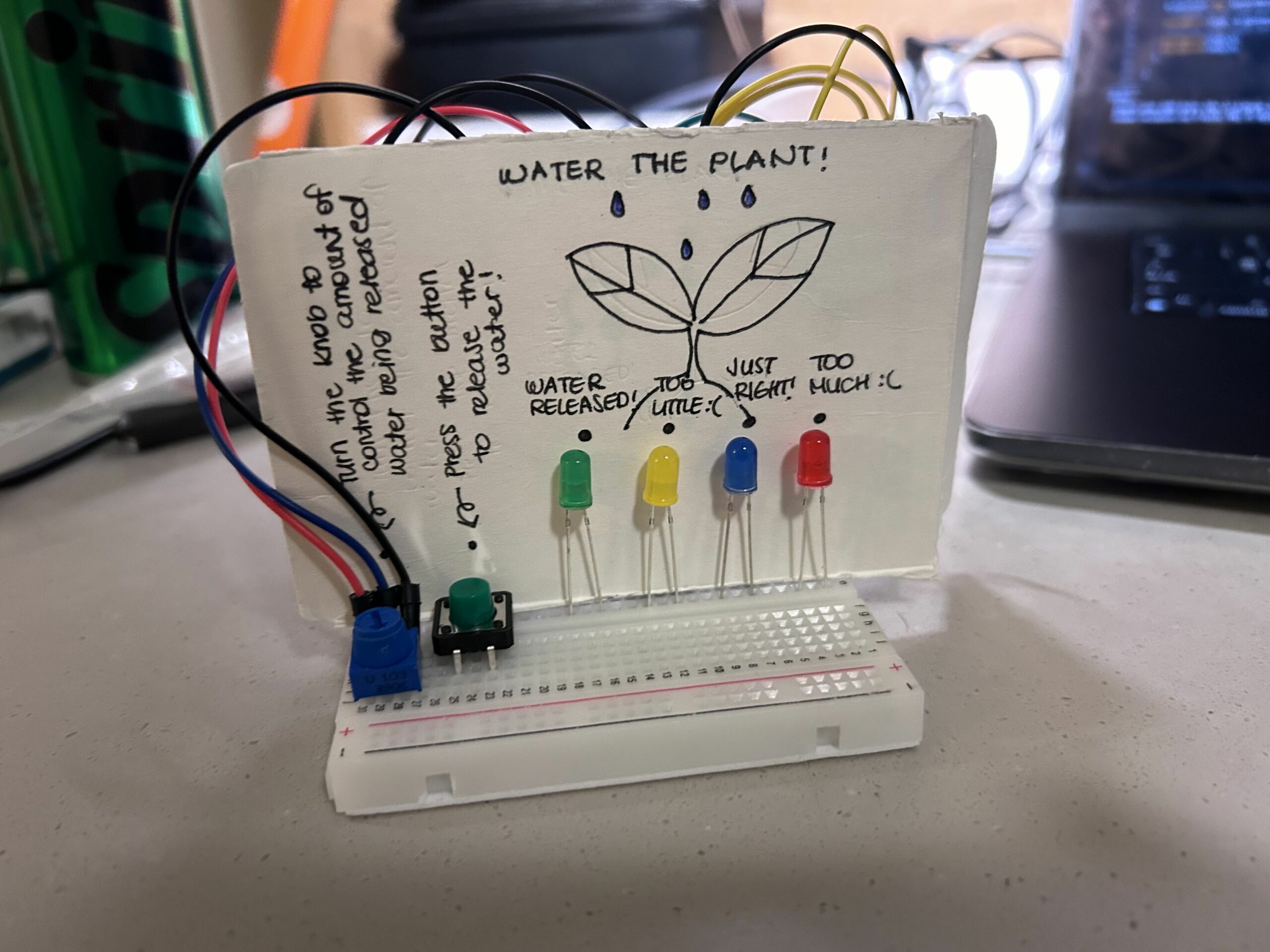
In terms of the physical components of the game, I tried to make it intuitive by utilizing objects similar to those utilized in making the steak. First of all, I have utilized a cute little potentiometer that resembles those attached to the gas stoves to indicate that this is attached to control the “fire intensity”. Then, I inserted the flex sensor into the sauce bottle to signify that the player must “squeeze” the bottle to play the mini-game for stage 3. 

Communication between Arduino and p5.js


In this project, both Arduino and p5.js send data to each other. The Arduino sends the value of different sensors (two buttons, potentiometer, and the flex sensor) to the p5.js while the p5.js sends the “signal” to light up one of the buttons. The Arduino sends a string of the values of the sensors split by commas and the p5.js splits this string to an array of consisting different elements (each element being the sensor value) and utilizes these elements when needed. The p5.js also sends the signal in a string form. In stage 2, when it is not time to light up the button, the p5.js sends “0\n” and sends “1\n” when it is time to light up the button. The Arduino interprets this sent value using the Serial.parseInt(). 

Arduino Code: 

//stage 1 button led;
int led1 = 3;
int button1 = 2;
//stage2 button led;
int led2 = 5;
int button2 = 4;


void setup() {
 Serial.begin(9600);
 pinMode(LED_BUILTIN, OUTPUT);
 pinMode(led1, OUTPUT);
 pinMode(led2, OUTPUT);
  // Initial blink without using delay
 digitalWrite(led1, HIGH);
   while (Serial.available() <= 0) {
   Serial.println("0,0"); // send a starting message
 }


}


void loop() {


 // Handling incoming data
 while (Serial.available()) {
   digitalWrite(LED_BUILTIN, HIGH); // LED on while receiving data
   //interpreting the received data from p5.js
   int lightup = Serial.parseInt();


   //reading the sensors
   int buttonState = digitalRead(button1);
   int sensor1 = analogRead(A5);//potentiometer
   int buttonState2= digitalRead(button2);
   int sensor3= analogRead(A3);//flex sensor


   //sending data to p5.js
   Serial.println(String(buttonState) + "," + String(sensor1) + "," + String(buttonState2)+ "," +String(sensor3));


   //changing the behavior of the led button based on the data sent from p5.js
   digitalWrite(led2,lightup);
   }
}

The Arduino code is quite simple. After starting the handshake with the p5.js, when the serial communication is available, it starts handling the incoming data.  Using Serial.parseInt(), it reads and interprets the data from the p5.js. Then, utilize that data in changing the stage of LED using digitalWrite() later on in the code. As shown in the snippet, the Arduino reads the state and the values of the sensors and buttons using digitalRead() and analogRead(). The buttons’ states are read through digitalRead() and the values of the flex sensor and potentiometer are read through analogRead(). Then, it prints with a new line using Serial.println() to send data to p5.js. 

P5.js Code

Since the p5.js code is very lengthy, here I also attach the link to the entire sketch of the p5.js code (for easier access) 

https://editor.p5js.org/sihyunkim/sketches/ulUBUNDbb

Since my game consists of three mini-games and additional pages, flags were must. The most important flag of my game was gameState. I made gameState as a global variable, and then changed the value of it accordingly to the stage of the game. Here, I will explain the code snippets of different variables of gameState, which are when gameState= “connect port”, “stage1”, “stage2” and “stage3”

The following is how the game worked in each value of gameState: 

  • When gameState= “connect port” 
if (gameState == "connect port") {
  imageMode(CORNER);
  image(page0, 0, 0, windowWidth, windowHeight);
}

if (serialActive && gameState == "connect port") {
  gameState = "start";
}

The game starts with the gameState being “connect port”. Here, if the user connects port using the space bar and makes the serial active, the gameState changes to “start”

  • When gameState= “stage1”
//stage 1
 if (gameState == "stage1") {
   //boost condition 
   if (int(stage1Data) == 1) {
     if (!boostSound.isPlaying()) {
       boostSound.play();
     } else {
       boostSound.stop();
       boostSound.play();
     }
     boost = true; //boost flag to trigger the gamer (cart) to jump
   } else {
     boost = false;
   }

   //background image
   imageMode(CORNER);
   image(stage1bg, 0, 0, windowWidth, windowHeight);

   //calling gamer related functions
   gamer.move();
   gamer.show(cartimg);
   gamer.jump();

   //creating obstacles(unnecessary ingredients) and needed ingredients
   if (millis() - lastObstacleTime > obstacleInterval) {
     //x and y positions of the obstacle
     let obstacleX = windowWidth + 100;
     let obstacleY = windowHeight * 0.75;
     //x and y positions of the ingredient
     let ingredientX = windowWidth + 100;
     let ingredientY = windowHeight * 0.75;
     //initiating the obstacle and ingredient class
     let newIngredient = new Ingredients(ingredientX, ingredientY);
     let newObstacle = new Obstacles(obstacleX, obstacleY);

     //randomly choosing if ingredient or obstacle will be created

     let choice = random(0, 2);

     if (choice >= 1) {
       ingredients.push(newIngredient);
     } else {
       obstacles.push(newObstacle);
     }

     lastObstacleTime = millis();
   }

   for (let i = ingredients.length - 1; i >= 0; i--) {
     ingredients[i].update(-5); //speed of the ingredient coming towards the cart
     ingredients[i].show(ingredientsimg); //depicting the cart
     ingredients[i].checkCollisionGamer(gamer, metIngredientSound); // checking if the ingredient met the gamer

     //removing ingredients if they are off the screen
     if (ingredients[i].position.x + ingredients[i].size / 2 < 0) {
       ingredients.splice(i, 1);
     }
     //letting the ingredients disappear if they meet cart
     else if (metGamer == true) {
       ingredients.splice(i, 1);
       count++;
       metGamer = false;
     }
   }

   for (let i = obstacles.length - 1; i >= 0; i--) {
     obstacles[i].update(-5); //speed of the obstacle coming towards the cart
     obstacles[i].checkCollision(gamer); //checking collision with the cart (gamer)
     obstacles[i].show(obstaclesimg); //depicting the obstacle image

     // removing obstacles if they are off-screen
     if (obstacles[i].position.x + obstacles[i].radius < 0) {
       obstacles.splice(i, 1);
     }
   }
   //if the user collected 3 ingredients it proceeds to the next step.
   if (count == 3) {
     stage1results = "won";
   }
 }

 //results page for stage1
 if (
   gameState == "stage1" &&
   (stage1results == "won" || stage1results == "lost")
 ) {
   metIngredientSound.stop();
   boostSound.stop();
 }

 if (gameState == "stage1" && stage1results == "won") {
   completeSound.play();
   gameState = "stage2instructions";
 } else if (gameState == "stage1" && stage1results == "lost") {
   failSound.play();
   gameState = "stage1lost";
 }

 if (gameState == "stage1lost") {
   imageMode(CORNER);
   image(page3, 0, 0, windowWidth, windowHeight);
   //restart button
   image(
     button3,
     windowWidth / 2 - windowWidth * 0.1,
     windowHeight * 0.75 - windowHeight * 0.05,
     windowWidth * 0.2,
     windowHeight * 0.1
   );
 }

The stage 1 utilizes the same logic as my midterm project for Introduction to Interactive Media. The boost flag is triggered when the received data from the Arduino is 1. When this boost flag is triggered, the cart jumps in the game. Then, using the image() the background image is depicted. The gamer (cart) related functions are called. The game. move() is a function that is responsible for ensuring that the cart always stays inside the canvas and updates the position of the cart with gravity. The gamer.show() is the function responsible for depicting the cart itself and the gamer.jump() is responsible for the “jump” when the boost is triggered.  The if (millis() – lastObstacleTime > obstacleInterval) statement controls the creation of obstacles and ingredients. It checks if enough time has elapsed since the last obstacle/ingredient was created. If so, it generates a new obstacle/ingredient. Then, using random(), we choose if it will be the ingredient or obstacle and we will let it be part of the game. If the choice is greater than or equal to 1, it adds an ingredient to the ingredient list; otherwise, it adds an obstacle to the obstacle list. We go through the list of ingredients and the list of obstacles to depict them, check collision with the gamer, and update them. When the ingredient collides with the gamer (Cart), it adds to the count, but when the obstacle meets the gamer, the stage1results will change to “lost”. When the user collects 3 ingredients, the stage1results becomes “won” which eventually allows the user to proceed to stage 2. 

  • When gameState= “stage2” 
if (gameState == "stage2") {
    fireIntensity = map(int(stage2Data), 0, 1023, 0, 100);
    flipped = int(stage2Data2);
    flipSignal = false;
    imageMode(CORNER);
    image(stage2bg, 0, 0, windowWidth, windowHeight);

    if (!isNaN(fireIntensity)) {
      // flipping the steak
      timeToFlip = map(fireIntensity, 0, 100, 10000, 2000);
      steak.draw(steakimg);
      if (flipped == 1) {
        if (!grillingSound.isPlaying()) {
          grillingSound.play();
        } else {
          grillingSound.stop();
          grillingSound.play();
        }
        steak.flip();
      }
    }
  }
  //stage 2 pages
  if (
    gameState == "stage2" &&
    (stage2results == "won" || stage2results == "lost")
  ) {
    grillingSound.stop();
  }
  if (gameState == "stage2" && stage2results == "won") {
    gameState = "stage3instructions";
    completeSound.play();
  } else if (gameState == "stage2" && stage2results == "lost") {
    gameState = "stage2lost";
    failSound.play();
  }
  if (gameState == "stage2lost") {
    imageMode(CORNER);
    image(page5, 0, 0, windowWidth, windowHeight);
    //restart button
    image(
      button3,
      windowWidth / 2 - windowWidth * 0.1,
      windowHeight * 0.75 - windowHeight * 0.05,
      windowWidth * 0.2,
      windowHeight * 0.1
    );
    steak.reset(); //resetting when the stage2 lost
  }

When the gameState is “stage2”, the fireIntensity is mapped to the potentiometer value from the Arduino and flipped is the value of the button sent from the Arduino. When the fireIntensity is not NaN, i.e., there is a value coming from the Arduino side, timeToFlip is mapped to the fireInensity in the inverse manner, i.e., as the fireIntensity grows larger, timeToFlip becomes smaller. And we depict the image of steak using the steak.draw(). Then, when the flipped==1, i.e., the button is pressed, the steak.flip() . In this steak.flip(), all “flipping related” properties are included. This function is responsible for updating the flipCount, which is counted when the user flipped the steak in perfect timing, and checking whether the steak is “burnt” because the user flipped it too late. When the steak is burnt, the player loses. When the flipCount becomes 6, the stage2results becomes “won” and the player eventually gets a chance to play the third stage

  • When gameState== “stage3”
    if (gameState == "stage3") {
        addPerPress = map(int(stage3Data), 32, 1023, 0, 20);
        if (addPerPress != 0) {
          //playing the sound of the bottle being squeezed
          if (!squishSound.isPlaying()) {
            squishSound.play();
          } else {
            squishSound.stop();
            squishSound.play();
          }
        }
        imageMode(CORNER);
        image(stage3bg, 0, 0, windowWidth, windowHeight);
        sauce.drawSauce(windowWidth / 2, windowHeight * 0.3, 40, 20, sauceimg);
        sauce.drawPercentage(
          windowWidth / 6,
          windowHeight * 0.1,
          windowHeight * 0.1,
          font
        );
    
        let status = sauce.checkSauceLevel();
    
        fill(0);
        textSize(16);
        textAlign(CENTER);
        if (status === "gameWon") {
          stage3results = "won";
        } else if (status === "gameOver") {
          stage3results = "lost";
        }
      }
    
      //results page for stage 3
    
      if (
        gameState == "stage3" &&
        (stage3results == "won" || stage2results == "lost")
      ) {
        squishSound.stop();
      }
    
      if (gameState == "stage3" && stage3results == "won") {
        gameState = "game ended";
        completeSound.play();
      } else if (gameState == "stage3" && stage3results == "lost") {
        gameState = "stage3lost";
        failSound.play();
      }
    
      if (gameState == "stage3lost") {
        sauce.amount = 0;
        imageMode(CORNER);
        image(page7, 0, 0, windowWidth, windowHeight);
        //restart button
        image(
          button3,
          windowWidth / 2 - windowWidth * 0.1,
          windowHeight * 0.75 - windowHeight * 0.05,
          windowWidth * 0.2,
          windowHeight * 0.1
        );
      }
    

    When gameState== “stage3”, addPerPress is mapped to the flex sensor data sent from the Arduino. This addPerPress affects the sauceamount which influences sauce.drawSauce(), a function that depicts the sauce. In sauce.drawSauce(), the addPerPress is continuously being added to the sauceamount. Variables calledsauceWidth and sauceHeight are mapped with the sauceamount. As these variables are utilized in “resizing” the sauce image, as the addPerPress increases, the size of the image increases. The sauce.drawPercentage() depicts the progress of the sauce being released. 100% here indicates that it is in the perfect amount. The color of the text changes based on the percentage range of the sauceamount. 

What are some aspects of the project that you’re particularly proud of?

Honestly, I am so proud of the aesthetics of my project. The starting point of this project was to make “something aesthetically pleasing yet interactive and easy to play with”. So, I have put lots of effort into making the interface of the project cute. Believe or not, but it took me longer to deal with Canva to create the pages and elements used in the project. As much as I’ve put great effort into making the interface, I am very proud of the visual aspects of my project. 


Links to resources used

Challenges faced and how you tried to overcome them

While I did not encounter super “big” challenges working on this project, I have encountered a few minor challenges, which took me quite a long time to figure out. First of all, I have encountered serial communication stopping all of a sudden when the p5.js sketch is ongoing. I was very confused as I thought that I coded everything properly. However, it turned out that I did not initiate the handshake properly between the Arduino and the p5.js. It was just that it worked out of luck. So, following the slides from the class, I rewrote my Arduino code. Another issue I encountered was concern regarding the resizing of elements. While all the elements were resized with the resize of window size, the classes that were initiated inside the setup() were not resized as the setup() is only called once. So, I tried to utilize noLoop(), if-else statements, and other functions, but nothing worked. However, when I ultimately tried to re-initiate the classes that are initialized in the setup() in the windowResized(), it worked. I guess this is because the windowResized() is called only when the window is literally being resized unlike draw() which is continuously being drawn. 

What are some areas for future improvement?

My project could be improved in many ways. One way I could improve my project is to add more stages. For instance, chop some garnishes and cook them as well. Also, I think it would be interesting to make the user select the steak doneness (rare, medium, well done) and adjust the flipping time and flipping count accordingly. Another improvement could be that there will be a judge evaluating the steak that the user cooked. I think these could make my game more interesting and fun.
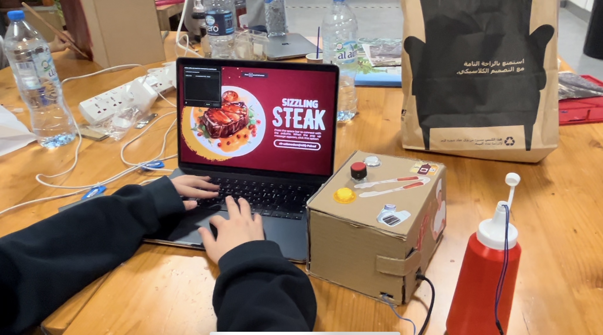
IM SHOWCASE DAY

A video of someone playing my game :

Some pictures from the Showcase: 

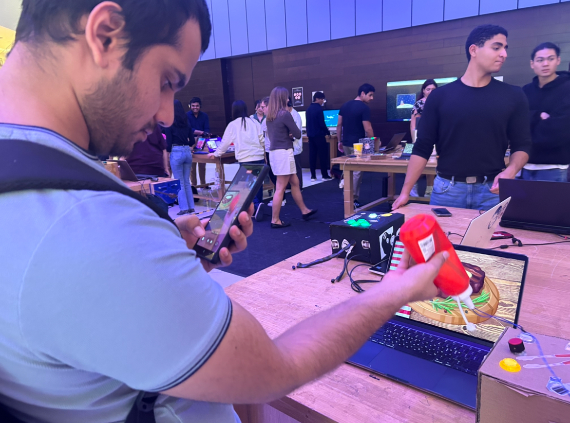
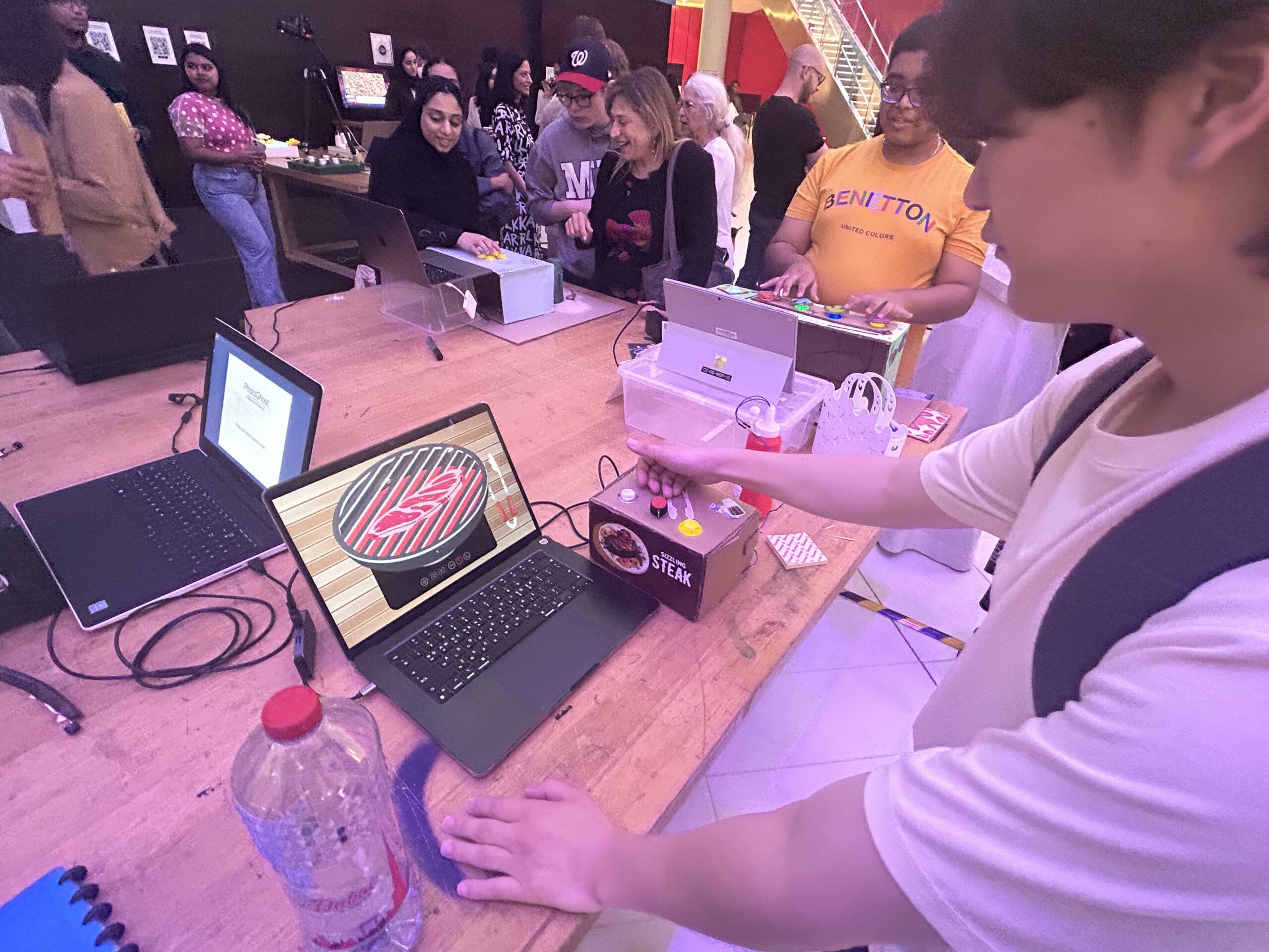
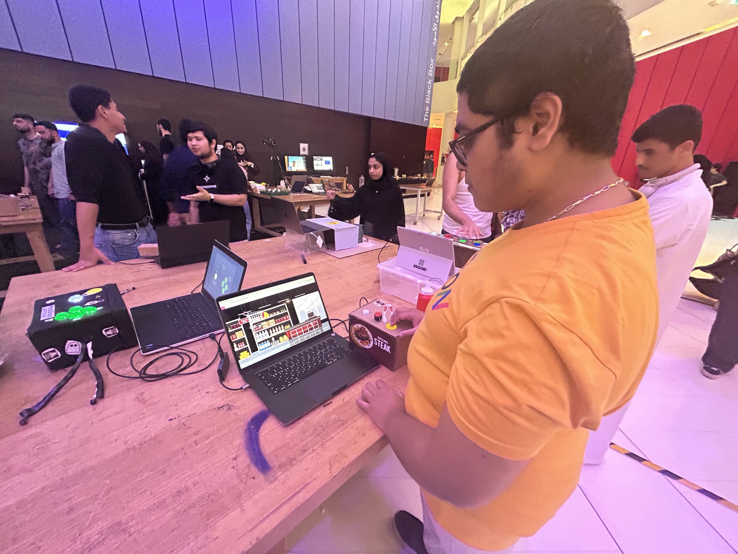
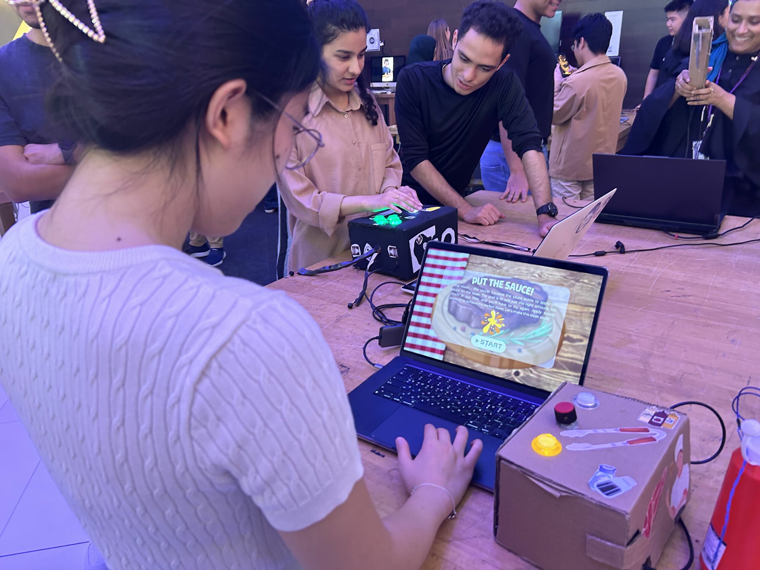
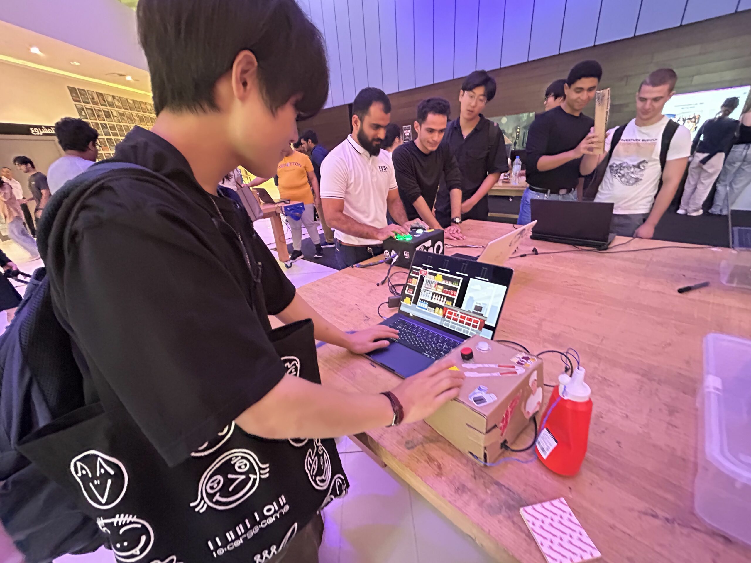
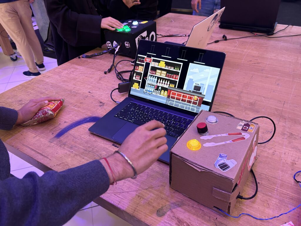
The pictures above are some pictures of people playing my game that I took. My game was way more popular than what I have thought! Many people came to play my game. People especially loved the stage 3 of my game. Lots of people asked me how I made the “squeezing” the sauce physically affect the game itself ((Thanks to the flex sensor!)) From brainstorming to the showcase, this journey of creating the final project was stressful yet very fun.  As always, I have truly enjoyed making the game and working with the Arduino. I cannot believe how the time flies so fast and all IM projects are done. This journey was truly unforgettable and learning experience.
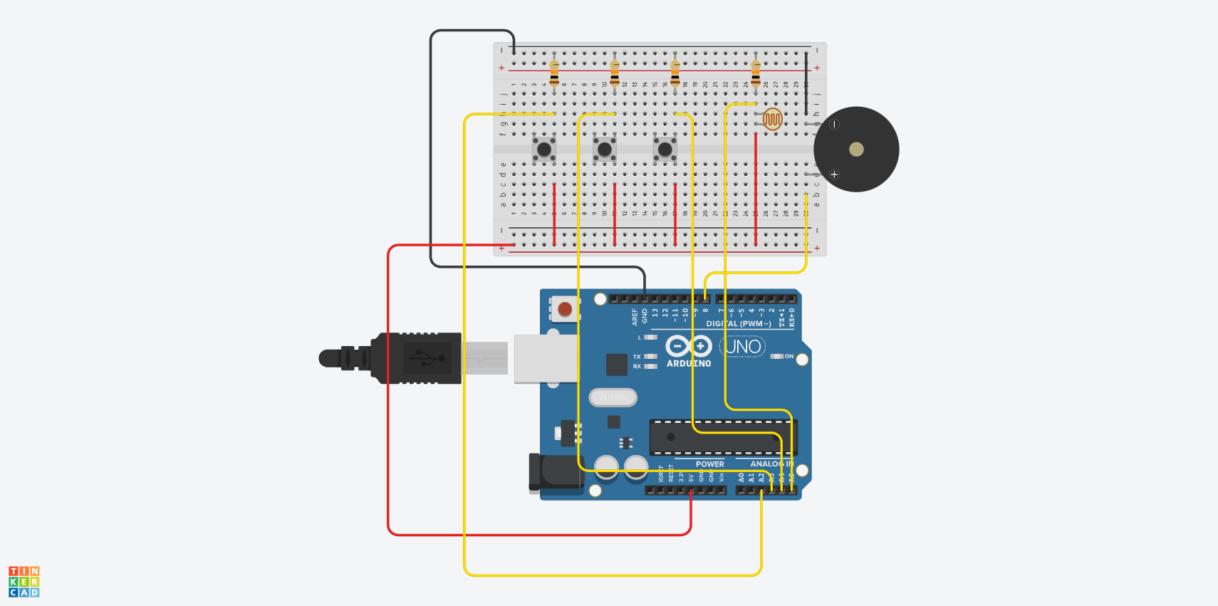
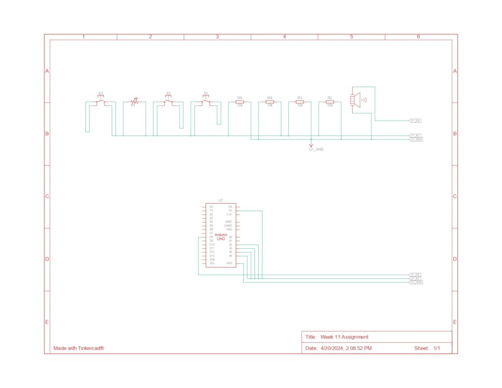
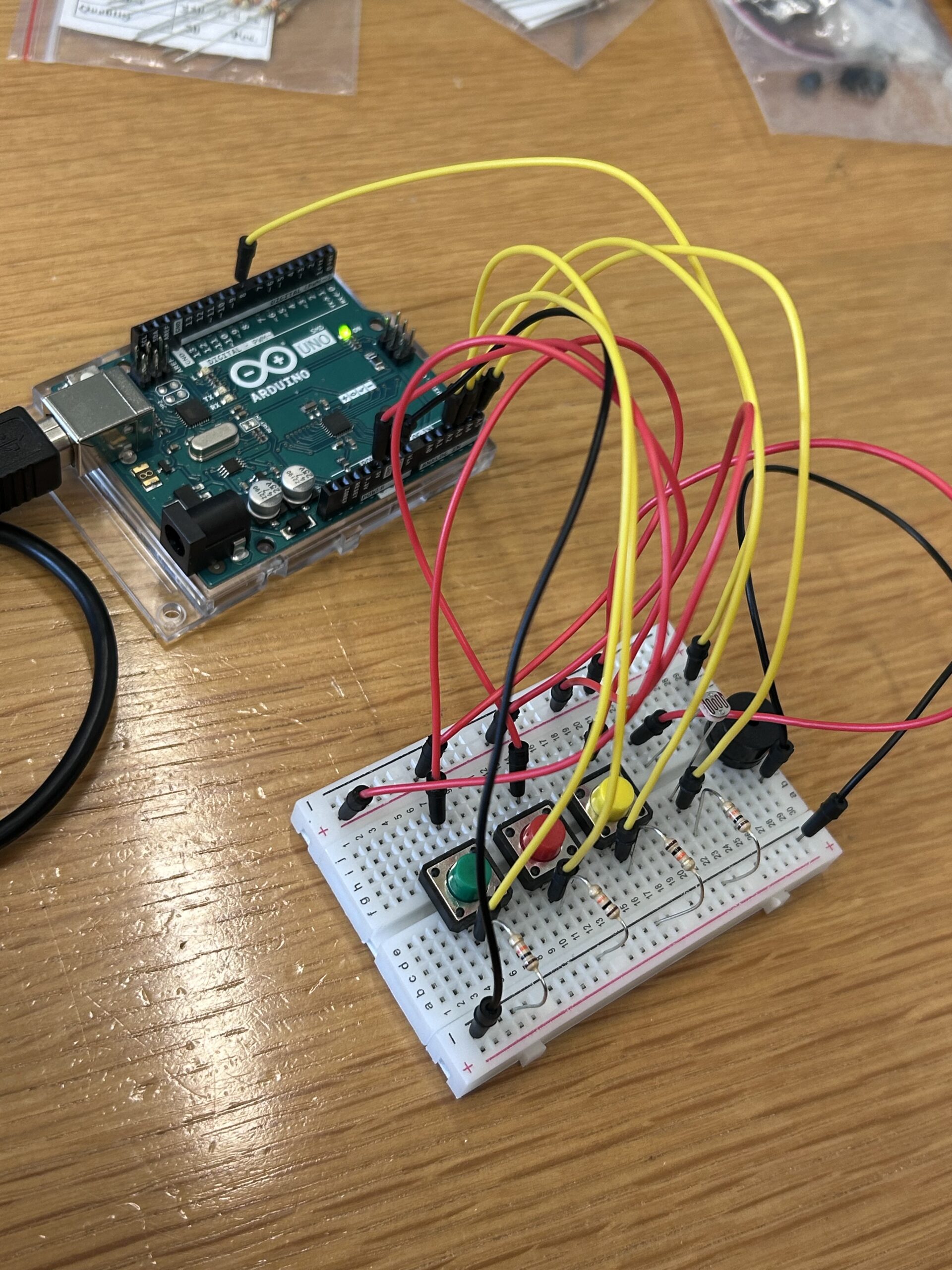
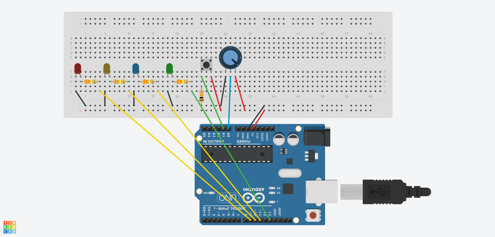
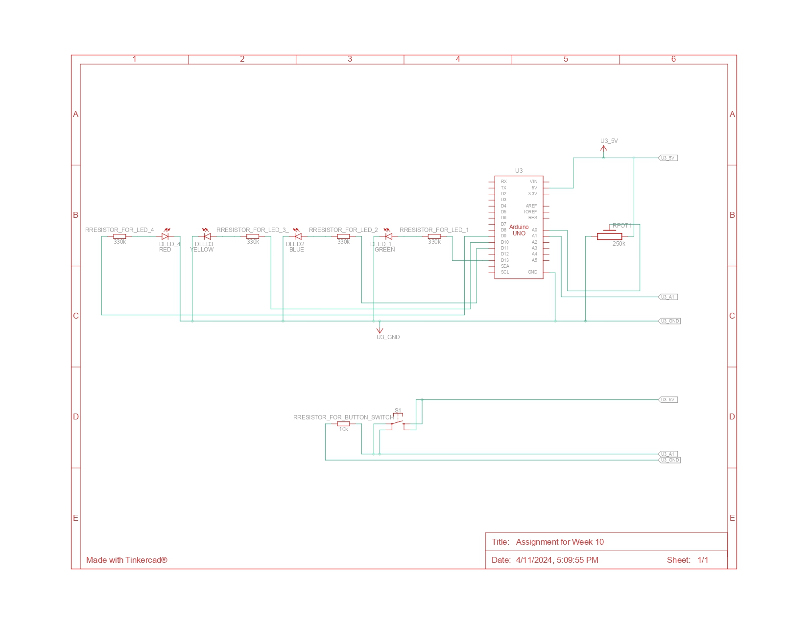
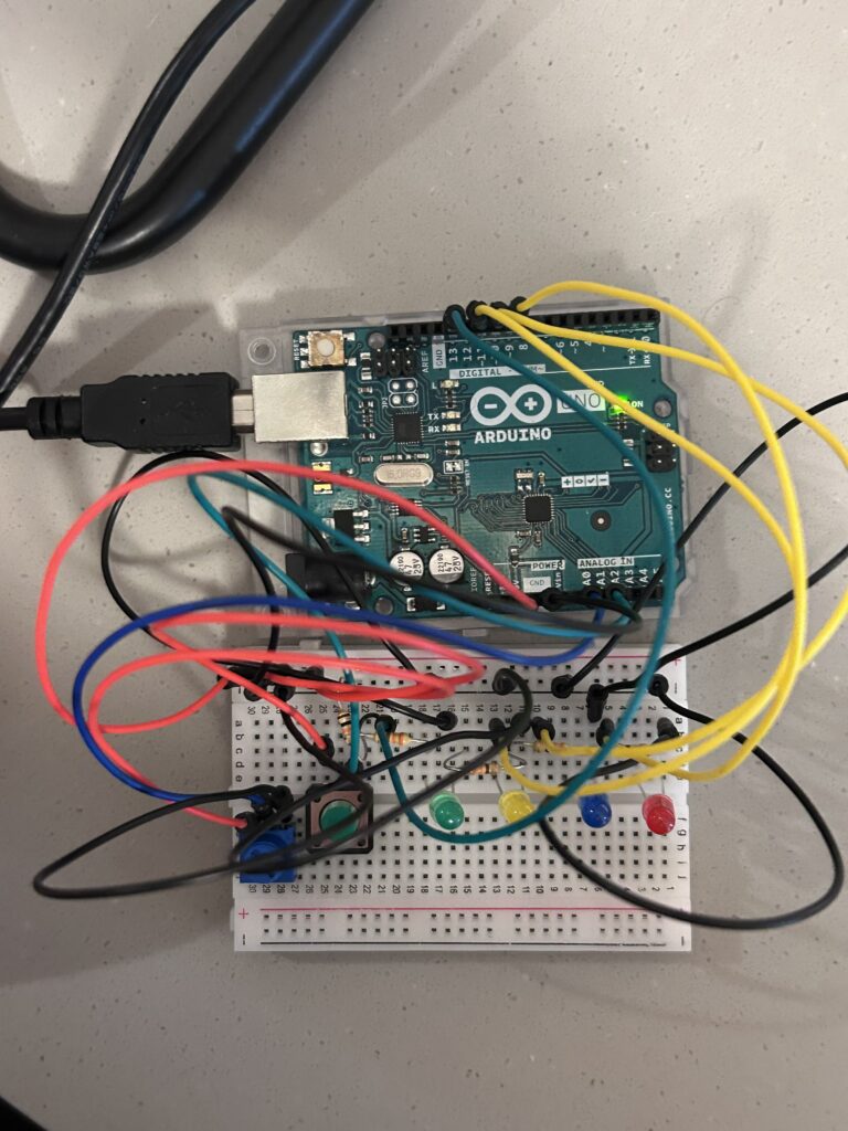
In Class Exercises by Linh and Sihyun

Exercise 1:

Link to the video: https://youtube.com/shorts/4ek33gKQaNY?si=3ArQyArCtsPfHlGx

P5 sketch: 

p5.js Code:

let xposition = 100;
function setup() {
  createCanvas(640, 480);
  textSize(18);
}
function draw() {
  background(0, 255, 0);
  fill(0);
  ellipse(xposition, height / 2, 50, 50);
}

function keyPressed() {
  if (key == " ") {
    // Calls a function to set up the serial connection
    setUpSerial();
  }
}

// Function to read data from the serial port
function readSerial(data) {
  // Check if data received is not null
  if (data != null) {
    // Maps the integer value of data from range 0-1023 to 0-640 and updates xposition
    xposition = map(int(data), 0, 1023, 0, 640);
  }
}

Arduino Code:

void setup() {
  // Start serial communication so we can send data
  // over the USB connection to our p5js sketch
  Serial.begin(9600);
}

void loop() {


      int sensor = analogRead(A0);
      delay(5);
      Serial.println(sensor);
  
}

Circuit: 

For this exercise, we have utilized the potentiometer to change the position of the ellipse in the p5.js sketch. As shown in the code snippet, the ellipse’s x position is mapped to the value of the potentiometer from the Arduino. First of all, by calling the setUpSerial() function when the space bar is pressed, the p5.js sets up the serial connection with the Arduino. Then, using the readSerial(data) the p5.js reads data regarding the potentiometer value from the Arduino. 

For the Arduino, we used Serial. begin(9600) to start the serial communication. Inside the loop function, we have Serial.println(sensor) to send the sensor value to the serial port as a line of text (string), ending in a newline character.

Exercise 2: 

Video:

 P5 sketch: 

P5.js code

In the p5 code, the mouseX is used to control the brightness of the LED light. MouseX is mapped from 0 to width of the canvas to 0 to 255. Utilizing the function readSerial(), we send the value of the mapped mouseX to the Arduino using the below line of codes:

function readSerial(data) {

  if (data != null) {
    //////////////////////////////////
    //SEND TO ARDUINO HERE (handshake)
    //////////////////////////////////
    let sendToArduino = left + "\n";
    writeSerial(sendToArduino);
  }
}

Arduino Code

In the Arduino code, after the initial handshake, the code continuously checks for any data that is sent from the Arduino code. It then parses the sending string and uses that string to control the brightness of the LED using analogWrite. The value has been mapped to the range of 255 so there is no need of mapping again in the Arduino code.

int leftLedPin = 3;


void setup() {
  // Start serial communication so we can send data
  // over the USB connection to our p5js sketch
  Serial.begin(9600);


  // We'll use the builtin LED as a status output.
  // We can't use the serial monitor since the serial connection is
  // used to communicate to p5js and only one application on the computer
  // can use a serial port at once.
  pinMode(LED_BUILTIN, OUTPUT);


  // Outputs on these pins
  pinMode(leftLedPin, OUTPUT);


  // Blink them so we can check the wiring
  digitalWrite(leftLedPin, HIGH);
  delay(200);
  digitalWrite(leftLedPin, LOW);


  // start the handshake
  while (Serial.available() <= 0) {
    digitalWrite(LED_BUILTIN, HIGH); // on/blink while waiting for serial data
    Serial.println("0,0"); // send a starting message
    delay(300);            // wait 1/3 second
    digitalWrite(LED_BUILTIN, LOW);
    delay(50);
  }
}


void loop() {
  // wait for data from p5 before doing something
  while (Serial.available()) {
    digitalWrite(LED_BUILTIN, HIGH); // led on while receiving data


    int left = Serial.parseInt();
    // int right = Serial.parseInt();
    if (Serial.read() == '\n') {
      analogWrite(leftLedPin, left);
      Serial.println();
    }
  }
  digitalWrite(LED_BUILTIN, LOW);
}

Circuit

Exercise 3

Video:

P5.js Sketch

For the LED to light up every bounce, we assigned a flag “ground”. Everytime the ball hits the ground, we set ground = true else it equals to false.

if (position.y > height-mass/2) {
    velocity.y *= -0.9;  // A little dampening when hitting the bottom
    position.y = height-mass/2;
  ground = true;
  }
else{
  ground = false;
}

If ground = true, we will send to arduino the value of 1, else, we will send 0. We did this because we only use digitalWrite in Arduino which only accepts LOW (0) and HIGH (1) as its value.

if (ground) {
     sendToArduino = "1"+"\n";
    }
    else{
       sendToArduino = "0"+"\n";
    }

For the control of the wind, we used the potentiometer to change the value of the wind. Since there is only one data coming from the Arduino, we didn’t use the trim to parse the function. Instead, we directly map the receiving data to the wind value:

wind.x= map(int(data), 0,1023,-1, 1);

Arduino Code: 

int ledPin = 8;


void setup() {
 // Start serial communication so we can send data
 // over the USB connection to our p5js sketch
 Serial.begin(9600);


 // We'll use the builtin LED as a status output.
 // We can't use the serial monitor since the serial connection is
 // used to communicate to p5js and only one application on the computer
 // can use a serial port at once.
 pinMode(LED_BUILTIN, OUTPUT);


 // Outputs on these pins
 pinMode(ledPin, OUTPUT);


 // Blink them so we can check the wiring
 digitalWrite(ledPin, HIGH);
 delay(200);
 digitalWrite(ledPin, LOW);


 // start the handshake
 while (Serial.available() <= 0) {
   digitalWrite(LED_BUILTIN, HIGH); // on/blink while waiting for serial data
   Serial.println("0,0"); // send a starting message
   delay(300);            // wait 1/3 second
   digitalWrite(LED_BUILTIN, LOW);
   delay(50);
 }
}


void loop() {
 // wait for data from p5 before doing something
 while (Serial.available()) {
   digitalWrite(LED_BUILTIN, HIGH); // led on while receiving data


   int led = Serial.parseInt();
   if (Serial.read() == '\n') {
     digitalWrite(ledPin, led);
     int sensor = analogRead(A5);
     Serial.println(sensor);
   }
 }
 digitalWrite(LED_BUILTIN, LOW);
}

In the Arduino sketch, we initiated serial communication with Serial.begin(9600) within the setup() function to set up data transfer at 9600 bits per second. The ledPin variable is set to 8, corresponding to the pin connected to an LED. We use Serial.available() to check for incoming serial data. Initially, the sketch blinks the LED on pin 8 to verify the correct wiring. When it begins receiving data from the serial port, the built-in LED lights up as a signal of data processing. The received data is then used to control the state or brightness of the LED on pin 8. Additionally, the sketch reads the analog value from pin A5 (connected to a potentiometer) and sends this value back to the p5.js, facilitating a continuous, dynamic interaction between the Arduino hardware and the p5.js.

Circuit:

Reflection:

Initially, we had a bit of a problem understanding how the communication between the p5.js and Arduino works. After spending quite a few investigating the sample code, we identified a few of the differences we had in our code and the sample code that caused our code to not work. We also learnt the mapping of values between the p5.js values and the Arduino values (including both variable resistors and analogWrite ranges).

Final Project: Sizzling Steak

Concept

As a child, I played lots of Nintendo games. And one of my favorite games among various Nintendo games was Cooking Mama. Cooking Mama is a game that consists of cookery simulation-styled minigames. By successfully accomplishing each stage of the minigame, the user ends up making a nice-looking cuisine.  Inspired by this game, I would like to create a game called “Sizzling Steak” where the user cooks a steak through three stages. The three stages that consist this game are the following: 

Buying ingredients from the Supermarket: 

In this stage, there would be obstacles and ingredients coming towards the user. By jumping using the button switch, the user should avoid the obstacles and collect the necessary ingredients. Once the user was able to collect 10 necessary ingredients, the stage will successfully end and move to the next stage. However, if the user was not able to successfully avoid the obstacles, the user would have to restart the stage. 

Putting the steak on the grill and cooking it:

In this stage, the user can control the fire intensity using the potentiometer. According to the fire intensity that the user chose, the flip time may be faster or slower. Once it is time to flip, the p5.js will send a signal to the arduino and it will lit up a LED light.  The user would have to flip the steak using the button switch. Here, the user has to flip as fast as she/he can. If the user pressed the button too late, the game would end. The user has to flip around 3-5 times perfectly to successfully end the stage and move to the next stage.

Putting the sauce on the steak: 

In the final stage, the user should squeeze the right amount of sauce on the steak. Here, a flex sensor will be utilized to measure the amount of sauce. The flex sensor will be inserted into a plastic sauce bottle. So, the user will have to squeeze the sauce bottle to play this game. If the user squeezes the bottle too much, there will be too much sauce placed and the user will fail the mission. The goal of this game is to squeeze the bottle with the right pressure and have the right amount of sauce. 

Inspirational images from Cooking Mama: 

Progress so far

So far, I have worked on the game logic of each stage of the game in three separate p5.js sketches. I didn’t put the game-ending conditions yet. 

Here are the links to the sketches: 

Stage 1: https://editor.p5js.org/sihyunkim/sketches/bPDuewgm1

Stage 2: https://editor.p5js.org/sihyunkim/sketches/SPUVViPV3

Stage 3: https://editor.p5js.org/sihyunkim/sketches/wsIpZQBAA


Week 12 Reading Response by Sihyun Kim

Reading the article reminded me of the time when I broke my arm. As a child, I broke my arm after jumping off my cousin’s bed and ended up with a pink cast on my arm. I hated the fact that I had a pink cast because it drew pity from people, which made me uncomfortable. I did my best to hide it by wearing a jacket wherever I went. 

The author of the article points out that ‘the priority for design for disability has traditionally been to enable while attracting as little attention as possible,’ and it was about trying not to project the image of ‘disability’ after all. Interestingly, the article uses eyeglasses as an example of how perceptions can shift. Once a plain and purely functional aid for a disability, eyeglasses have evolved into a fashion statement, celebrated for their aesthetic value and the personal style they add.

According to the article, the eyeglasses were also once functional aid for a disability that tried to “camouflage” the disability by making the eyeglasses “invisible pink plastic glasses”.  Now, we do not think at all that a person has poor eyesight or visional problems just because they wore glasses. This is because eyeglasses also serve as a fashion statement. Reading this article, I realized that “fashion” and “disability” are not two separate concepts that could never be integrated. 

I thought that this shift in how eyeglasses are perceived and other examples in the article showcase the importance of projecting a positive image rather than trying not to project an image at all. And this made me think that this could transform aids from something that people feel they need to hide, as I did with my pink cast, to something they want to showcase.

Reflecting further on this concept, I realized that it is the mindset surrounding disability that often defines it. By adopting an approach that values visibility and style, I believe that we can challenge and change the stigmatizing attitudes that suggest disabilities should be concealed. We can shift from a mindset that views disabilities as deficits to one that recognizes them as a part of human diversity to be accepted and embraced.


Final Project Ideas

Preliminary Project Ideas:

Match the Color! 

I would like to create a game inspired by popular TikTok challenges where users try to replicate the color of various objects by blending multiple colors. In this game, players will attempt to guess the RGB (Red, Green, Blue) values of a color displayed on their monitor. The interface will include three potentiometers, each dedicated to adjusting one of the RGB components. The goal is for players to match their potentiometer settings to the actual RGB values of the displayed color as closely as possible. Success in achieving a close match will result in a win.

Save the Cat

Inspired by Pou, a game I often played as a child, I would like to create a game where the user rescues an abandoned kitten from the street and helps it find a loving family. This game would consist of three stages:

Picture of Pou 

  • Washing the Kitten: Using a potentiometer, the user must control the water temperature to find the perfect warmth for washing the kitten.
  • Medical Treatment for the Kitten: The user will be presented with several choices (e.g., bandages, pills, and ice packs). Based on the kitten’s condition, the user must make appropriate decisions about which items to use, facilitated by button switches.
  • Finding a New Family for the Kitten: The goal is to find a kind-hearted family with positive characteristics. This stage involves a game where the user uses a joystick to avoid bad qualities and collect good ones.

Steak Cooking Game

Inspired by Cooking Mama, one of my favorite games from my childhood, I aim to create a steak cooking game. This game would consist of three stages:

  • Buying Ingredients: This stage is similar to the dinosaur game that appears when there is no internet. Obstacles and ingredients move towards the user, who must use a button switch to dodge the obstacles and collect the necessary ingredients.
  • Cooking the Steak: Initially, the user must start a fire using a potentiometer, adjusting it to find the ideal heat level for the steak. The user must then cook the steak on the grill using button switch,  being cautious not to burn or undercook it.
  • Applying Sauce to the Steak: In this final stage, the user uses a pressure sensor to apply the right amount of sauce to the steak.

Heartbeat-Based Music Player

In this project, I will use a pulse sensor to obtain the user’s heartbeat data. The system will then ask the user to select their mood from four options: happy, sad, angry, or calm. Based on these inputs, the system will recommend music to the user.


Week 11: Reading Response by Sihyun Kim

First of all, I found it very interesting that ‘A Brief Rant on the Future of Interaction Design’ and its follow-up article were written in 2011. In these readings, the author ‘rants’ about a ‘handheld device’ that ignores our hands, advocating instead for a dynamic medium that we can see, feel, and manipulate. It was intriguing how the author ranted about things that have now become a reality. When I first saw the article, I was surprised at how much the video entitled ‘Microsoft- Productivity Future Vision,’ which the author was quite skeptical about, resembles our present.

Both readings made me reflect on all my interactions with the ‘picture under the glasses.’ At the start of the article, I found myself disagreeing with the author’s argument, as I thought that all those simple interactions that the picture under the glasses offers are the ultimate form of interaction. As the author states, interactions with these devices do numb my fingers. However, I had never considered them numbing my tactile sense before reading this article.

Then, the sentence stating ‘My child can’t tie his shoelaces, but can use the iPad’ struck me. I perceived this sentence as a clear illustration of the consequences of tactile numbing while utilizing those ‘pictures under the glasses.’ While tying shoelaces isn’t a hard task, it does require tactile sensation. To young children, who are accustomed to iPads, they might not develop the tactile richness they should have. This could mean that these ‘pictures under the glasses’ might hinder people from developing the capabilities they ought to have.

As stated in one of the readings, I believe that a good tool should address human needs by amplifying human capabilities. However, in the case of those ‘pictures under the glasses,’ can we say that these are good tools in terms of interaction if they hinder us from realizing our full capabilities? Can they even be considered human-centric if they neglect the need for our hands to feel things?

These questions arose for me. Then, I came to realize that we tend to overlook the importance of considering holistic sensory engagement because of our pursuit of technological advancement and convenience. All those ‘pictures under the glasses’ technologies are indeed good tools in terms of their functionalities. They simplify and ease our lives and do amplify human capabilities. However, we have to sacrifice all the tactile richness of working with our hands, as the author said. Overall, reading this article made me realize that it is nearly impossible to have an ultimate tool which can be considered a ‘good’ tool in all aspects as there is always a drawback.


Week 11: Lullaby Box by Sihyun and Linh

Concept

While brainstorming for this assignment, we decided that we would like to make a project that utilizes the photocell and the buttons. The photocell changes its resistance value depending on the light intensity. And this inspired us to explore interactions between light presence and absence. We came up with a cute project called the “Lullaby Box”, which plays nursery rhymes when the photocell is covered and a button is pressed. This project features yellow, red, and green buttons, each corresponding to different songs: ‘Mary Had a Little Lamb,’ ‘Twinkle Twinkle Little Star,’ and ‘Happy Birthday Song,’ respectively. The rationale for the songs playing only when the photocell is covered is tied to the project’s purpose: to soothe children to sleep in the dark.

Schematics and Diagram

The circuit consists of three main parts: the light sensor, the Piezo Speaker, and the buttons. The light sensor is connected to port A5 for analog reading. It acts as a button in the circuit, allowing the song to play when the photocell is covered. The buttons are the main controller of this assignment. They are connected to ports A2, A3, and A4 for digital reading. The song will only play when the photocell is covered (its value is low) and the button is pressed. Each button is responsible for a different song that will be played by the Piezo Speaker (connected to port 8 for digital output).

Arduino Code

#include "pitches.h"
//mary had a little lamb
int melody1[] = {
  NOTE_E4, NOTE_D4, NOTE_C4, NOTE_D4, NOTE_E4, NOTE_E4, NOTE_E4, NOTE_D4, NOTE_D4, NOTE_D4,
  NOTE_E4, NOTE_G4, NOTE_G4, NOTE_E4, NOTE_D4, NOTE_C4, NOTE_D4, NOTE_E4, NOTE_E4, NOTE_E4,
  NOTE_E4, NOTE_D4, NOTE_D4, NOTE_E4, NOTE_D4, NOTE_C4
};
// twinkle twinkle little star 
int melody2[]={
  NOTE_C4, NOTE_C4, NOTE_G4, NOTE_G4, NOTE_A4, NOTE_A4, NOTE_G4, NOTE_F4, NOTE_F4, NOTE_E4,
  NOTE_E4, NOTE_D4, NOTE_D4, NOTE_C4, NOTE_G4, NOTE_G4, NOTE_F4, NOTE_F4, NOTE_E4, NOTE_E4,
  NOTE_D4, NOTE_G4, NOTE_G4, NOTE_F4, NOTE_F4, NOTE_E4, NOTE_E4, NOTE_D4, NOTE_C4, NOTE_C4,
  NOTE_G4, NOTE_G4, NOTE_A4, NOTE_A4, NOTE_G4, NOTE_F4, NOTE_F4, NOTE_E4, NOTE_E4, NOTE_D4,
  NOTE_D4, NOTE_C4
};
// happy birthday 
int melody3[] = {
  NOTE_G4, NOTE_G4, NOTE_A4, NOTE_G4, NOTE_C5, NOTE_B4,
  NOTE_G4, NOTE_G4, NOTE_A4, NOTE_G4, NOTE_D5, NOTE_C5,
  NOTE_G4, NOTE_G4, NOTE_G5, NOTE_E5, NOTE_C5, NOTE_B4, NOTE_A4,
  NOTE_F5, NOTE_F5, NOTE_E5, NOTE_C5, NOTE_D5, NOTE_C5
};


int noteDurations[] = {
  4, 4, 4, 4, 4, 4, 2, 4, 4, 2, 4, 4, 2, 4, 4, 4, 4, 4, 4, 4, 4, 4, 4, 4, 4, 1
};
int noteDurations2[] = {
  4,4,4,4,4,4,2,4,4,4,4,4,4,2,4,4,4,4,4,4,2,4,4,4,4,4,4,2,4,4,4,4,4,4,2,4,4,4,4,4,4,2
};

int noteDurations3[] = {
  8, 8, 4, 4, 4, 2,
  8, 8, 4, 4, 4, 2,
  8, 8, 4, 4, 4, 4, 4,
  8, 8, 4, 4, 4, 2
};


void setup() {
  Serial.begin(9600);
  pinMode(A4, INPUT); // yellow switch

}

void loop() {
  int sensorValue= analogRead(A5);
  int yellowButtonState = digitalRead(A4);
  int redButtonState = digitalRead(A3);
  int greenButtonState= digitalRead(A2);
  // Serial.println(sensorValue);
  if (sensorValue<=800){
  if (yellowButtonState == HIGH) {
    // Play the melody only if the button is pressed
    for (int thisNote = 0; thisNote < 26; thisNote++) {
      // Check the button state inside the loop
      yellowButtonState = digitalRead(A4);
      if (yellowButtonState == LOW) {
        noTone(8);
        break; // Exit the loop if the button is released
      }

      int noteDuration = 1000 / noteDurations[thisNote];
      tone(8, melody1[thisNote], noteDuration);
      int pauseBetweenNotes = noteDuration * 1.30;

      // Use non-blocking delay
      int startTime = millis();
      while (millis() - startTime < pauseBetweenNotes) {
        // Update the button state
        yellowButtonState = digitalRead(A4);
        if (yellowButtonState == LOW) {
          noTone(8);
          break; // Stop the tone if the button is released
        }
      }
      noTone(8); // Ensure the tone is stopped after the loop
    }
  }
  else if (redButtonState == HIGH) {
    // Play the melody only if the button is pressed
    for (int thisNote = 0; thisNote < 42; thisNote++) {
      // Check the button state inside the loop
      redButtonState = digitalRead(A3);
      if (redButtonState == LOW) {
        noTone(8);
        break; // Exit the loop if the button is released
      }

      int noteDuration = 1000 / noteDurations2[thisNote];
      tone(8, melody2[thisNote], noteDuration);
      int pauseBetweenNotes = noteDuration * 1.30;

      // Use non-blocking delay
      int startTime = millis();
      while (millis() - startTime < pauseBetweenNotes) {
        // Update the button state
        redButtonState = digitalRead(A3);
        if (redButtonState == LOW) {
          noTone(8);
          break; // Stop the tone if the button is released
        }
      }
      noTone(8); // Ensure the tone is stopped after the loop
    }
  }
    else if (greenButtonState == HIGH) {
    // Play the melody only if the button is pressed
    for (int thisNote = 0; thisNote < 25; thisNote++) {
      // Check the button state inside the loop
      greenButtonState = digitalRead(A2);
      if (greenButtonState == LOW) {
        noTone(8);
        break; // Exit the loop if the button is released
      }

      int noteDuration = 1000 / noteDurations3[thisNote];
      tone(8, melody3[thisNote], noteDuration);
      int pauseBetweenNotes = noteDuration * 1.30;

      int startTime = millis();
      while (millis() - startTime < pauseBetweenNotes) {
        // Update the button state
        greenButtonState = digitalRead(A2);
        if (greenButtonState == LOW) {
          noTone(8);
          break; // Stop the tone if the button is released
        }
      }
      noTone(8); // Ensure the tone is stopped after the loop
    }
  }
   else {
    noTone(8); // Ensure the tone is stopped if not in the loop
  }
}}

Firstly, we initialize the code with arrays of the melody we will play. There are 3 different songs: ‘Mary Had a Little Lamb,’ ‘Twinkle Twinkle Little Star,’ and ‘Happy Birthday Song’. Each song will have one array for the notes and another array for the note durations.

Next, we initialized all the input readings at A2, A3, A4, and A5 for the buttons and the photocell. To run the songs, we continuously check for the value of the photocell to allow the buttons to turn on the songs. If the photocell is covered (the value is low), the song will play according to the buttons. For each note that is about to play, the code will check for the state of the button whether it is pressed or not. If the button is not pressed, the song will stop playing immediately.

Built Circuit Based on the Diagram

Demonstration of the Final Outcome

Challenges and Reflection 

 We genuinely enjoyed tackling this assignment, despite its initial challenges. Creating the melodies was particularly tricky since neither of us is knowledgeable about musical composition and notes. Eventually, we grasped what was required and made progress.

A weird issue arose while we were constructing the circuits for this project. To determine the resistance value of the photocell, we attempted to use code and the serial monitor. However, we discovered that the photocell was malfunctioning. Initially, we suspected errors in our coding or circuit assembly. Despite repeatedly consulting past lecture slides, re-uploading the code, and rebuilding the circuit, we couldn’t pinpoint any mistakes. Then, quite mysteriously, the photocell began functioning correctly after another code upload. We still don’t understand the cause of this issue. Aside from this strange incident, we encountered no significant problems throughout the project

For improvement, we would like to add more button switches and songs for the variety of choices.  In this way, the range of songs that the Lullaby box can offer would make this project more entertaining to play with during the nap time of children. Also, we think it would be nice if we could change the volume through the potentiometer. We think that this would enhance user control, allowing the sound level to be easily modified to suit the environment and preferences of the user.


Week 10: Water the Plant!

Concept: 

As soon as I saw the instructions for this assignment, I knew that I would like to use the potentiometer creatively. The potentiometer reminded me of the water faucet in my grandmother’s backyard which controls the amount of water being released. Then, randomly, I got reminded that my grandmother loves plants. So, I wanted to do something related to plants for the concept. Then, I decided to do something that is related to  “watering the plant”.  There is always an adequate amount of water to give the plant. If we give too much water, the plant will die. If we give too little water, the plant will also die. So, I decided to make my project for this assignment with the concept of an “indicator” that shows the plant’s feeling towards the amount of water given (too little, just right, too much) through LED lights based on the water given to it (value of potentiometer). 

Arduino Diagram (Schematic):

As you can see from the schematic diagram above, there are three LED lights associated with the potentiometer and 1 LED light associated with the button switch. The green LED light (led1), which is associated with the button switch is attached to pin 13. Then the red (led4), yellow(led2), and blue(led 3) LED lights, which are associated with the potentiometer, are connected to pins 9,10, and 11 respectively. The red jumper wires are used to indicate 5V connections and the black jumper wires are used to indicate the GND connections. Power from the 5V pin is distributed to both the digital sensor (the switch) and the analog sensor (the potentiometer). Data from the switch is sent to the A1 pin, while data from the potentiometer is sent to the A0 pin. Then, all circuits complete their path back to the GND pin.

Arduino Code:  

// variables
//declaring and initializing brightness to 0 
int brightness=0;

//the pin the LEDs are attached to:
//related to the switch
int led1=13; //green light
//related to the potentiometer
int led2=11; //yellow light
int led3=10; //blue light
int led4=9; //red light


void setup() {
//declaring input and output
  pinMode(A1,INPUT);
  pinMode(led1, OUTPUT);
  pinMode (led2,OUTPUT); 
  pinMode(led3, OUTPUT); 
  pinMode(led4, OUTPUT);

}

void loop() {
  int sensorValue= analogRead(A0);
  int buttonState= digitalRead(A1);
  // turning on and off led1 using the switch:

  //led 1 is turned on when the button is pressed;
  if (buttonState== HIGH){
    digitalWrite(led1, HIGH);
  } else{
    digitalWrite(led1, LOW); 
    //making sure other LED lights are switched off
    analogWrite(led2, 0);
    analogWrite(led3, 0);
    analogWrite(led4, 0);
  }
//related to the potentiometer
  if ((sensorValue < 341)&&(buttonState==HIGH)){
   //mapping the brightness for the fade effect (bright>> dim)
    brightness= map (sensorValue,341,0, 0, 255);
    //turning on the led2 when the potentiometer's value is lower than 341
    analogWrite(led2, brightness); 
    //ensuring other lights are not turned on 
    analogWrite(led3,0);
    analogWrite(led4,0);
  }
  else if ((sensorValue <682)&&(buttonState==HIGH)){
    //mapping the brightness for the fade effect (dim>> bright)
    brightness= map (sensorValue,341,682, 0, 255);
    //turning on the led3 when the potentiometer's value is in between 341 and 682
    analogWrite(led3, brightness);
    //ensuring other lights are not turned on 
    analogWrite(led2,0);
    analogWrite(led4,0);
  }
  else if ((682 <sensorValue)&&(buttonState==HIGH)){
    //mapping the brightness for the fade effect (dim>> bright)
    brightness= map (sensorValue,682,1023, 0, 255);
     //turning on the led4 when the potentiometer's value is greater than 681
    analogWrite(led4, brightness);
    //ensuring other lights are not turned on 
    analogWrite(led2,0);
    analogWrite(led3,0);
  }

}

As shown above, I initially declared and initialized the brightness to 0, and set up variables for the LED lights attached to their respective pins. I then designated these as outputs and input in the setup() function. In the loop() function, I declared sensorValue and buttonState to adjust the LED lights based on input from the potentiometer and the switch. Utilizing if-else statements, I controlled the LED lights based on this input. For example, led1 turns on only if the button is pressed, indicating that the user wants to start ‘releasing’ water. For the other LEDs, I divided the potentiometer’s range of 1023 into three, setting specific ranges for each light: if the value is less than 341, the yellow LED (LED 2) lights up; if the value is between 341 and 682, the blue LED (LED 3) activates; and if it’s above 682, the red LED (LED 4) turns on.

A notable aspect of this if-else statement is the use of the map() function to create a fade effect from dim to bright or vice versa. As the potentiometer’s value increases within LED 2’s range, the light dims, indicating that the ‘water level’ is moving away from ‘too little.’ In contrast, LEDs 3 and 4 brighten as their ranges are reached, signaling an increase in water level. 

Another key point is that every lighting condition includes buttonState==HIGH. I included this to ensure that the LEDs only activate when the button is pressed, signifying that water is being dispensed.

Built circuit based on the schematic diagram

circuit built

final product with illustrations

Demonstration of the Final Outcome: 

It was a little hard for me to control the potentiometer as I had taken this video by myself. However, you could see the lights getting dimmer or brighter as I control the potentiometer!

Challenges and Reflection: 

Overall, as always, I enjoyed doing this assignment. I am a person who is new to Arduino and circuits. So, it was quite challenging for me to fully understand the concept of circuits and the logic behind them. However, I think this project helped me a lot in understanding and getting familiar with Arduino and circuits. During our last class, the professor recommended drawing the schematic diagram first before building the circuit with our hands. So, I tried to do so. And I found this helpful in figuring out how to build the circuit that I want to incorporate into this project. I think I would draw schematic diagrams first every time before starting to build the circuits with my hand. I am genuinely satisfied with my project. I found my project quite cute and interesting. However, I think it could be improved by adding some features such as randomizing the “just right” value of the plant so that the user could play a simple guessing game with this. 

Week 10 Reading Response by Sihyun Kim

Making Interactive Art: Set the Stage, Then Shut Up and Listen

I agree with the author that artists should not ‘pre-script’ what will happen and offer interpretations in the notes beside their interactive artwork. I believe that the beauty of interactive artwork lies in the freedom for the audience to contemplate, suggest the artists’ intentions beyond the project, and formulate their own interpretations of the artwork. Honestly, I think that the interactive artwork is not truly ‘interactive’ anymore if the audience must follow and do whatever is pre-scripted by the artist, as it is no longer a ‘conversation’ with the project. As how the author of today’s reading and Crawford in our previous reading (‘The Art of Interactive Design’) mention, interactivity is like a two-way conversation in which two actors alternately listen, think, and speak. I believe that if the audience has to follow what the artists have pre-scripted, then the ‘think’ process of interactivity is gone, and it would no longer be interactive. As the author of today’s reading suggests, it is fine to lead the audience to do certain things using the interactive artwork by making some aspects not approachable and giving hints through the artwork itself; however, we should not remove the freedom of the audience to take the form of actions they want to interact through the interactive artwork. Also, upon reading the article, I thought that well-made interactive artwork is like a well-made movie. A well-made movie makes the audience eager to share their feelings after watching it and the intentions of the director they perceived. This sharing of different perspectives on one movie is what lots of movie lovers love to do after watching the movie. I believe that well-made interactive artwork also enables such joy of sharing. And this is the beauty of interactive artwork as well.

Physical Computing’s Greatest Hits (and misses)

Among the reviews of the project themes that the author frequently sees, I found ‘Things You Yell At’ very familiar. The project with this theme involves reacting to a yell. This reminded me of ‘Space Navigator,’ my midterm project for Introduction to Interactive Media. My midterm project involved a voice mode, which enabled the player to control his or her rocket using his or her voice volume. I agree with the author that the interaction in this kind of project is very simple but very satisfying. My project just involved moving the rocket up and down with the voice volume, which is quite straightforward, but that was the main point of my game. Many who played my midterm project found the voice mode fun and satisfying as it allowed them to ‘yell’. I think that the act of yelling as a method of interaction gives people pleasure because it is intuitive, physically engaging, and offers an immediate effect on the game. Also, from my midterm project and part of today’s reading talking about this project theme, I realized that complexity in the project or game does not always equate to deeper or more satisfying player engagement. Sometimes, it’s the straightforwardness, such as yelling to control a game, that enables an enjoyable and satisfying experience for the audience.

Week 9: Diver Switch

Concept:

Before starting anything else, I  contemplated what I would like to use as an “electrical conductor” that will enable the flow of electricity. At first, I was thinking about utilizing aluminum foil in my project. However, unfortunately, I could not find any aluminum foil in the IM lab. So, I used salt water as my conductor. Looking at the cup of salt water, I suddenly thought of a “diver”. And I decided to work on this project with the concept of “diver”. I wanted to make the switch to be activated when the diver dives into the cup of salt water. However, since we are allowed to use our hands, I thought that it would be really interesting to make the users use their elbows to turn on the light. 

To bring this concept to life, I utilized the following materials: 

  • 330-ohm resistor
  • 1 LED light 
  • Jumper wires
  • Cup of salt water
  • Breadboard
  • Arduino board
  • Cable tie 
  • Duct tape
  • Scotch tape 

By combining these elements, I came up with a very cute and responsive switch design that allows users to let the diver dive into the water and turn on the light. 

Process: 

First of all, I made a simple circuit with four wires applying what we have learned from the class. Then, I unplugged the other end of the wire that is connected to the resistor and the other end of the wire that is connected to the LED light. Then, I attached the unplugged ends to the hand of the “diver”. So that when the diver dives into the water, the ends of these wires will also meet the water. And the water, working as a conductor, will connect these wires, ultimately enabling the LED light to be turned on as the circuit will be closed.


Light on 

Then, off!

Video of the project: 

Reflections 

As usual, I enjoyed doing this assignment. I barely have any experience using Arduino Uno, so this was my first time making a project using Arduino Uno. There were no particular difficulties in figuring out how to make the switch work. However, it took me quite a while to figure out what concept I should do to make my “unusual switch” both unique and cute. Also, it was quite hard for me to find a method to utilize other parts of the body to turn on the switch as I could not think of other body parts for switching off something. I think I could improve this project idea by letting more LED lights turn on when the diver dives in as if the LED lights are the audience looking at the diver. This way, I think my project could be more interesting and fancy.