Concept Overview
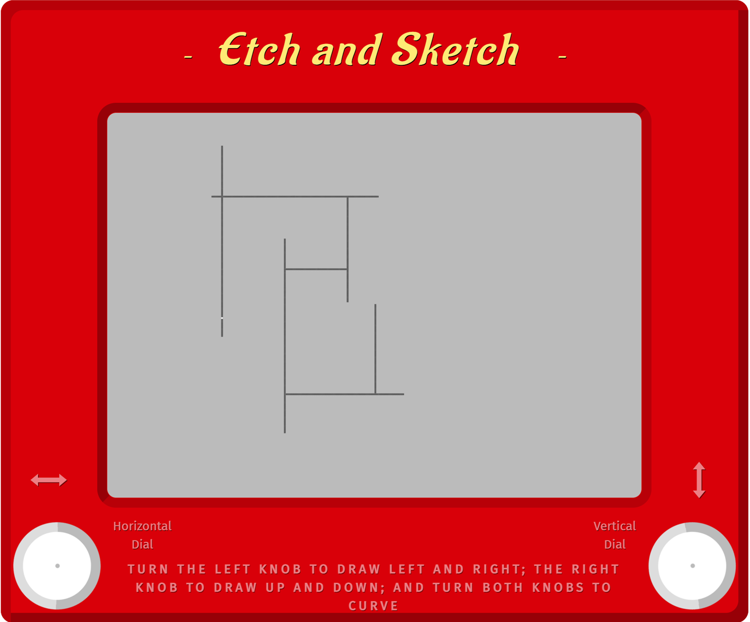
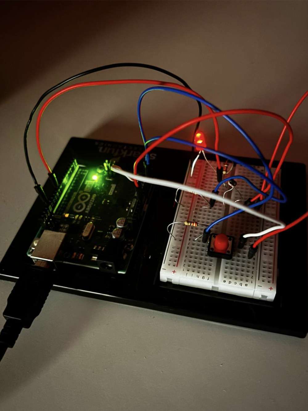
“Sketch and Switch” is a modern take on the Etch-A-Sketch, but with a twist, where the user can draw with random colored lines with mechanical knobs, as this version uses Arduino hardware to control a digital canvas through two potentiometers and a button. The potentiometers allow left/right and up/down movement of the drawing point, and a button press toggles drawing mode while randomly altering the line’s color and thickness.
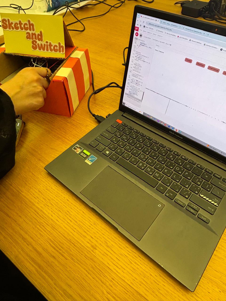
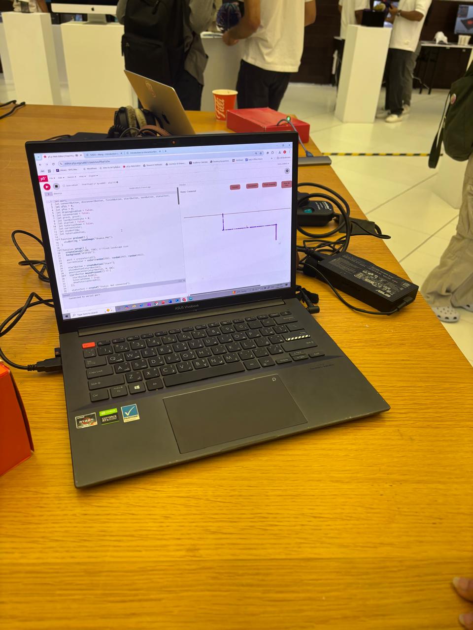
Project Interaction
Video interaction: https://drive.google.com/file/d/1h1HtV-_-JUEKgieFiu1-NDM2Pb2Thfwr/view?usp=sharing
Interaction Design
Users interact with two potentiometers and a button:
-
- Left Potentiometer: Controls horizontal (X-axis) movement.
- Right Potentiometer: Controls vertical (Y-axis) movement.
- Button: Toggles drawing mode and changes the drawing color randomly.
Arduino Code
const int potX = A0;         // Potentiometer for horizontal movement
const int potY = A1;         // Potentiometer for vertical movement
const int buttonPin = 2;     // Pushbutton for toggling draw mode

int lastButtonState = HIGH;
unsigned long lastDebounceTime = 0;      // Timestamp of last button state change
unsigned long debounceDelay = 20;        // Debounce time to avoid false triggers

void setup() {
  Serial.begin(115200);
  pinMode(buttonPin, INPUT_PULLUP);
}

void loop() {
  int xVal = analogRead(potX);           // Read horizontal potentiometer value
  int yVal = analogRead(potY);           // Read vertical potentiometer value

  int reading = digitalRead(buttonPin);
  int btnState = LOW;                    // Default button state to not pressed

  if (reading != lastButtonState) {
    lastDebounceTime = millis();
  }

  if ((millis() - lastDebounceTime) > debounceDelay) {
    btnState = (reading == LOW) ? 1 : 0;  // Set button state (pressed = 1)
  }

  lastButtonState = reading;

  // Send formatted data: x, y, buttonState
  Serial.print(xVal);
  Serial.print(",");
  Serial.print(yVal);
  Serial.print(",");
  Serial.println(btnState);

  delay(20); // Small delay to reduce serial flooding
}
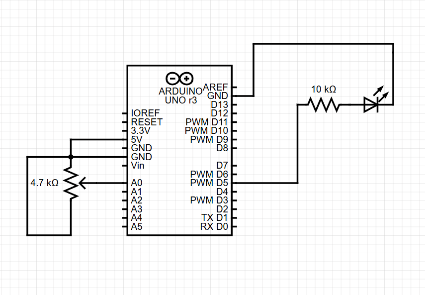
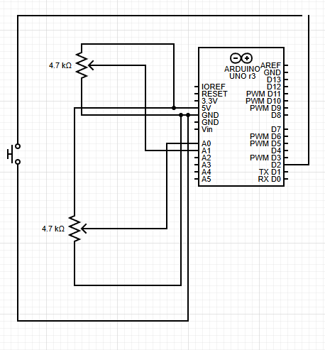
Circuit Schematic
p5.js Code
let port;
let connectButton, disconnectButton, finishButton, startButton, saveButton, statusText;
let xPos = 0;
let yPos = 0;
let drawingEnabled = false;
let isConnected = false;
let prevX, prevY;
let lastButtonState = 0;
let started = false;
let tutorialShown = false;
let currentColor;
let studentImg;
let tutorialButton;

function preload() {
  studentImg = loadImage("Shamsa.PNG"); // preload image for the intro screen
}

function setup() {
  createCanvas(1280, 720); // fixed landscape canvas size
  background("#F5F5DC");

  port = createSerial(); // setup WebSerial port
  currentColor = color(random(255), random(255), random(255)); // initial random color

  // Setup start screen
  startButton = createButton("Start");
  styleButton(startButton);
  positionCenter(startButton, 0, 60);
  startButton.mousePressed(() => {
    startButton.hide();
    tutorialShown = true;
    showTutorialScreen(); // go to tutorial screen before drawing
  });

  statusText = createP("Status: Not connected");
  statusText.position(10, 10);
  statusText.hide(); // hidden until drawing mode begins
}

function styleButton(btn) {
  // Apply consistent style to all buttons
  btn.style("background-color", "#CF877D");
  btn.style("color", "black");
  btn.style("border-radius", "10px");
  btn.style("padding", "10px 15px");
  btn.style("font-size", "14px");
  btn.style("border", "none");
}

function positionCenter(btn, offsetX, offsetY) {
  // Center button horizontally/vertically with optional offset
  btn.position((width - btn.size().width) / 2 + offsetX, (height - btn.size().height) / 2 + offsetY);
}

function showTutorialScreen() {
  clear();
  background("#F5F5DC");

  // Instructions and disclaimer
  textAlign(CENTER);
  fill("#a8423d");
  textSize(32);
  text("Welcome to Sketch & Switch!", width / 2, 80);

  textSize(20);
  fill(0);
  text(
    "Disclaimer:\nThe blue knobs may be difficult at first, so twist them slowly and gently.\n" +
    "The one on the right moves ↑↓, and the one on the left moves ←→",
    width / 2, 160
  );

  text(
    "Instructions:\n1. Press 'Connect' to connect to your drawing device\n2. Twist knobs to move\n" +
    "3. Press the button on the board to change color (it will be randomized)\n" +
    "4. When finishing the drawing, click 'Finish Drawing' to clear it,\n" +
    "   or click 'Save as PNG' to download your art.\n\n Tip: Clockwise = ↑ or →, CounterClockwise = ↓ or ←",
    width / 2, 320
  );

  // Begin actual drawing
  tutorialButton = createButton("Start Drawing");
  styleButton(tutorialButton);
  tutorialButton.position(width / 2 - 70, height - 100);
  tutorialButton.mousePressed(() => {
    tutorialButton.remove();
    clear();
    background(255);
    started = true;
    setupDrawingUI(); // load UI controls for drawing
  });
}

function setupDrawingUI() {
  // Create control buttons
  connectButton = createButton("Connect");
  connectButton.mousePressed(() => {
    if (!port.opened()) {
      port.open("Arduino", 115200); // open WebSerial at 115200 baud
    }
  });
  styleButton(connectButton);

  disconnectButton = createButton("Disconnect");
  disconnectButton.mousePressed(() => {
    if (port.opened()) {
      port.close(); // safely close serial port
    }
  });
  styleButton(disconnectButton);

  finishButton = createButton("Finish Drawing");
  finishButton.mousePressed(() => {
    background(255); // clear canvas
    drawingEnabled = false;
  });
  styleButton(finishButton);

  saveButton = createButton("Save as PNG");
  saveButton.mousePressed(() => {
    saveCanvas("drawing", "png"); // download current canvas
  });
  styleButton(saveButton);

  positionUI(); // arrange buttons
  statusText.show();
}

function positionUI() {
  // Align control buttons along the top
  let baseX = width / 2 - 250;
  let y = 10;
  connectButton.position(baseX, y);
  disconnectButton.position(baseX + 130, y);
  finishButton.position(baseX + 260, y);
  saveButton.position(baseX + 420, y);
}

function draw() {
  if (!started) {
    // Intro screen only if tutorial not yet shown
    if (!tutorialShown) {
      background("#F5F5DC");
      textAlign(CENTER, CENTER);
      textSize(48);
      fill("#a8423d");
      text("Sketch & Switch!", width / 2, height / 2 - 100);

      textSize(24);
      fill(0);
      text("Press Start to Begin", width / 2, height / 2 - 40);

      imageMode(CENTER);
      image(studentImg, width / 4, height / 2 - 30, studentImg.width / 3, studentImg.height / 3);
    }
    return;
  }

  // Serial data handling (reads only once per frame to prevent lag)
  if (port.opened()) {
    isConnected = true;
    statusText.html("Status: Connected");

    let data = port.readUntil("\n");
    if (data && data.trim().length > 0) {
      processSerial(data.trim()); // pass cleaned data to be handled
    }
  } else {
    isConnected = false;
    statusText.html("Status: Not connected");
  }

  // Draw a small dot when not drawing (cursor)
  if (!drawingEnabled && isConnected) {
    fill(currentColor);
    noStroke();
    ellipse(xPos, yPos, 6, 6);
  }
}

function processSerial(data) {
  // Parse "x,y,button" format from Arduino
  let parts = data.split(",");
  if (parts.length !== 3) return;

  let xVal = int(parts[0]);
  let yVal = int(parts[1]);
  let btn = int(parts[2]);

  if (isNaN(xVal) || isNaN(yVal) || isNaN(btn)) return;

  // Map potentiometer values to canvas dimensions
  xPos = map(xVal, 0, 1023, 0, width);
  yPos = map(yVal, 0, 1023, 0, height);

  // Toggle drawing mode when button is pressed
  if (btn === 1 && lastButtonState === 0) {
    drawingEnabled = !drawingEnabled;
    currentColor = color(random(255), random(255), random(255));
    prevX = xPos;
    prevY = yPos;
  }

  // Draw if in drawing mode
  if (drawingEnabled) {
    stroke(currentColor);
    strokeWeight(2);
    line(prevX, prevY, xPos, yPos);
    prevX = xPos;
    prevY = yPos;
  }

  lastButtonState = btn; // update for debounce
}
Arduino and p5.js Communication
Communication is established via serial connection:
-
- Arduino: Sends comma-separated values (X, Y, ButtonState) at a set interval.
- p5.js: Reads incoming serial data, parses the values, and updates the drawing accordingly.
Highlights
I’m proud of the fact that the push button consistently functions to toggle between the drawing modes of randomized thickness and color. Moreover, with optimal baud rate adjustment and data handling, the potentiometers also function with minimal lag, showing smoother and finger movement.
In addition, the project also has clear on-screen instructions and simple0 controls to allow users across any age range to easily become involved, whether they are experts or complete newbies to physical computing.
Areas for Future Improvement
While Sketch & Switch functions smoothly, there’s still plenty of room to build on its foundations:
-
- Add a feature where it allow users to position the drawing point before enabling drawing mode, giving them more control over line placement.
- Adding a color wheel and thickness slider in the UI so users can manually choose colors and line widths, rather than relying solely on randomness.
- Add an undo button to let users correct mistakes without having to clear the entire canvas.
- Replace the current components with larger potentiometers and a larger push button for improved tactile feedback and easier control.