Raya Tabassum: FINAL PROJECT “Interactive Musical Garden”

Concept: Interactive Musical Garden is an innovative interactive art installation that marries technology with natural aesthetics. It incorporates ultrasonic sensors embedded with 3D-printed transparent roses, allowing each rose to respond to user interaction by lighting up, playing music, and spawning a digital flower on a p5.js canvas. This project aims to create a communal yet personalized musical and visual experience where each interaction contributes to a growing digital garden.

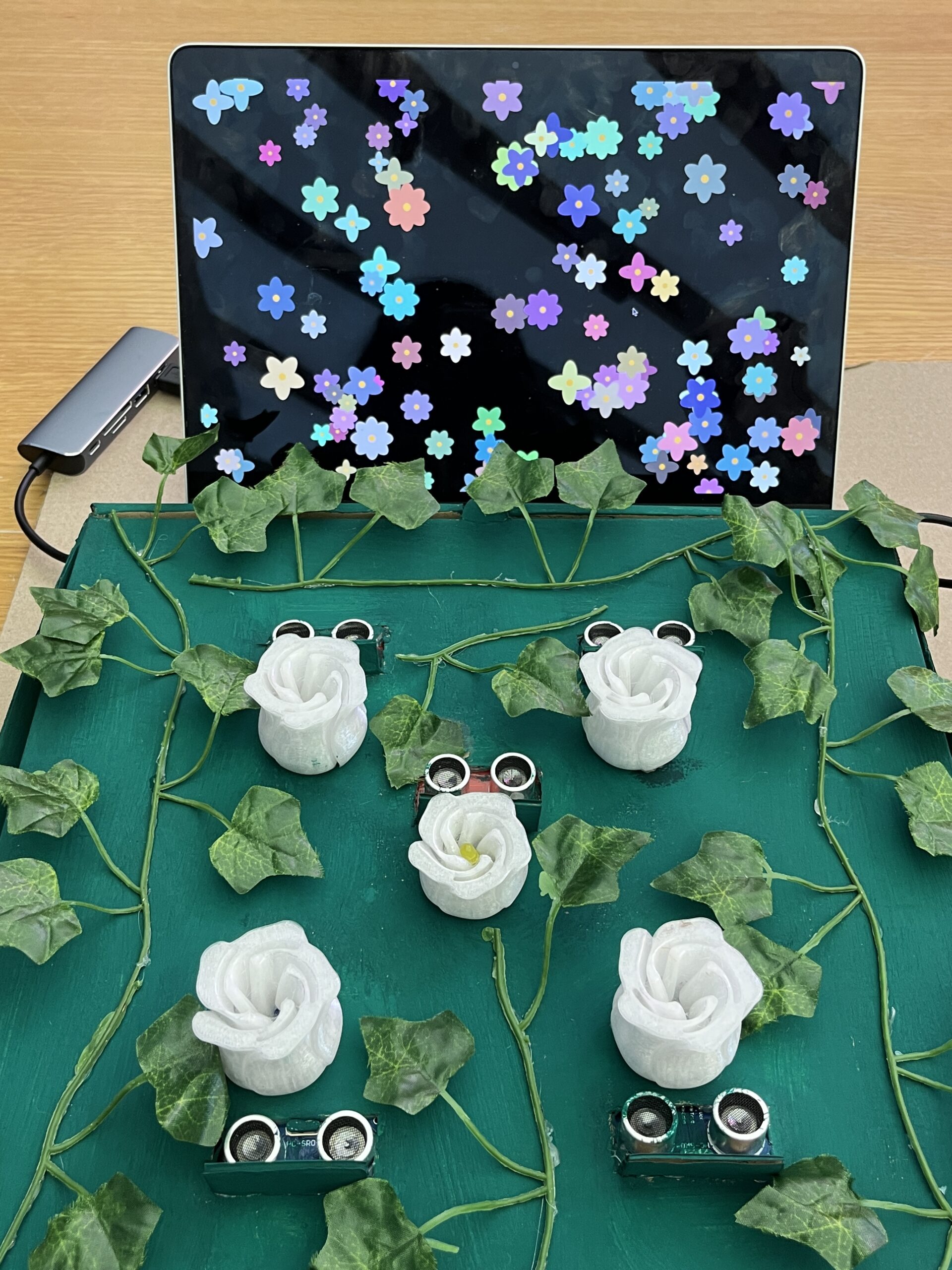
Arduino Code Overview: The Arduino code controls the ultrasonic sensors and LEDs. It reads the distance measurements from the sensors and turns on an LED if an object (e.g., a user’s hand) is detected within a specified range. It also sends a signal to the p5.js application via serial communication when a flower should be spawned.

#include <Arduino.h>

// Define pins for the ultrasonic sensors and LEDs
#define NUM_SENSORS 5
int trigPins[NUM_SENSORS] = {2, 3, 4, 5, 6};
int echoPins[NUM_SENSORS] = {7, 8, 9, 10, 11};
int ledPins[NUM_SENSORS] = {12, 13, A0, A1, A2};

// Function to measure distance
long readDistance(int triggerPin, int echoPin) {
    digitalWrite(triggerPin, LOW);
    delayMicroseconds(2);
    digitalWrite(triggerPin, HIGH);
    delayMicroseconds(10);
    digitalWrite(triggerPin, LOW);
    long duration = pulseIn(echoPin, HIGH);
    return duration * 0.034 / 2; // Convert to distance in cm
}

void setup() {
    Serial.begin(9600);
    for (int i = 0; i < NUM_SENSORS; i++) {
        pinMode(trigPins[i], OUTPUT);
        pinMode(echoPins[i], INPUT);
        pinMode(ledPins[i], OUTPUT);
    }
}

void loop() {
    for (int i = 0; i < NUM_SENSORS; i++) {
        long distance = readDistance(trigPins[i], echoPins[i]);
        if (distance < 20) {
            digitalWrite(ledPins[i], HIGH);
            Serial.print("Bloom ");
            Serial.println(i + 1); // Send sensor number to p5.js
        } else {
            digitalWrite(ledPins[i], LOW);
        }
    }
    delay(100); // Debouncing
}

p5.js Code Overview: The p5.js application runs in a web browser and uses the serial communication data to create flowers on the screen each time a sensor is triggered. It also manages the playback of sound for each interaction.

// Define the Flower class for visual representation
class Flower {
    constructor(x, y) {
        this.x = x;
        this.y = y;
        this.size = 5;
        this.growthRate = random(0.05, 0.2);
        this.fullSize = random(30, 70);
        this.petals = floor(random(4, 9));
        this.petalSize = this.fullSize / 2;
        this.color = [random(100, 255), random(100, 255), random(100, 255)];
    }

    grow() {
        if (this.size < this.fullSize) {
            this.size += this.growthRate;
        }
    }

    show() {
        push();
        translate(this.x, this.y);
        noStroke();
        fill(this.color[0], this.color[1], this.color[2]);
        for (let i = 0; i < this.petals; i++) {
            rotate(TWO_PI / this.petals);
            ellipse(0, this.size / 4, this.petalSize, this.size);
        }
        fill(255, 204, 0);
        ellipse(0, 0, this.size / 4, this.size / 4);
        pop();
    }
}

let flowers = [];
let serial;
let flowerSound;

function preload() {
    flowerSound = loadSound('bells.wav');
}

function setup() {
    let canvas = createCanvas(windowWidth, windowHeight);
    canvas.style('display', 'block');
    background(0);

    serial = new p5.SerialPort();
    serial.open('/dev/tty.usbmodem1101');
    serial.on('data', serialEvent);
}

function draw() {
    background(0);
    flowers.forEach(flower => {
        flower.grow();
        flower.show();
    });
}

function serialEvent() {
    let data = serial.readStringUntil('\n').trim();
    if (data.startsWith("Bloom")) {
        let parts = data.split(" ");
        if (parts.length === 2) {
            let index = parseInt(parts[1]) - 1;
            if (!isNaN(index) && index >= 0 && index < 5) {
                createFlower();
            }
        }
    }
}

function createFlower() {
    let x = random(width);
    let y = random(height);
    let flower = new Flower(x, y);
    flowers.push(flower);
    playSound();
}

function playSound() {
    if (flowerSound.isPlaying()) {
        flowerSound.stop();
    }
    flowerSound.play();
}

function keyPressed() {
    if (key === 'f' || key === 'F') {
        let fs = fullscreen();
        fullscreen(!fs);
    }
}

function windowResized() {
    resizeCanvas(windowWidth, windowHeight);
}

How the Code Works:
Serial Communication: p5.js uses the p5.serialport library to establish a serial connection with the Arduino. This connection allows it to receive data (like sensor triggers) from the Arduino.
Flower Generation: When a “Bloom” command is received via serial (indicating that a sensor was triggered), p5.js generates a digital flower at a random location on the canvas.
Sound Playback: Simultaneously with the flower generation, a sound file is played to provide auditory feedback, making the experience more immersive.

Planning the Interaction Flow:
Detection: A user places their hand over one of the 3D-printed roses.
Sensor Activation: The corresponding ultrasonic sensor detects the presence based on the distance and triggers a response.
LED Feedback: The LED beneath the detected rose lights up, providing immediate visual feedback.
Visual and Auditory Display: The user sees a new flower appearing on the screen and hears a sound, linking their physical interaction with a digital outcome.

Acknowledgements: Special thanks to Stefania for helping me with the idea and the implementation and to my fiancé for helping me setup a beautiful garden using a pizza box 🙂

Raya Tabassum: Final Project User Testing

Here’s my video of user testing:

So till now I incorporated one rose out of 4/5 I’m planning to show. It’s working fine with one so I’m hoping it’d be able to detect all of the roses lighting up and flowers blooming along with it. I’m also hoping to incorporate sound with each rose and have all the samples ready – just have to put it in the code (hope that’d be easy).

Raya Tabassum: Reading Response 7

“Design Meets Disability” provides a rich examination of how design intersects with disability, with a focus on both the historical context and contemporary innovations in the field. It delves into specific examples like eyewear, hearing aids, and prosthetics, and underscores a cultural shift from viewing these items merely as medical aids to considering them as fashion statements and expressions of personal identity.

As someone interested in design, I find the intersection of fashion and functionality particularly fascinating. The way eyewear evolved from a stigmatized medical device to a stylish accessory exemplifies how cultural perceptions of disability and assistive devices can shift dramatically. This shift challenges us to think about other devices in the same light. Could hearing aids or prosthetics become similarly fashionable? This idea encourages a reconsideration of what we define as “normal” and pushes the boundaries of inclusivity in design. From my perspective, embracing design innovation in disability aids not only enhances functionality but also boosts the self-esteem of users. If more designers viewed these aids as opportunities for creative expression, we might see a broader acceptance and desire for these products, much like what happened with eyeglasses.

Raya Tabassum: Final Project Concept & Progress

Finalized Concept for the Project:
“Interactive Musical Garden” is an immersive installation combining technology and nature, designed to create a harmonious interaction between physical and digital realms. The project features a set of 3D-printed roses, each equipped with capacitive touch sensors and LEDs, laid out on a cardboard garden surface to mimic a garden. Interacting with these roses triggers specific musical tones and stimulates the blooming of virtual flowers on a screen, managed via a P5 sketch. This setup aims to explore the symbiotic relationship between touch-based interactions and visual-audio feedback, enhancing the user’s sensory experience through art and technology.

Design and Description of the Arduino Program:

Inputs: The Arduino will use capacitive touch sensors placed beneath each 3D-printed rose. These sensors detect the presence and duration of touch.
Outputs: Corresponding to each sensor, LEDs under the roses light up when a touch is detected. Additionally, the Arduino will send serial data to the P5 sketch indicating which rose was touched.

Interactive Elements:

Visual Outputs: The P5 sketch will display a dynamic garden where each touch on a physical rose causes a new type of flower to bloom at random positions on the screen.
Audio Feedback: Different musical tones are played corresponding to which rose is touched, enhancing the multisensory experience.

User Testing Goals:

Usability: Assess the ease of interaction and intuitiveness of the touch interfaces.
Responsiveness: Measure the system’s responsiveness and the synchronization between physical touches and digital responses.
Aesthetic and Sensory Feedback: Gather feedback on the visual and auditory elements to determine if they effectively enhance the user experience.

To-Dos:

  • Begin assembling the components as per the design (I couldn’t get all the sensors yet because of unavailability but as soon as I get them I’ll try to assemble everything).
  • Complete printing all the roses (I’ve one prototype now but I’d need to replicate another 3).
  • Test the initial versions of the Arduino and P5 code (I’ve written the primary codes, I’ll be repurposing the Virtual Garden p5 assignment I’d completed, and I’ve shortlisted which sound files I want to use).

Raya Tabassum: Serial Communication Project

1. Make something that uses only one sensor on arduino and makes the ellipse in p5 move on the horizontal axis, in the middle of the screen, and nothing on arduino is controlled by p5

For this project, I used a potentiometer connected to the Arduino to send its readings to a p5.js sketch via serial communication. The position of the ellipse on the screen will correspond to the potentiometer’s position.

Arduino Code:

#include <Arduino.h>

void setup() {
  Serial.begin(9600);
}

void loop() {
  int sensorValue = analogRead(A0); // Read the potentiometer
  Serial.println(sensorValue);      // Send the value to the serial port
  delay(50);                        // Delay for stability
}

p5.js Code:

let serial;          
let latestData = 0;  

function setup() {
  createCanvas(640, 360);
  serial = new p5.SerialPort();  
  serial.on('data', gotData);  
  serial.open('/dev/tty.usbmodem11101');  
}

function draw() {
  background(255);
  let sensorValue = map(latestData, 0, 1023, 0, width); 
  ellipse(sensorValue, height / 2, 50, 50); 
}

function gotData() {
  let currentString = serial.readLine(); 
  trim(currentString);                   
  if (!currentString) return;            
  latestData = parseInt(currentString);  
}

2. Make something that controls the LED brightness from p5

To control an LED’s brightness from p5.js sketch, this setup will use a graphical slider in the p5.js sketch to send brightness values to the Arduino, which in turn will adjust the brightness of the LED accordingly.

Arduino Code:

#include 

const int ledPin = 9;  

void setup() {
  pinMode(ledPin, OUTPUT);
  Serial.begin(9600);
}

void loop() {
  if (Serial.available()) {
    int brightness = Serial.parseInt();  
    if (Serial.read() == '\n') {  
      analogWrite(ledPin, brightness);  
    }
  }
}

p5.js Code:

let serial;          
let slider;          

function setup() {
  createCanvas(400, 300);
  serial = new p5.SerialPort();
  serial.on('open', onSerialOpen);  
  serial.on('error', onSerialError);  
  serial.open('/dev/tty.usbmodem11101');  

  //Create a slider from 0 to 255 (LED brightness range)
  slider = createSlider(0, 255, 127);
  slider.position(10, 10);
  slider.style('width', '380px');
}

function draw() {
  background(102);
  let val = slider.value();  
  serial.write(val + '\n');  

  fill(255);
  noStroke();
  text("LED Brightness: " + val, 10, 50);
}

function onSerialOpen() {
  console.log('Serial Port is open');
}

function onSerialError(err) {
  console.log('Something went wrong with the serial port. ' + err);
}

3. Take the gravity wind example and make it so every time the ball bounces one led lights up and then turns off, and you can control the wind from one analog sensor

For this, the wind force is controlled by a potentiometer connected to the Arduino, allowing the user to influence the ball’s horizontal movement by adjusting the potentiometer. And every time the ball bounces off the bottom of the canvas, an LED connected to the Arduino lights up briefly as a visual indicator of the bounce.

Arduino Code:

#include 

const int ledPin = 13;  
const int potPin = A0;  
void setup() {
  pinMode(ledPin, OUTPUT);
  Serial.begin(9600);
}

void loop() {
  int potValue = analogRead(potPin); 
  Serial.println(potValue);          

  if (Serial.available()) {
    char command = Serial.read(); 
    if (command == '1') {
      digitalWrite(ledPin, HIGH); 
      delay(100);                 
      digitalWrite(ledPin, LOW);  
    }
  }
  delay(10); 
}

p5.js Code:

let serial;
let position, velocity, acceleration, gravity;
let wind = 0;
let drag = 0.99;
let mass = 50;

function setup() {
  createCanvas(640, 360);
  serial = new p5.SerialPort();
  serial.on('data', serialEvent);  
  serial.open('/dev/tty.usbmodem11101'); 

  position = createVector(width / 2, 50);
  velocity = createVector(0, 0);
  acceleration = createVector(0, 0);
  gravity = createVector(0, 0.1 * mass);
}

function draw() {
  background(220);
  applyForce(createVector(wind, 0));  
  applyForce(gravity);
  velocity.add(acceleration);
  velocity.mult(drag);
  position.add(velocity);
  acceleration.mult(0);
  ellipse(position.x, position.y, mass, mass);

  if (position.y >= height - mass / 2) {
    velocity.y *= -0.9;  
    position.y = height - mass / 2;
    serial.write('1\n');  
  } else {
    serial.write('0\n');
  }
}

function applyForce(force) {
  let f = p5.Vector.div(force, mass);
  acceleration.add(f);
}

function serialEvent() {
  let data = serial.readStringUntil('\n').trim();
  if (data !== '') {
    let analogVal = int(data);  // Convert the received string to an integer
    wind = map(analogVal, 0, 1023, -5, 5);  // Map the value to a suitable range for wind
  }
}

Challenges:

As I had to do this solo while other people did in groups, I had some disadvantages of course – by not having another perspective of “why’s this not working”.

The first one was rather easy, thought I’m not sure if we’re supposed to show the values on the serial monitor in the video. The second one was quite tricky for me at first – I had taken a different approach where the brightness of the LED was supposed to increase while I move the cursor horizontally on screen from left to right with a ball on screen which when white the LED would turn off and when getting filled with darker shades the brightness of the LED will also increase. But that wasn’t working well as the LED would turn on and off randomly so I took the slider approach instead which was better and clearer to see.

For the third one, as it took input from p5 to show output to Arduino and vice versa – it took a bit of understanding to implement it. First I did one where the ball bounces vertically and the LED will turn on and off with every bounce – as instructed. And you could push the ball to either left or right using the potentiometer. But the one I submitted I found it better – it can bounce towards left or right depending on which side you turn the potentiometer – even if it starts at one side you can change the way while it’s bouncing and the LED also works fine. Overall, it was a great experience doing it by myself to learn better about serial communication.

Raya Tabassum: Reading Response 6

Bret Victor’s “A Brief Rant on the Future of Interaction Design” raises some provocative questions about the trajectory of technology design. Why are we limiting ourselves to interactions with technology through mere touches on glass, when the human body has such a wide range of expressive capabilities? Victor challenges us to consider: What if we could design interactions that fully utilize the intricate ballet of our everyday physical movements? How might we transform our interactions with technology if we thought beyond the glass to harness the full potential of our tactile and kinesthetic intelligence? This essay pushes us to rethink how future technologies might enhance rather than restrict our natural interactions with the world. He champions a more expansive view that utilizes the full range of human capabilities, suggesting that true innovation in interaction design should engage more than just our fingertips — it should involve our entire bodies.
In his follow-up he addresses feedback from his initial “rant.” He clarifies that his critique was meant to highlight the limitations of current interface designs, like “Pictures Under Glass,” and to inspire research into more dynamic, tactile interfaces. He defends the potential of iPads while advocating for more dynamic, tactile mediums for interaction. Victor emphasizes that voice, gesture, and brain interfaces still miss crucial tactile feedback, and points out the dangers of technology that ignores the body’s natural abilities. He calls for technology to adapt to human capabilities, rather than bypass them.

Raya Tabassum: Final Project Primary Concept

I’m thinking of building a “Gesture-Based Musical Interface” for final which will be an interactive system that allows users to create music through hand movements. Combining Arduino’s sensing capabilities with P5.js’s graphical and sound processing, this project will transform physical gestures into a live audio-visual performance. It aims to provide an intuitive way for users to interact with technology and art. I’ll use two ultrasonic sensors to detect the hand movements in X-axis and Y-axis, speakers to output the generated musical notes, and webcam to visualize the movements on p5.

Raya Tabassum: Digital Piano with Percussion Effects

Concept:

The Digital Piano with Percussion Effects is an innovative musical instrument that blends traditional piano elements with modern sensor technology to create a unique and interactive musical experience. This project uses an array of digital push buttons connected to an Arduino board to simulate a piano keyboard, where 8 different buttons trigger 8 distinct musical notes (‘C D E F G A B C#’ or ‘Sa Re Ga Ma Pa Dha Ni Sa’). In addition to the keyboard, the instrument incorporates an ultrasonic distance sensor, which introduces a dynamic layer of percussion sounds. These sounds vary depending on the distance of the player’s hand. Furthermore, a potentiometer is integrated to alter the pitch of the notes dynamically, offering the ability to manipulate the sound palette expressively.

Components Used:

  • Arduino Uno
  • Breadboard (x2)
  • Jumper Wires
  • Piezo Buzzer (x2)
  • Push Buttons (x8)
  • Potentiometer
  • 10k ohm resistors (x8)
  • Ultrasonic Sensor

Video:

Code:

int buzzerPin = 12;
int buzzer2 = 13;
int potPin = A0;
int keys[] = {2, 3, 4, 5, 6, 7, 8, 9};
// Frequencies for notes (C4 to C5)
int notes[] = {262, 294, 330, 349, 392, 440, 494, 523}; 
int trigPin = 10;
int echoPin = 11;
int bassDrum = 200; 
int snare = 250; 
int hiHat = 300;


void setup() {
  pinMode(buzzerPin, OUTPUT);
  pinMode(buzzer2,OUTPUT);
  pinMode(2,INPUT);
  pinMode(3,INPUT);
  pinMode(4,INPUT);
  pinMode(5,INPUT);
  pinMode(6,INPUT);
  pinMode(7,INPUT);
  pinMode(8,INPUT);
  pinMode(9,INPUT);
  pinMode(trigPin, OUTPUT);
  pinMode(echoPin, INPUT);
  Serial.begin(9600);
}

void loop() {
  int potValue = analogRead(potPin);
  int volume = map(potValue, 0, 1023, 0, 255); // Map the potentiometer value to a volume range

  // Measure distance using the ultrasonic sensor
  digitalWrite(trigPin, LOW);
  delayMicroseconds(2);
  digitalWrite(trigPin, HIGH);
  delayMicroseconds(10);
  digitalWrite(trigPin, LOW);
  long duration = pulseIn(echoPin, HIGH);
  int distance = duration * 0.034 / 2; // Calculate the distance

  Serial.print(distance);
  Serial.println(" cm");


  bool isAnyButtonPressed = false;
  for (int i = 0; i < 8; i++) {
    int modifiedNote = map(potValue, 0, 1023, notes[i] / 2, notes[i] * 2);
      if (digitalRead(keys[i]) == HIGH) {
          tone(buzzerPin, modifiedNote, 100);
          isAnyButtonPressed = true;
          break; // Stop the loop once a button is found pressed
      }
  }

  if (!isAnyButtonPressed) {
    noTone(buzzerPin);
  }
  if (distance < 10) {
    tone(buzzer2, bassDrum, 100);
  } else if (distance >= 10 && distance < 20) {
    tone(buzzer2, snare, 100);
  } else if (distance >= 20 && distance < 30) {
    tone(buzzer2, hiHat, 100);
  } else {
    noTone(buzzer2);
  }
    delay(100);
}

In the loop, the program first reads the potentiometer value and uses it to modify the frequency of the piano notes. Depending on the button pressed, it plays a modified note frequency. If no buttons are pressed, it stops any ongoing tone. Depending on the distance detected, it chooses a percussion sound to play, simulating a drum kit with different sounds for different ranges.

Work Process and Challenges: 

For this assignment I was paired up with Snehil. We both worked together to brainstorm the primary idea. First we only had the concept to build the digital piano with push buttons and then we combined the ultrasonic sensor to measure distance and make the percussion sounds to level up the musical instrument. For further improvement Snehil made the potentiometer work to change the pitch of the notes. We were first having trouble to make the ‘for loop’ work for the push buttons to make sound. We were also at first using only one piezzo for the whole instrument and the piano wasn’t working then. So we had to troubleshoot many times to fix those problems.

Final instrument with the potentiometer working:

Raya Tabassum: Reading Response 5

Tom Igoe’s reflections on recurring themes in physical computing projects highlight a vibrant field where creativity and technology meet. He encourages embracing projects even if they seem “done” because each iteration can bring new insights and innovations. From theremin-like instruments, which challenge creators to add meaningful physical interactions, to gloves and video mirrors that mix simplicity with potential for deeper engagement, these themes showcase the dynamic range of physical computing. It’s a call to think differently about what might seem mundane or overdone and to find one’s voice within well-trodden paths. This deeper engagement with the familiar challenges us to discover the unseen potentials in everyday ideas.

The other article by him named “Making Interactive Art: Set the Stage, Then Shut Up and Listen,” highlights a fundamental shift required for artists transitioning into interactive art. He stresses the importance of allowing the audience to engage and interact with the artwork without preconceived notions influenced by the artist’s own explanations. This approach champions a more open-ended exploration where the viewer’s personal experience and interpretation are paramount. This concept connects seamlessly with his views in “Physical Computing’s Greatest Hits (and misses),” where he encourages embracing well-worn themes with fresh perspectives. Both writings emphasize the creative potential in letting go of control—whether it’s about reinterpreting common project themes or allowing interactive artworks to speak for themselves through audience interaction.

Raya Tabassum: Emotional Room Temperature Indicator

Concept: This project combines analog and digital inputs to control LEDs in an innovative way. It’s an “Emotional Room Temperature Indicator”, which uses temperature data and user input to reflect the room’s “mood” with light.

Components Used:

  • Arduino Uno
  • TMP36 Temperature Sensor (Analog Sensor)
  • Push-button switch (Digital Sensor)
  • Standard LED (Digital LED)
  • RGB LED (Analog LED)
  • 220-ohm resistors for LEDs
  • 10k-ohm resistor for the button switch
  • Breadboard
  • Jumper wires

Implementation: I made a reel with description and uploaded as a YouTube shorts embedded below:

Programming:

#define LED_PIN 3
#define BUTTON_PIN 7
int redPin = 9; 
int greenPin = 10; 
int bluePin = 11;
int sensor = A0;

byte lastButtonState = LOW;
byte ledState = LOW;

unsigned long debounceDuration = 50; // millis
unsigned long lastTimeButtonStateChanged = 0;

void setup() {
  pinMode(LED_PIN, OUTPUT);
  pinMode(BUTTON_PIN, INPUT);
  pinMode(redPin, OUTPUT); 
  pinMode(greenPin, OUTPUT); 
  pinMode(bluePin, OUTPUT); 
  pinMode(sensor, INPUT);  // Reading sensor data

  Serial.begin(9600);  // Initialize serial communication at 9600 bits per second
}

int givetemp() {
  int reading = analogRead(sensor);
  float voltage = reading * 5.0 / 1024.0;
  float temperatureC = (voltage - 0.5) * 100;
  Serial.print(voltage); 
  Serial.print(" volts  -  ");
  Serial.print(temperatureC); 
  Serial.println(" degrees C  -  ");
  return (int)temperatureC;  // Convert float temperature to int before returning
}

void loop() {
  int currentTemp = givetemp();  // Call once and use the result multiple times

  if (currentTemp >= 20 && currentTemp <= 30) {
    digitalWrite(greenPin, HIGH);
    digitalWrite(bluePin, LOW);
    digitalWrite(redPin, LOW);
  } else if (currentTemp < 20) {
    digitalWrite(greenPin, LOW);
    digitalWrite(bluePin, HIGH);
    digitalWrite(redPin, LOW);
  } else if (currentTemp > 30) {
    digitalWrite(greenPin, LOW);
    digitalWrite(bluePin, LOW);
    digitalWrite(redPin, HIGH);
  }

  if (millis() - lastTimeButtonStateChanged > debounceDuration) {
    byte buttonState = digitalRead(BUTTON_PIN);
    if (buttonState != lastButtonState) {
      lastTimeButtonStateChanged = millis();
      lastButtonState = buttonState;
      if (buttonState == HIGH) {  // Assumes active HIGH button
        ledState = !ledState;  // Toggle the state
        digitalWrite(LED_PIN, ledState);
      }
    }
  }
}

Actual temperature of the room:

The TMP36 senses the room temperature. Depending on the “comfort” range (set here as 20°C to 30°C), the RGB LED changes colors — blue for cool, red for hot, and green for just right.
The push-button allows the user to set the mood of the room. When pressed, the standard yellow LED lights up to acknowledge that the room is at a comfortable temperature, while the RGB LED shows the current temperature-based mood of the room. The user can thus get immediate visual feedback on whether the room’s temperature is within a comfortable range or not.