For my final project, I delved into graphic design, culminating in the creation of a cooking game called “Mansaf Teta.” This game is a symbol of Palestinian culture, centered around the preparation of a traditional dish. Named after the colloquial term for “Grandma’s Mansaf,
” it aims to encapsulate the essence of Palestinian culinary heritage.
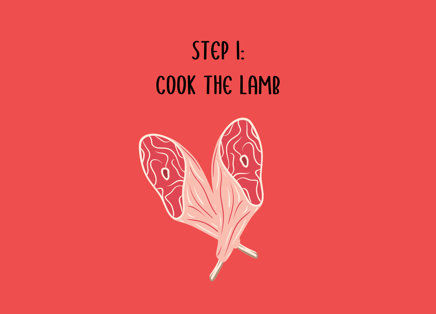
The gameplay involves a series of interactive cooking actions, each tied
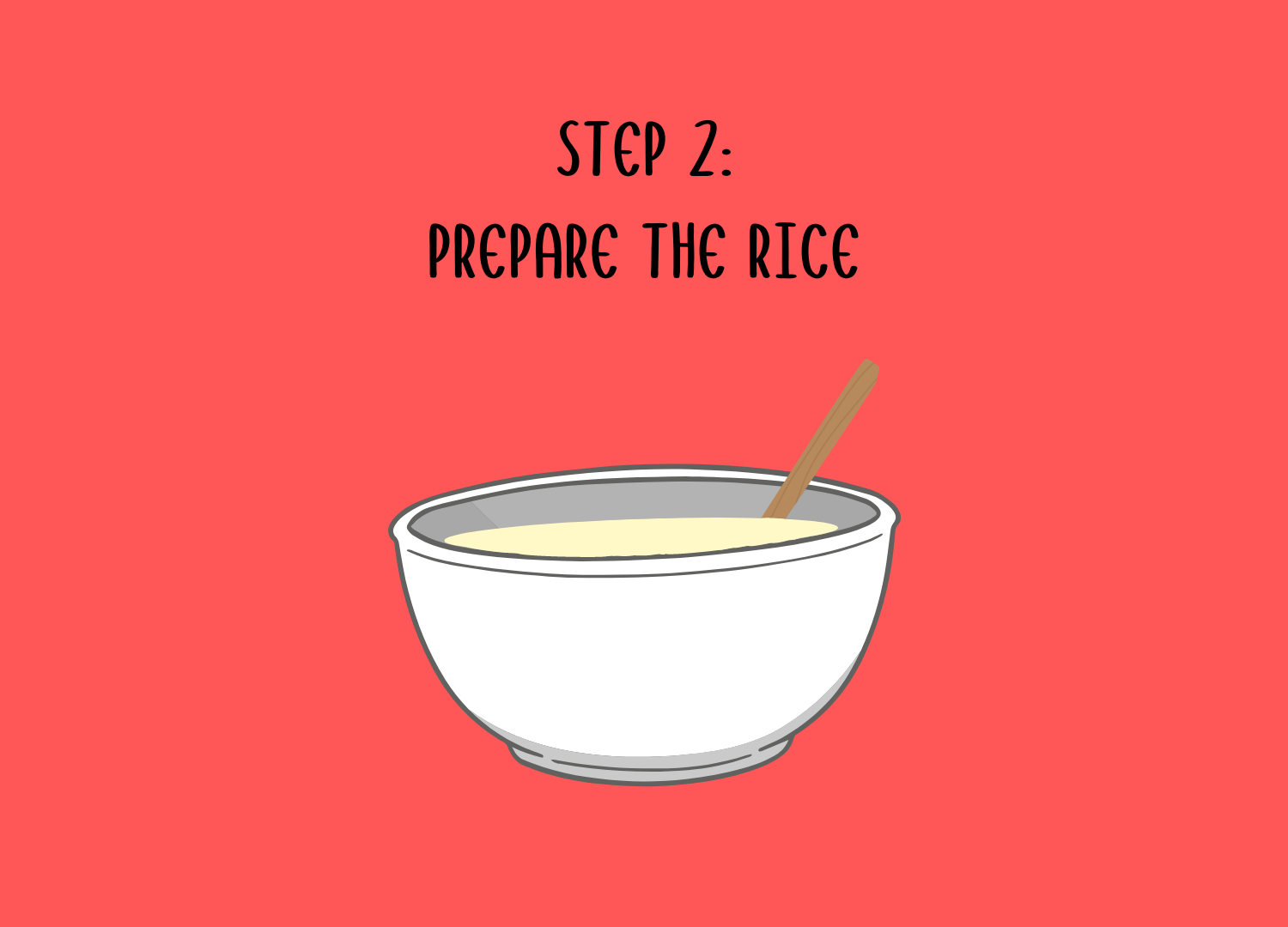
to a physical component controlled by an Arduino board. The first step is cooking the lamb, where players gauge the ideal temperature using a potentiometer. Next, stirring the “laban” (fermented dried yogurt) is simulated using one button to create a stirring motion. Finally, the addition of garnish is triggered by another button, offering players a holistic cooking experience.
My favorite part of the code involves programming the potentiometer and working with images to create a visualization of the stove, shown below:
  if (typeof val1 !== 'undefined') {
    //console.log("val1:", val1);
    // Respond to temperature
    if (val1 < 500) {
      image(toocold, 0, 0, w, h);
      print("checking here: "+valInRangeTime)
      valInRangeTime += deltaTime; // Add the time elapsed since the last frame to the timer
      if (valInRangeTime >= 2000) { // Check if val1 remains in range for more than 3 seconds
        print("going to next image")
        background(next1); // Display the image
        if (mouseIsPressed && mouseIsPressed && mouseX > w / 4 && mouseY > h / 2) {
          gameState = 3; //go to first part
        }
      }
    } else {
      // If val1 goes out of range, reset the timer
      valInRangeTime = 0;
    }
  }
}
Throughout the game-making process, I encountered challenges, especially with establishing a stable serial connection and some game logic. However, with help and guidance from professor and problem-solving skills, I managed to overcome these obstacles and bring my thoughts into a final product.
Looking ahead, I would add more to this project. This includes expanding the variety of sensors on the Arduino board to introduce more nuanced interactions and incorporating additional audio effects to heighten immersion.
Despite these challenges, I take pride in the design and color palette of the game, which I believe enhances the overall experience for players, immersing them in the rich tapestry of Palestinian culinary culture.
So far for my final project I have narrowed down all the ideas I have and created most of the graphics needed, I also started getting into the code and researching tutorials I might need.
I have split my game into 3 stages, each requiring a different sensor: a Potentiometer, a Joystick, and a button. Through these 3 sensors, I will go through the 3 cooking steps to create the final dish. I haven’t gone to much into audio yet but I think I have a general idea.
Below you’ll find the sketch so far (still not much going on) and some of the art I’ve created for now.
For my final project, I am creating a cooking game that engagingly explores Palestinian culture. The dish created is “Mansaf” with the help of “Teta” meaning grandma. The game will consist of several tasks for the dish. The visuals will be on p5 and so will the instructions. I will use several sensors such as a button, joystick, and motion sensor… to complete the cooking tasks. Through audio, visuals, and the hands-on game experience I think the outcome will be very interesting. Of course, some challenges will include p5 and Arduino communication which is why I’ll address them early on.
We connected the Arduino to the P5 sketch using a serial monitor. We did this by downloading a Javascript app from the P5 serial library which acts as an intermediary to allow p5 to access hardware via serial port: available here. This has both access to the javascript browser and connected Arduino. The code below is responsible for declaring variables, handling serial communication (events such as (connection, port listing, data reception, errors, port opening, and closing.), and storing data. To complete the connection we used the code below:
let serial;
let latestData = "waiting for data";
let ellipseX; // Variable to store the x-coordinate of the ellipse

function setup() {
  createCanvas(400, 400);

  serial = new p5.SerialPort();

  serial.list();
  serial.open("/dev/tty.usbmodem101");

  serial.on('connected', serverConnected);
  serial.on('list', gotList);
  serial.on('data', gotData);
  serial.on('error', gotError);
  serial.on('open', gotOpen);
  serial.on('close', gotClose);
}

function serverConnected() {
  print("Connected to Server");
}

function gotList(thelist) {
  print("List of Serial Ports:");
  for (let i = 0; i < thelist.length; i++) {
    print(i + " " + thelist[i]);
  }
}

function gotOpen() {
  print("Serial Port is Open");
}

function gotClose() {
  print("Serial Port is Closed");
  latestData = "Serial Port is Closed";
}

function gotError(theerror) {
  print(theerror);
}
function gotData() {
let currentString = serial.readLine();
trim(currentString);
if (!currentString) return;
console.log(currentString);
latestData = currentString;
}
The x-coordinate of the ellipse is specified by ellipseX, which is updated based on the sensor data in the gotData() function. This allows the ellipse to move horizontally across the canvas based on the sensor readings.
 // Update the x-coordinate of the ellipse based on the sensor data
  ellipseX = map(parseInt(latestData), 0, 1023, 0, width);
}

function draw() {
  background(255);
  fill(0);
  // Draw the ellipse at the middle of the screen with dynamic x-coordinate
  ellipse(ellipseX, height/2, 50, 50);
}
Demo:
Task 2: Use p5 to change LED brightness.
et rVal = 0;
let alpha = 255;
let upArrow = 0;
let downArrow = 0;


function setup() {
  createCanvas(640, 480);
  textSize(18);

  // Replaced Space bar with an actual Button for Serial Connection c
  const connectButton = createButton('Connect to Serial');
  connectButton.position(10, height + 30);
  connectButton.mousePressed(setUpSerial); // Call setUpSerial when the button is pressed
}

function draw() {
  background(map(rVal, 0, 1023, 0, 255), 255, 255);
  fill(255, 0, 255, map(alpha, 0, 1023, 0, 255));

  if (serialActive) {
    text("Connected", 20, 30);
    let message = upArrow + "," + downArrow + "\n";
    writeSerial(message);
  } else {
    text("Press 'Connect to Serial' button", 20, 30);
  }

  text('rVal = ' + str(rVal), 20, 50);
  text('alpha = ' + str(alpha), 20, 70);
}

// Decided on keyPressed as it is more straight forward

// Up Arrow Key turns the light on
function keyPressed() {
  if (keyCode === UP_ARROW) {
    upArrow = 1;
  } else if (keyCode === DOWN_ARROW) {
    downArrow = 1;
  }
}

// Down Key turns the light off
function keyReleased() {
  if (keyCode === UP_ARROW) {
    upArrow = 0;
  } else if (keyCode === DOWN_ARROW) {
    downArrow = 0;
  }
}


// This function will be called by the web-serial library
// with each new *line* of data. The serial library reads
// the data until the newline and then gives it to us through
// this callback function
function readSerial(data) {
  ////////////////////////////////////
  //READ FROM ARDUINO HERE
  ////////////////////////////////////

  if (data != null) {
    // make sure there is actually a message
    // split the message
    let fromArduino = split(trim(data), ",");
    // if the right length, then proceed
    if (fromArduino.length == 2) {
      // only store values here
      // do everything with those values in the main draw loop

      // We take the string we get from Arduino and explicitly
      // convert it to a number by using int()
      // e.g. "103" becomes 103
      rVal = int(fromArduino[0]);
      alpha = int(fromArduino[1]);
    }

    //////////////////////////////////
    //SEND TO ARDUINO HERE (handshake)
    //////////////////////////////////
    let sendToArduino = left + "," + right + "\n";
    writeSerial(sendToArduino);
  }
}
Demo:
Task 3:
Code Snippet:
if (!bounced) {
       bounced = true; // Update bounce state
     } else {
       bounced = false; // Reset bounce state
     }
   } else {
     ledState = 0;
   }
The Brief Rant is a thought out argument for changing our perspective towards our current approach to interaction design and calling the need for other mediums. It focuses on the limits of our current technology and the implications it has on us.
The analogy between kid’s book depriving adults of the complexity of english vocab same goes to touchscreens to restricting interaction design and our capabilities.
In considering another real-world example, my mind goes to VR and AR. Although these technologies have advanced considerably in the past couple of years, there’s still lots of room for growth in terms of interaction design. Picture this: VR systems could undergo enhancement with haptic feedback technology, where it would enbale more immersion.
The other reading also highlights how adeptly we use our hands in everyday tasks, like opening jars and making sandwiches, contrasting this natural interaction with the detached experience of using flat screens. It questions why we settle for interfaces that don’t harness the richness of human touch and manipulation. The author is calling for a interactive design movement that I do see coming in the next couple years hopefully!
For this week’s assignment Sarah and I created a DJ set! The set is built using two potentiometers, a digital switch, a piezo buzzer, servo motors, and two LEDs (for visual feedback). When connected to power, the set produces a melody that the player (DJ) can manipulate by using the first potentiometer (which controls the pitch) and the second potentiometer (which controls the tempo). The red LED blinks in sync with the tempo set by the second potentiometer. The yellow LED’s brightness is proportional to the pitch (the higher the pitch, the higher the brightness). The servo motor resembles the turntables on an actual DJ set. You can activate it by pressing the digital switch. Upon activation, the servo motor will rotate at a speed equivalent to the beat’s tempo.
Implementation
Effectively, the DJ set plays a sequence of notes in succession, stored in a global 2D array, whose pitch class and the tempo of the beat are controlled by the potentiometers. In switching successively between tempos and pitch classes, the player generates different tunes and overall musical moods. The player can also switch on the servo motor, whose position incrementally increases at the same rate set by the tempo the player chose. We utilize two Arduinos, one controlling the sound manipulation between different tempos and pitches using the potentiometers (as well as the LED) and the other controlling the servo motor via a switch. The first Arduino sender program sends the position of the servo motor at time intervals corresponding to the current rate set by the tempo, using the Inter-Integrated Circuit (I2C) Protocol, over to the second Arduino. The receiver program on the second Arduino receives the position and updates the location of the servo, conditional on the button state being on. As the first receiver program also needed to synchronize sound with the blinking of the LEDs, it was essential to extrapolate the concept of blinking without delay to the playing of tones by the buzzer.
Code Snippets
The sender Arduino program reads the two potentiometer values, using the first value to control the pitch (by mapping the value to the range 0-3, corresponding to the range of sequences in the global notes array ) and the second to control the tempo/rate of playing a note. The first value is used to index the 2D array, notes[][], which stores the sequence of notes in different pitches. It also sets the brightness of the yellow LED. The second is used to index the duration[] array, which specifies the rate at which notes are played. The notes in the array notes[potVal1] are played in succession, with the next note in the sequence playing if the specified duration has passed. The state of the red LED is updated to blink according to the rate of the current melody being played. Finally, the position of the servo motor is also updated and sent to the second Arduino program.
note++; // cycle through the sequence
if (note >= 5) {
note = 0; // Reset note index
}
// direction goes forward if position is at 0
if (position <= 0){
servoDir = 1;
}
// direction goes backward if position is at 160
else if (position >= 160){
servoDir = -1;
}
position = (position+servoDir*20)%180;
Wire.beginTransmission(8); // begin transmission to receiver
Wire.write(position); // send over the positon of the servo motor
Wire.endTransmission(); // stop transmitting
Wire.requestFrom(8, 6); // request 6 bytes from receiver device #8
delay(1);
}
}
The receiver Arduino program receives the position from the sender and updates the position if the switch state is set to 1 (the switch has been pressed to turn on the motor). Since the transmission occurs at a rate equivalent to the rate of the music, the motor will move according to the current tempo of the beat.
#include
#include
Servo servo; // initialize servo
int x = 0; // variable storing data transmission
int position = 0; // position of the servo motor
const int switchPin = 7; // switch pin
int buttonState = 0; // current button state
int prevButtonState=0; // previous button state
bool servoMove = false; // keeps track of the switch state
void setup() {
Serial.begin(9600);
pinMode(switchPin, INPUT);
servo.attach(9);
Wire.begin(8);
Wire.onReceive(receiveEvent); // initialize event triggered on receipt of data
Wire.onRequest(requestEvent); // initialize event on being requested data
}
void receiveEvent(int bytes) {
x = Wire.read();
// validate received data
if (x >= 0 && x <= 180) {
position = x; // x directly maps to servo position
}
}
void requestEvent()
{
Wire.write("Hello ");
}
void loop() {
buttonState = digitalRead(switchPin);
// maintain the state of the switch and use to determine if the motor should move
if (buttonState == HIGH && prevButtonState == LOW){
servoMove = !servoMove;
};
// smoothly move the servo towards the desired position
if (servoMove){
if (position != servo.read()) {
if (position > servo.read()) {
servo.write(servo.read() + 1);
} else {
servo.write(servo.read() - 1);
}
delay(1);
};
}
prevButtonState = buttonState;
}
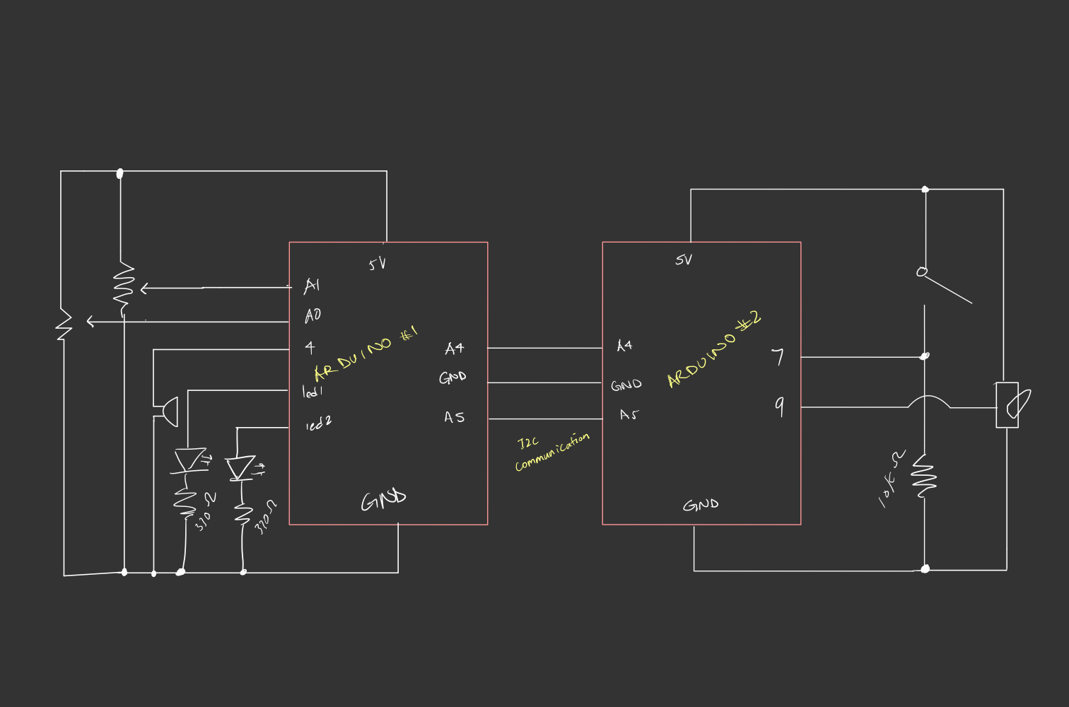
Circuit Schematic
Here’s a schematic of our circuitry: Have a look:
Reflections and Challenges
One of the things we struggled with, largely due to both of us lacking knowledge of musical compositions, is choosing the right sequence of tones that generate a coherent melody. With a combination of trial and error and some research, we found a suitable sequence. We also faced the challenge of one of our LED lights not turning on when we wired the servo motor to the same circuit. Instead of adding a second power source to connect the servo motor to, we opted to utilize I2C since we had an additional Arduino, which proved to be a useful exercise. Overall, we were happy with the final product, but I think it would be nice to extend this project further and give the player a little more creative control as the current setup is quite restrictive in terms of what final melodies the player can generate. For instance, we can have additional buzzers, each producing a different tone, controlled by switches that the users can use to make their own tunes from scratch over a set beat (something like a MIDI controller? ) .
I enjoyed Tigoe’s piece about creating one’s work and then giving it the freedom to be experienced by the public. In the world of interactive art, instead of laying out your art with a manual, it’s about setting the stage and letting the audience be the audience. The main goal here is to direct a play, where the users aren’t told what to think or feel, but are provided with cues and props to navigate their journey. I would 100% prefer having the chance to figure out a task myself than to read a manual or to hear an explanation. It’s like teaching a friend a new card game and saying, “You’ll catch on as we play”. Of course, there will be a trial and error or some confusion but once you’re there, there’s an “ohhh” moment which is my favourite to experience and witness. This reading made me redefine interactivity in my head, it’s almost like figuring out someone’s piece is so stimulating it could in itself be the peak of the experience.
In the second reading, I liked the gloves work. Just as the author voices the importance of listening to the audience’s reactions and responses to the artwork, the discussion about sensor integration in gloves underscores the importance of understanding and responding to the gestures and movements of the user. This parallels the dynamic exchange described in the first reading, where meaning unfolds through the engagement between creator and audience. Overall, both readings focus on the importance of creating interactive experiences that allow users to engage and contribute to the ongoing painting not a final product, whether through exploring an interactive artwork or experimenting with musical expression using gloves.
For my project, I combined a light sensor and a button. The primary concept behind this project was to create an interactive system that responds to both room light levels and user input. The light sensor serves as the eyes of the circuit, detecting changes in the surrounding light environment, while the button enables direct user interaction. One of the main challenges I encountered during the development process was ensuring reliable and accurate responses with the light sensor, especially during the day when everything was lit up. I was thinking about some improvements for this project that could involve adding additional sensors for enhanced functionality, such as temperature or motion sensors, to broaden the range of environmental inputs the circuit can respond to. Overall, this project represents a stepping stone toward creating more sophisticated and responsive sensor-based systems for various applications. I would also work on my creativity in my next project since I was too focused on correcting this part.
For my first Arduino project, I was struggling to find ideas that didn’t involve my hands. I looked around my room, trying to utilize what I already have, and searched for objects that require the use of the body (not hands) to function. Which is when I saw my trash can! The idea was simple, create a circuit that closes when I press down on the trash can to open, and the circuit opens when I remove my foot. I used two foil pieces one stuck to the ground and one to the bottom of the trash can lever, allowing them to intersect and close the circuit when I press down with my foot.
Additionally, the code was pretty straightforward, exactly what we’ve been doing in class:
const int ledPin = 2;
const int foilPin = 3;

void setup() {
  pinMode(ledPin, OUTPUT);
  pinMode(foilPin, INPUT);
  Serial.begin(9600);
}
void loop() {
  int buttonState = digitalRead(foilPin);
  Serial.println(buttonState);
  digitalWrite(ledPin, buttonState);
}
Overall, the code functions by reading the state of the aluminum foil switch and uses that info to control the state of the LED (high/low). When the switch is closed, the LED turns on, and when the switch is open, the LED turns off.
However, I faced several issues during my project:
Error messages from IDE kep showing up, after multiple attempts to troubleshoot (going back and forth between Arduino and IDE) I decided to restart my laptop and Arduino board which ended up solving the issue.
My second issue was that the Led light stays on regardless of the foils touching or not, it’s like the circuit was complete or was not relying on the foils. However, when the foils do touch the led light gets brighter which meant there was an intervention from the foils but not exactly what I’m looking for. I tried to find ways to trouble shoot this but ended up giving up after going back and forth with the code and the board.