final project completion

ORIGINAL CONCEPT

Our original idea was to create a set of friendship touch-lamps, where two lamps would be able to “communicate” with each other with the tap of a finger. Using p5 as our “remote controller”, each party would be able to choose the settings of the light they would like to send, ie. the color and the light patten. We wanted to include wireless communication in our project to stick with the vision that any two users, regardless of time, location, and proximity, would be able to communicate with that special someone through something that was visually compelling, and that the simple act of  sending lights to one another might foster some other type of communication.

IMPLEMENTATION

We believe that we stuck relatively closely to our original proposal, except that due to time and challenges with serial communication, we were not able to achieve this dual communication between two Arduino devices. Hence, although we were not able to achieve interaction from user to user, we were able to achieve interaction between user, lamp, and computer.

The conversation begins with the user interacting with p5. As mentioned above, our p5.js sketch acts as the “controller” of the lamp, providing animations and small game elements that make the programming more interesting. For example, in the second scene of the sketch, the user sees a heart flashing different colors in the center of the screen and is instructed to press the keyboard when the heart flickers to a color of their liking:

Additionally, in the following screen, the sketch displays 3 different light modes to choose from: flicker, wave, and pulse. above those 3 buttons is a corresponding icon that animates that is made to mimic the specific light mode:

Throughout the p5 program, data about the user’s choices are held in three important variables: picker.color, lightMode, and inData. picker.color is an instance variable of the colorPicker class, which was coded to build the flashing heart described above. It is initially set to a null value and is set once the user presses any key to choose their color. Similarly, lightMode is a variable made to hold an integer of 0, 1, or 2 which correspond to flicker, wave, and pulse respectfully. Initially set to a null value, it becomes set when the user presses the flicker, wave, or pulse button in the screen described above. We chose to have lightMode hold an integer, though it is more confusing the the reader, makes it easier to send it as serial data. The inData variable contains the data sent from Arduino through the serial.read() function, and sends a 0 or 1, depending on whether the touch sensor on the lamp has been touched or not touched. This code from Arduino is shown below:

touched = digitalRead(TOUCH_SENSOR); 
  if ((touched == 1) && (sensorState == LOW)) { 
    sensorState = HIGH;
    Serial.write(sensorState); 
  } 

  if ((touched == 0) && (sensorState == HIGH)) { 
    sensorState = LOW; 
  }


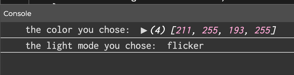
Finally, the conversation shifts between user-computer to user-lamp in the last screen of the p5 program (shown below), where it asks the user to touch the lamp in order to let p5.js know that it is “ready” to send the data to Arduino — “ready” meaning that inData is 1, the lightMode has been set, and picker.color has been set. The code that sends the serial data is also shown below:

if (inData == 1) { 
  // console.log('the color you chose:', colorValue); 
  // console.log('the light mode you chose:', lightMode);
  console.log(inData); 
  let r = red(picker.color); 
  let g = green(picker.color); 
  let b = blue(picker.color);
  
  
  let sendToArduino = r + "," + g + "," + b + "," + lightMode + "\n";
  serial.write(sendToArduino);


Once the data is sent, the “control” of the entire system is handed over to our Arduino code, which is the code that actually displays the lights, completing the final part of the user-lamp conversation. First, after reading the data from p5, it parses the data and organizes it into variables that hold the red, green, and blue color values, as well as the light mode, similar to how it is organized in p5:

while(Serial.available()){
  sensorState = LOW; 
  R = Serial.parseInt();
  G = Serial.parseInt();
  B = Serial.parseInt();
  //lightMode = Serial.read();
  lightMode = Serial.parseInt();

  if(Serial.read() == '\n'){
    Serial.write(0);
  }
}

Then, it uses those variables to create the different light modes (described in more detail in the previous posts):

  if (lightMode == 2){
  // WAVY
  //turn pixels to green one by one with delay between each pixel
  for (int pixel = 0; pixel < NUM_PIXELS; pixel++) { // for each pixel
    NeoPixel.setPixelColor(pixel, NeoPixel.Color(R, G, B)); // it only takes effect if pixels.show() is called
  
    NeoPixel.show();   // send the updated pixel colors to the NeoPixel hardware.
    NeoPixel.clear();
    
    delay(100); // pause between each pixel
  }

  // turn off all pixels for two seconds
  NeoPixel.clear();
  NeoPixel.show(); // send the updated pixel colors to the NeoPixel hardware.
  delay(10);     // off time
}

if (lightMode == 1) { 
// FLICKERING:
  //turn on all pixels to red at the same time for two seconds
  for (int pixel = 0; pixel < NUM_PIXELS; pixel++) { // for each pixel
    NeoPixel.setPixelColor(pixel, NeoPixel.Color(R, G, B)); // it only takes effect if pixels.show() is called
  }
  NeoPixel.show(); // send the updated pixel colors to the NeoPixel hardware.
  delay(1000);     // on time

  // turn off all pixels for two seconds
  NeoPixel.clear();
  NeoPixel.show(); // send the updated pixel colors to the NeoPixel hardware.
  delay(500);     // off time
}

if (lightMode == 3){
  //PULSING   
  uint16_t j;

  for (j = 0; j < 255; j++) {
    for (int pixel= 0; pixel < NUM_PIXELS; pixel++) {
      NeoPixel.setPixelColor(pixel, R, G, B);
      NeoPixel.setBrightness(j); 
    }
    NeoPixel.show();
    delay(20);
  }

  for (j = 255; j > 0; j--) {
    for (int pixel = 0; pixel < NUM_PIXELS; pixel++) {
      NeoPixel.setPixelColor(pixel, R, G, B);
      NeoPixel.setBrightness(j); 
      }
    NeoPixel.show();
    delay(20);
    Serial.println(j);
    }
  delay(100);
  //make sure to set all pixels back to full brightness for the other modes 
   for (int pixel = 0; pixel < NUM_PIXELS; pixel++) { 
    NeoPixel.setBrightness(255); 
  }
}

Note that once the lights are displayed, the data being written out to p5 is that the lamp is not-touched and is ready for the next round of data to be collected from p5. The user has the option to stop there, or can repeat the “cycle” as many times they wish by clicking the “send another” button in p5.

WHAT WE’RE PROUD OF

Something we like about our system that we think enhances the experience is the attention to detail and aesthetic of the p5 sketch. We chose the name “Distance makes the Heart and Glow Fonder” because it is not only a cute play on words, but also keeps with our neon theme. We also wanted all of our text and images to have flickering effect and a glowing effect (reference:  https://www.youtube.com/watch?v=iIWH3IUYHzM) to mimic real life neon signs and lights. Also, we felt that adding animations to the screen that shows the light modes not only made it more visually compelling but more intuitive for the user, given that the instructions of the program are minimal.

Though none of us have much experience with building, we wanted to push ourselves beyond the Arduino board we were given and try our best to make a lamp that didn’t look so obviously “Arduino”. Overall we are very happy with how it turned out, considering the time and resources we had. Everything we used to build it was made out of scrap materials found in the lab, and each part of the lamp is detachable by velcro, making it extremely easy to access the wiring and adjust things if needed.


FUTURE IMPORVEMENTS

In terms of the physical lamp, it would be nice to completely cover the wiring at the bottom with more acrylic panels. Perhaps remaking it using a different glue will also help get rid of the fogging happening on the current model.

In terms of our code, we would like to carry out our initial vision and create two lamps that can communicate with each other, and perhaps even have them communicate wirelessly.


DEMO

Below are some demo videos of our project.

MY PART

Things I contributed to the project:

  • did the main bulk of brainstorming and coming up with the two ideas we proposed in class, in the end went with my second idea (the lamps) as I was receiving little feedback and reciprocation from my partner’s end
  • initiated each time we planned to meet and work on the project
  • wrote 90% of all blog posts. – first post written all by me, second post written mostly by me with except for the sections “The role of Arduino” and “communication”, third blog post I wrote the “solution” section and was the one who came up with the solution and implemented it individually
  • wrote 100% of the p5 sketch
  • wrote all the code that managed the serial communication, in p5 and Arduino with the exception of the parsing integers, wrote the code for the touch sensor
  • with the exception of soldering 3 wires and cutting 2 triangle pieces of acrylic, came up with the design of the lamp and built the entire structure alone
  • was constantly debugging alone in the lab and asking for help from lab assistants, especially when it came to solving the serial communication errors.
  • wrote 100% of this blog post

Week 13 Progress update

OVERVIEW

As of this week, we had some tweaks to the concept of our whole idea. The idea will now center on connecting two people and two lamps to a single computer. This week has been filled with a range of challenges that have put our knowledge of Arduino and p5js to the test. Integrating a touch sensor to send data from Arduino to p5js and collecting and transmitting several bytes of information from p5js to Arduino are some examples of the operations that fall under this category. Among the concept adjustments we made was to use regular wire serial communication between Arduino and p5js rather than relying on the use of a bluetooth module, which would have made the project more interesting.

PROGRESS

At the moment we are struggling with successfully sending RGB values from p5js to Arduino and eventually displaying them on the LED strip. As of now, when we transmit specified color values from p5js to Arduino, they are displayed on the LED strip as intended. However, only the color white is projected on the LED strip when we send any other RGB values. Additionally, the lights do not “cycle” through their respective patterns like they should. For example, when we chose “flicker”, the lights flicker once and remain off, instead of flickering continuously as intended in the Arduino code.  We started by doing a number of comprehensive tests to rule out the possibility that the issue could be with the serial transmission. The only remaining hypotheses for the bugs that we are still investigating are if the problem could be caused by using the jpg color wheel to determine color values or whether there are more mechanisms involving how Arduino interacts with LED strips that we need to comprehend. The below is a compilation of test-related videos:

(lights only showing white and not looping continuously)

(testing the color printed in the console vs the color that appeared to be chosen from the wheel and seeing that they two colors do not match up)

SOLUTION

After several hours of debugging, we found that using an image to pick the color just wasn’t working.  We determined our hypothesis to be correct – that the issue was the values being sent by p5.js.

The mouse position was taking pixels from the original image and it was not being remapped to the resized and re positioned image we had in our code, even after applying the map function and several iterations of repositioning/resizing the image. We believe that the example used ( link ) to create the color picker worked because the image IS the canvas, which is not the case for ours.

We decided on a new way for the user to select the color, which would be by having an object that flashes a different color every few seconds where the user can then press a key to “freeze” the object on the selected color. In our updated sketch, all possible colors have been predetermined by us, though the process of choosing the color is more engaging now.

After making this change, the values sent to Arduino were actually representative of the color that was chosen when pressing a key, and the color that is displayed on the LED’s is now accurate. However, this did not solve the issue of the lights not looping.

final project commitment & progress

CONCEPT

In our last post we had come up with a game for our final project. After some further brainstorming, we thought it would be fun to try something other than a game, considering that this is what we did for our midterms. We thought about making an interactive system that could be experienced by multiple people at the same time. Our idea for the project is now to create a touchable “friendship lamp.” The basic idea is that we will build two lamps using two Arduino boards and LED strips. Each light will be equipped with different settings that can change the light pattern and color. These settings will be able to be manipulated within a program on p5.js, accessed on separate computers by the two users. After one user chooses the settings of their light, they then touch their lamp to send that light to the other user’s lamp. Communication between the two users can be simultaneous and there is no limit to the amount of times they can send each other messages. 

THE ROLE OF P5.js 

The sketch on p5.js will be a simple program with a few screens that allows the user to control the light they will send. They will be able to choose any color from a color wheel, and they will be able to choose from 3 different light modes: flicker, wave, and pulse. The choices made by the user will be stored by the program, and p5 will then send this data to the board of the other person’s lamp. However, data is not sent until some feedback is received from Arduino, explained in detail in the following section. 


THE ROLE OF ARDUINO 

A touch sensor and an LED strip would both be included in the Arduino circuit. When touched, the touch sensor transmits a signal to p5js, enabling p5js to transfer data to the Arduino board. Since p5js will be sending data about the color and pattern that the LED strip should light up in, the arduino board receives this data and turns the light on as requested by the user.


COMMUNICATION

As for the method of communication (serial mode) between the Arduino and p5js, we are still employing wires to transfer data back and forth at the time. However, because the two lamps and users in our original concept must be distanced from one another, we are exploring and, ideally, planning to include Bluetooth modules or, perhaps, an esp32 on our board to help with wireless communication between the two platforms.

PROGRESS 

We knew that we weren’t going to be able to have cross communication between two users without wireless Arduino boards, and that we would not be able to implement the touching aspect without an actual tactile sensor. Hence, our plan for this week was to finalize our idea and begin assembling the different components of the system separately. The p5 program is almost complete, with an exception to the code that will send the data to the wireless Arduino board. The sketch is shown below:

At the end of the program, the console prints out the data that would theoretically be sent to Arduino. Including the color value and the light mode. Also, because we do not have the tactile sensor yet, the light is “sent” figuratively by just pressing any key in the third step. 

For the Arduino component, we built our strips of 10 LED’s for each lamp and connected them to a board and focused on simply creating three different light modes that could be controlled within the Arduino code, separate from p5. The code that demonstrates how the various light modes are used to enable a flicker, wavy, or fading effect on the LED strip is provided below:

void loop() {
  NeoPixel.clear(); // set all pixel colors to 'off'. It only takes effect if pixels.show() is called
  NeoPixel.show();
  // WAVY
  //turn pixels to green one by one with delay between each pixel
  for (int pixel = 0; pixel < NUM_PIXELS; pixel++) { // for each pixel
    NeoPixel.setPixelColor(pixel, NeoPixel.Color(0, 255, 0)); // it only takes effect if pixels.show() is called
    // if(pixel > 0)
    // {
    //   NeoPixel.show();   // send the updated pixel colors to the NeoPixel hardware.
    //   NeoPixel.clear();
    // }
    NeoPixel.show();   // send the updated pixel colors to the NeoPixel hardware.
    NeoPixel.clear();
    
    delay(100); // pause between each pixel
  }
  // turn off all pixels for two seconds
  NeoPixel.clear();
  NeoPixel.show(); // send the updated pixel colors to the NeoPixel hardware.
  delay(2000);     // off time
  // FLICKERING:
  //turn on all pixels to red at the same time for two seconds
  for (int pixel = 0; pixel < NUM_PIXELS; pixel++) { // for each pixel
    NeoPixel.setPixelColor(pixel, NeoPixel.Color(255, 0, 0)); // it only takes effect if pixels.show() is called
  }
  NeoPixel.show(); // send the updated pixel colors to the NeoPixel hardware.
  delay(500);     // on time
  // turn off all pixels for two seconds
  NeoPixel.clear();
  NeoPixel.show(); // send the updated pixel colors to the NeoPixel hardware.
  delay(500);     // off time
  //PULSING
  brighten();
  darken();
}
// 0 to 255
void brighten() {
  uint16_t i, j;
  for (j = 0; j < 255; j++) {
    for (i = 0; i < NeoPixel.numPixels(); i++) {
      NeoPixel.setPixelColor(i, 0, 0, j);
    }
    NeoPixel.show();
    delay(10);
  }
  //delay(100);
}
// 255 to 0
void darken() {
  Serial.begin(9600);
  uint16_t i, j;
  for (j = 255; j > 0; j--) {
    for (i = 0; i < NeoPixel.numPixels(); i++) {
      NeoPixel.setPixelColor(i, 0, 0, j);
    }
    NeoPixel.show();
    delay(10);
    Serial.println(j);
  }
  delay(100);
}


Finally, a demo of the different modes is displayed below:


final project proposal

By: Fuad & Phoebe

INSPIRATION

For our final project, we were interested in making another game, but instead of a more action-based game, one that was a subtle, calming, yet visually pleasing game. We discussed the mobile game I Love Hue, which is a puzzle type game that tasks the player with organizing a grid of tiles of different colors into a gradient. We also discussed the meaning of good interaction design and how to create a system whose parts were meaningful, intentional, and effective.  Something that was simple, with few “gadgets,” and minimalistic but visually pleasing animations were two things we wanted to incorporate. As such, we came up with a “color matching” game.

CONCEPT 

Our color matching game consists of a series of “levels”, where each level displays a two squares side by, one square being the “target” color, and the other being the “test” square that the player must manipulate to match the target color. The player will be able to manipulate the color of the square by turning potentiometers on the Arduino board, each that correspond with the red, green, and blue values of the target color. The player will have a set amount of time to adjust the color of the test square and is scored based on how close the match is to the target color.


What Arduino will do 

As mentioned above, Arduino will provide the means for manipulating the color onscreen. Each potentiometer will be mapped to a value of 0 to 255, corresponding to rgb values. Other than perhaps clicking a key to start the game, the player shouldn’t need to use the keyboard or mouse.

What p5.js will do 

The sketch will provide almost all visuals of the game. However, we thought it would be interesting to include red, green, and blue LED’s on our board, whose brgithness would change according to how close the user was to the values of the target color. Hence, the sketch would also coommunicate back to Arduino, adjusting the brightness of the LED’s.

Connecting Arduino to p5.js: in class exercises

EXERCISE 1

Extending the potentiometer example demoed in class, we created a smiley ball that bounces horizontally across the screen whose velocity was dependent on the value of the potentiometer. Inside our Arduino code, we write the value of the potentiometer as serial output to the p5.js sketch: 

void loop() {
  // put your main code here, to run repeatedly:
  int potentiomenter = analogRead(A0); 
  int mappedPot = map(potentiomenter, 0, 1023, 0, 255); 
  Serial.write(mappedPot); 
  delay(100); 

The corresponding breadboard is shown below: 

[image]

Inside our p5.js sketch, we created our smiley ball by making a simple Circle class with an x and y position and a move() method. The move method() doesn’t change the ball’s y position, as it remains constant along the horizontal axis height/2, but it does update the x position, which is calculated using the variable inData – the value of the potentiometer read from Arduino. A snipped of the code is shown below: 

class Circle {
  constructor(x, y, d) {
    this.x = x;
    this.y = y;
    this.d = d;
  }
  move() {
    if (this.x<=50) {x = 1;}
    else if (this.x>=550) {x =-1;}
    
    let y;
    
    if (inData==undefined) {
      y=0;
    } else {
      y = inData;
    }
     
    this.x+=(y/20)*x;
  }

Finally, a demo of the final product is shown below: 


EXCERCISE 2

We thought that the first exercise was rather bland in terms of visuals, so for this exercise we wanted our p5.js sketch to be more interesting. We made the connection of a sun rising and falling to the brightness of an LED, hence our sketch shows a sun against a mountain landscape that can “rise” and “fall” by pushing the up and down arrow keys. As the sun “rises”, the sky changes to a bright magenta color, and when the sun “falls”, the sky deepens to a dark blue color. We achieved this by having the sun’s y position (also built from the Circle class of Exercise 1) determine the rgb values of the background, as demonstrated in the following code:

function draw() {
  background(300-c.y, 100-c.y, 100+c.y); 
  c.display(); 
  c.move(); 
  
  var rightBrightness = map(c.y, height, 0, 0, 255);
  
  outData = rightBrightness;  // setup the serial output
  serial.write(outData); // write to serial for Arduino to pickup

This seamless gradient effect then corresponds to the brightness of an LED on our Arduino board. 

[image]

The sun’s y position is stored as outData, which is then sent to Arduino. Inside our Arduino code, we map the incoming value to a scale of 0 to 255 and use that value to analog write the LED brightness. A snippet of this code is shown below: 

void loop() {
    if (Serial.available() > 0) { // see if there's incoming serial data
      incomingByte = Serial.read(); // read it
      led2brightness = map(incomingByte, 0, 255, 0, 255); // map the input value to the brightness for second LED
    } else { }
    analogWrite(ledPin, led2brightness); // write the brightness to the led pin 2
    
}


Finally, a demo of the finished product is shown below:


EXERCISE 3 

For the final exercise we were required to incorporate bidirectional serial communication, basically using the arduino to control a p5js sketch, and using changes in the p5js sketch to produce changes to the arduino. On the arduino, we used a distance sensor to affect the change of wind in p5js to make the ball move. On the p5js sketch we programmed it in such a way that everytime the ball bounces an LED lights up depending on the velocity of the ball.

Musical Instrument

OVERVIEW

for this weeks musical instrument project, we created a DJ setup using servo motors and a piezo buzzer. A digital switch controls the piezo buzzer, which cycles through a series of melodies, while two potentiometers control the servo motors. The potentiometer on the left hand side controls the speed at which the arms rotate, while the potentiometer on the right hand side controls how wide the arm sweeps. A demo of the instrument is shown below. 

DESIGN 

Our original idea was that we wanted to create some type of percussion instrument that would play rhythms rather than notes,  since using the buzzers as the main focus of the instrument felt a bit predictable. Interestingly, the sound and movement of the servo motors reminded us of turn tables, and hence our DJ idea was born. We also really liked using potentiometers to control the rhythm of the servo motors, because the twisting motion of the potentiometers felt very intuitive and similar to the actual motion one would use on a turn table. To add more interest, we decided to add on a buzzer that would play “techno” music to make the entire piece have a clear “club” or “house” atmosphere. 

SCHEMATIC

A schematic of our board is shown below:

CODE 

The instrument gets its input through two analog sensors – the potentiometers, and one digital sensor – the button. As mentioned above, the analog sensors control the servo motors, or the turn tables. Inside our program, the value obtained by the potentiometer is stored in a variables sensorValue1 and sensorValue2. The former is then used to control the delay, or how fast the motor arm is sweeping, while the latter controls the degree to which the arm motor sweeps. This is demonstrated in the code below:

for (pos1 = 0; pos1 <= 60 + sensorValue2/20; pos1 += 1) {
... 
    myservo1.write(pos1);              
    myservo2.write(pos1);
    delay(sensorValue1/50);    
}

On the other hand, the digital sensor controls which melody the piezo will play. Our program has an array of 3 different techno melodies (called melodies[], each 16 notes each. We cycle through each melody by defining a variable called melodyState, which ranges from 0-2, corresponding to the length of the melodies[] array, and increments each time the button is clicked. This is demonstrated in the following code:

In the beginning of loop() calculating the melodyState:

int buttonState1 = digitalRead(pushButton1);

 if (buttonState1==HIGH) {
   add = true; 
 }

 if (add) {
   melodyState++;
   add=false;
 }
if (melodyState>=3) melodyState=0;

Using melodyState to index into the melodies[] array:

if (pos1%frequency==0) {
  tone(5, melody[melodyState][melodyCount], length);
  delay(50);
  noTone(5);

  melodyCount++;
  if (melodyCount >=16) { 
    melodyCount = 0; 
  }

CHALLENGES  & IMPROVEMENTS

One of the challenges of this project was the wiring. Because we had so many elements we wanted to incorporate, we did struggle with the circuit getting cut off in certain places where we added new elements. Also, because we used two potentiometers, and one of them was directly connected to 5V, and all other elements were connected to this potentiometer, this meant that when it was turned all the way down, all the power was shut off and the circuit broke. In terms of what we would like to improve, we thought it would be cool to add lights that would flash in correspondence with the melody that was playing, though because our board was already very cluttered, we opted against it. (As shown in the demo, it is a little difficult to maneuver given the tight space). We do, however, think it is worth experimenting with spreading our circuit across multiple breadboards. For example, it would be nice to have the servo motors and potentiometers on one board, and the buzzer and lights on another.  

Analog & Digital

DESIGN

Because I am still unfamiliar with circuit building, what I created for this project is rather simple. Two elements on the board, a digital switch and a light sensor control two LED’s. When the program starts, the lights flicker in an alternating pattern with a starting interval of 500 milliseconds. However, the frequency at which the LED’s flicker is dependent on the light sensor: low levels of light cause the lights to flicker on a larger interval, and high levels of light cause the lights to flicker on a shorter interval. Finally, the switch changes the LED’s from flickering in an alternating pattern to a simultaneous pattern.

MATERIALS 

The materials I used for this project are listed below:

  • 2 LED’s
  • 3 10k Ohm resistors
  • wires
  • switch
  • light sensor

BUILDING THE CIRCUIT 

I began by building a simple 2 LED circuit like we had practiced in class. I then incorporated the switch, and finally I extended it to include the light sensor. A photo of the board is shown below:

CODE 

The most challenging part of this project was getting the button to toggle. In class, we had only worked with buttons that do something once when clicked; however, what I wanted was for the LED’s to maintain a certain pattern from the time the button was pressed to the time it was pressed again. To achieve this, I referenced the Arduino website. Ooutside of the setup() and loop() function, I define variables currentButtonState, previousButtonState, and ledState. The currentButtonState is obtained by reading the input at pin 8, which is where the switch on the board is connected. The ledState is initially set to LOW and is the variable that defines what the LED’s do. In the loop() function, the state of the button is defined by the following if statement:

if (previousButtonState == HIGH && currentButtonState == LOW) { 
  ledState = !ledState; 
  digitalRead(ledState); 
}

This statement essentially says that when the button is pressed, flip the ledState  from HIGH to LOW and vice versa. In separate if statements, I define the behavior of the LED’s, which has to options: flash simultaneously when the ledState is HIGH or flash alternating when the ledState is LOW. The code is shown below:

if (ledState) { 
  digitalWrite(LED1, LOW); 
  delay(interval); 
  digitalWrite(LED1, HIGH); 
  digitalWrite(LED2, HIGH); 
  delay(interval); 
  digitalWrite(LED2, LOW); 
}

if (!ledState) { 
  digitalWrite(LED1, HIGH); 
  delay(interval); 
  digitalWrite(LED1, LOW); 
  digitalWrite(LED2, HIGH); 
  delay(interval); 
  digitalWrite(LED2, LOW); 
}

FINAL PRODUCT

REFLECTIONS

As mentioned above, I find building circuits very challenging, while the coding portion comes more naturally to me. I am relatively comfortable coding in C, so making the transition to using C++ was not too difficult, and I actually had a lot of fun experimenting with the code. I do wish that this project could have been more creative and visually appealing, but I don’t think time allowed. I spent a lot of time taking apart the board and rebuilding the board several times so that I could better understand how the circuit was working.


Touch-less Switch

DESIGN

For this project, I created a touch-less switch that turns on when the user blows a metal ball onto another metal plate. A demo of the switch is shown below:

I wanted my switch to be fun and have a game/challenge aspect to it, and I feel like I satisfied this,  since the person turning on the switch must blow from the right angle and direction to ensure the ball touches the metal plate. Moreover, depending on how hard the user blows, the LED can go from a flickering/flashing light to a constant light, so the harder and more direct the air is blown, the brighter the LED. I also think that this aspect of the switch helps the user better understand how the circuit is working, because they can clearly see (and feel) that when not enough air is applied to the ball, the circuit is very loosely connected and doesn’t work as well.

Originally, I wanted to create a tumble weed made of wire; however, after some experimentation, I realized the shape I had created didn’t roll as well unless the user was blowing extremely hard, so I switched to using something that was perfectly spherical.

MATERIALS

The materials I used to create the switch included:

  • 1 LED
  • 4 wires
  • 1 330 ohm resistor
  • electrical tape
  • duct tape
  • copper tape
  • 1 ping pong ball
  • 1 metal plate
  • scrap block of metal

BUILDING THE SWITCH 

A close up of what my Arduino board looks like is shown below:

I began by building the most elementary circuit that we had worked on in class. For this I used an LED, resistor, and 1 black and red wire each. After completing this, I then added two wires (in white) in the “middle” of the circuit, which I would then use to extend the circuit outside the Arduino board and integrate my touch-less switch.

The next step was building the components of the switch. For the metal ball, I knew I needed something light enough to be able to be moved by someone blowing on it, so I opted for a tin foil covered ping pong ball. The other side of the switch was constructed by duct-taping a metal plate onto a scrap piece of metal. This step was important to ensure that the other end of the switch was heavy enough to not move as the user blew on the metal ball. A close up of the switch is shown below:

Finally, I secured each side of the switch to each of the white wires using some electrical and copper tape. The entire circuit is shown below:


CHALLENGES WITH ADHESIVES

The biggest challenge of this project was honestly attaching the components of the switch to the wires. I experimented a lot with the copper tape, as it had been recommended to me by another student. However, I found that the tape is barely adhesive and not flexible enough to wrap around curved objects like the ping pong ball or thin objects like the head of the wires. On the other hand, the electrical tape, while much more sticky and elastic, didn’t stick very well to metal objects. My solution was to use copper tape as a base layer to stick the wires to the metal ball/plate and then cover it with electrical tape to secure it in place. I found that duct tape worked best on metal, but because it is an insulator, I only used it to attach the metal plate to the scrap metal.

ALTERNATIVE SWITCH 

Finally, one alternative version to this touch-less switch is instead of having the metal plate standing up vertically, having it lay flat on the table. In this way, the user does not need to continuously blow on the ball to keep the light on; instead they need only to blow at the right angle and speed so that the ball rolls on top of the plate.

Midterm Project: final update

THE FINAL PRODUCT  

The link the code on the web editor can be found here here. I have also embedded the sketch below, although the game must be viewed in full screen on Chrome, with the Bookmarks tab hidden. I made this choice to have the canvas size this large so that the user could be fully immersed in the game. Since this isn’t one of those games that’s meant to be played to pass the time, I didn’t want a small canvas size and other tabs to distract from the experience. Of course, headphones with decent sound quality also enhance the experience.


CHANGES & SIMILARITIES FROM THE STORYBOARD 

Overall, the final product is very similar to the storyboard created in last weeks post, although some of the games have been modified. A theme that I wanted to establish from the start was an 80’s arcade aesthetic. The aesthetic is very nostalgic of the gameboy and nintendo games I used to play as a child, and because the game is sort of reflective of my life as an adoptee up until now, I think it is fitting. I wanted there to be lots of pixelated images, saturated colors, and sounds that are reminiscent of old computers. In terms of the story I was telling, I wanted the text to be informative and genuine so as to represent my experiences as authentically as possible, but still very personal  and quirky. I think I accomplished this  quite well.

In terms of the actual games, I did make some changes in the final product. For the first chapter, I felt that the “lost treasure” analogy (explained on the mind map) was difficult to capture and more complex than I anticipated. Instead I decided to make a maze. In the second chapter, I still wanted to express the idea of mixing culture, but due to time constraints, I simplified the game that was intended to be a chasing game, where the blue monster is controlled by the user and the red controlled by the computer. Unfortunately, I was unable to make the red monster move on its own, so for now, it remains stationary while the user is able to move the blue monster freely. Finally, for the third chapter, I felt that the original game was too similar to the previous chapter. I began to think about the most important thing to represent, which was the idea of presenting differently to please others. Hence, I decided to make a dress up game where the user can dress up a chameleon with different accessories. The last chapter remained the same.

Although I had to simplify my original storyboard to fit with the time constraints of the project, I’m glad that I had to. It made me think about the power of simple but effective analogy, and challenged me to think of new ways I could show an aspect of my experience, rather than tell the user directly. I think with game design, it’s sometimes easy to forget that the user indeed can put pieces together themselves without the game having to explicitly show every part of the plot and meaning.

Finally, when it came to writing the text, I decided to divide the game by “chapters” rather than levels. Though subtle, I think this choice of diction makes a significant difference. Similarly, I avoid using language such as “you lost” or “you won,” as I think it breaks up the story and doesn’t allow for a smooth transition between one chapter and the next.

ESSENTIAL CODE 

Although the game has far too many lines to go into detail in this post, I will share some pieces of the code that I found essential to this entire process. For one, two classes that were reused many times were the Button and Sign class. The Button class allowed me to create buttons that played the next slide of text, switched to the next chapter (changing the game state in the process), replaying games, and more. The Sign class is what I used to place all of my text on screen. Because there were a lot of specifics involving margins, font color, and positioning, having a class to hold this information was helpful. The code for the two classes is shown below:

class Button{ 
  constructor(x, y, font_color,font_size, string, btn_w, btn_h){ 
    this.x = x; 
    this.y = y; 
    this.string = string;
    this.age = frameCount; 
    this.opacity = 255; 
    this.hover = false; 
    this.width = btn_w; 
    this.height = btn_h;
    this.font_color = font_color; 
    this.font_size = font_size; 
  }
  
  display() { 
    if (mouseX < this.x+this.width/2 &&
        mouseX > this.x - this.width/2 &&
        mouseY > this.y-this.height/2 && 
        mouseY < this.y+this.height/2){ 
      this.hover = true; 
    }
    else { 
      this.hover = false;
    }
    if (this.hover) {
      this.opacity = 100; 
    }
    else { 
      this.opacity = 255; 
    }
    
  //FILL OF BUTTON 
  //next buttons with gray center 
  if (game_state!=0 && game_state != 5 && game_state!=6 && game_state!=16 && game_state!=11 && game_state !=1 && game_state!=20){
    fill(180);
  }
  else { 
    noFill();
  }

  //STROKE OF BUTTON 
  if (game_state == 1 || game_state == 5 ||game_state == 0 || game_state == 20) { 
    this.font_color = color(255, 255, 255); 
  }
  else { 
    this.font_color = color(0,0,0); 
  }
  push(); 
  strokeWeight(2); 
  stroke(red(this.font_color),green(this.font_color), blue(this.font_color), this.opacity); 
  rect(this.x, this.y, this.width, this.height); 
  pop(); 
    
  //TEXT OF BUTTON 
  noStroke(); 
  if (game_state == 1|| game_state == 5 || game_state == 0 || game_state == 20){ 
    this.font_color = color(255, 255, 255); 
    fill(255, 255, 255, this.opacity); 
  }
  else { 
    this.font_color = color(0,0,0); 
  }
  textAlign(CENTER); 
  textSize(this.font_size); 
  fill(red(this.font_color),green(this.font_color), blue(this.font_color), this.opacity); 
  text(this.string, this.x, this.y, this.width, this.height); 
}

  
  mouse_over() {  
    if ((mouseX >=(this.x - this.width/2) && mouseX <=this.x+this.width/2) &&   (mouseY >= (this.y-this.height/2) && mouseY<=(this.y+this.height/2))) {
    return true; 
    }
  }

}

In the Button class, it has a variable named this.font_color, which changes depending on the current game state, so that it draws in black or white depending on the background. It also has a method called mouse_over(), which returns true if the mouse is inside the button. If true, a variable called this.opacity_changes, allowing the button to fade on hover.

class Sign{ 
  constructor(x, y, font_color, font_size, string, sign_w, sign_h) { 
    this.x = x; 
    this.y = y; 
    this.string = string;
    this.age = frameCount; 
    this.speed = 20; 
    this.font_size = 0; 
    this.width = sign_w; 
    this.height = sign_h;
    this.font_color = font_color;
    this.font_size = font_size; 
  }

  display(){ 
    push(); 
    rectMode(CENTER); 
    textFont('VT323');
    textAlign(CENTER);
    textSize(this.font_size); 
    noStroke(); 
    fill(this.font_color); 
    text(this.string, this.x, this.y, this.width, this.height);
    pop(); 
  } 
}

The Sign class is very similar to the Button class, containing all the same attributes, although the way the text animates is defined outside the class in the type() function.

The type() function was the most reused function of the entire program, and it really brought the entire game to life. Given that most of it is text based, adding a typewriting effect made it more visually interesting and immersive, forcing the user to slow down their reading speed to match the speed at which the text was appearing on screen.  The code is shown below:

function type(current, string) {
  if (current==0) { 
    start_typing(); 
  }
  if (current_char>= string.length-1){
    stop_typing(); 
  }
  let current_str = string.substring(0, current); 
  textSize(30);
  text(current_str, windowWidth/2, windowHeight/2, windowHeight-200-margin, windowHeight/3-margin);
  current_char +=random(0.1, 0.6);

Essentially, the function takes a string as its input and prints a substring of the string that increases with each successive frame, giving the illusion of typing. The substring starts with length 0 and ends at length string.length, incremented by the current_char variable. The curent_char variable is incremented in random values to give the appearance of natural typing.

CHALLENGES 

The most challenging part for me was understanding the concept of game states as a way to organize my code. In the beginning, I was writing the code for each game in separate files, and thought that keeping separate functions would be enough to organize the code. However, I experienced a lot of difficulty trying combine multiple sketches. After creating the global variable game_state, which was a numerical value that kept track of the current game_state, it was much easier to organize the code and have the program transition from one scene to another. For example, the draw() function simply consists of several if statements that say “when the game state is __ number, go to __ function”, where each function corresponded to a certain “scene” in the game, such as the winning screen to chapter 1, or the instruction screen for chapter 3. Also, the game_state could be changed almost only with the mouseClicked() function. Inside the mouseClicked() function, it deals with every button that is used in the program, and depending on what type of button is clicked, it increments or decrements the game state.


BORROWED CODE 

The only outside sources that were used in making this game was the algorithm used to make the maze, and the typing function. Of course, I adapted each of them slightly to fit my game. For example, the maze was built using a depth first recursive program made by The Coding Train, though it only generated the pattern and did not allow the user to actually move through the maze. The code that was used to allow the user to actually play the maze was completed on my own. Secondly, the original typing function that I found only worked with single strings, and I adapted this to fit with a list of strings, as well as display a new message with the click of a button.

The link to the maze algorithm can be found below:  https://editor.p5js.org/codingtrain/sketches/EBkm4txSA

The link to the typing effect can be found below:

https://editor.p5js.org/cfoss/sketches/SJggPXhcQ

IMPROVEMENTS  FOR THE FUTURE 

Of course, I would love to finish the second chapter so that the game is complete. I would also like to refine the code more. I recognize that as the process went on, I became lazy and hardcoded much of it. Editing it by adding some intermediary variables, making variable names more clear, and even reducing the amount of Button and Sign instances would make the code not only shorter, but more organized. Additionally, as brought up by my professor, using Javascript objects would be incredibly useful for this project. For example, I use two arrays: invader_keys and alien_keys, which are both arrays of 4 elements that store boolean values, each corresponding to an arrow key. Each arrow key is represented by the indexes of 0, 1, 2 and 3, which is very unclear and confusing to someone who doesn’t know the code.


Midterm Project: Design and Storyboarding

PURPOSE & GOALS 

The largest project I ever took on as an IMA student was a digital ethnography about Chinese adoption. The project involved conducting interviews and participant observation for 15+ individuals. Using the information I had gathered, I created a multipage interactive website with various p5 sketches embedded into it. With visual elements that complimented text and quotes from myself and other interviewees, the ethnography addressed 3 important aspects of the adoptee experience, family, culture, and self-identification. One of my goals for the site was to embed a game that helped show the user what it’s like dealing with biculturalism, but this was never completed. Thus, this game will be a continuation of my past project that addresses bicultural identity for Chinese adoptees.


But first, what is Biculturalism? 

Biculturalism is describes the mix of cultures that an individual comes to know, either being a person of multiple races, or growing up in a culture that is different from that of their family. In the case of adoptees, they were born into the culture of their motherland, but are often taken away from their birthplace at a young age and have to grow up in the culture of their family (usually Western). I note that the experience is quite different from a Chinese or Asian person growing up outside their home country, as the added layer of an interracial or multinational family complicates the child’s access to both cultures.


As a result, adoptees often grow up very distant from Chinese culture, yet feel like they can never be accepted by the Western culture they were brought up in either. Adoptees are often labelled “whitewashed” if they do not like Chinese food, or don’t know any Mandarin, or they are labelled “ungrateful” if they have more Chinese friends than they do White friends, or are eager to learn about their heritage. The duality of these two boxes that adoptees are meant to fit into creates a feeling of Otherness and “Alienness”, on a level that is far more nuanced than the traditional Asian American experience.


INSPIRATION 

Personally, I am not a gamer. I have never been one, and I don’t think I’ll ever become one. Most of the time I just don’t find the characters/plot that compelling, and rarely do they leave me with something to think about after the game is finished. Hence, if I were to play a game, I enjoy ones that are less focused on action and more on storytelling. One of my favorite games is an interactive roleplaying game called Dys4ia (Youtube video of gameplay can be found here). Dys4ia documents the experience of trans woman and video game designer Anna Anthropy. The game has multiple levels, each level deals with a different challenge of being a trans woman, such as buying new clothes, being misgendered, starting testosterone, etc. Her game is an example of how video games can be used as a method of digital storytelling, telling the story of marginalized identities. She also shows us the capabilities of media art being self-reflective, allowing the user to enter into a new perspective that is not their own and to learn about the struggles and experiences of others in a way that is vulnerable, intimate, and creative.


DESIGN

Inspired by Anthropy’s work, hoping to create an experience that not only educates the user about topics that are rarely represented, but also encourages them to question their understanding of what biculturalism is. In contrast to Anthropy’s game, my game will be much more text heavy, with some narration at the beginning of each “level”. In total, I plan to make 4 mini-games, or levels that symbolize aspects of my experience with Chinese and American culture as an adoptee.

To figure out exactly what I wanted to cover in the game, I began by creating a Mindmap that includes some of my thoughts and reflections about my own bicultural identity. The map is shown below:

After completing the map, the next step was to figure out what the game play will look like.


STORYBOARD 

I think figuring out how to represent the map into game form was the most difficult part. I knew that I didn’t need to create something super complicated to communicate the story, so the goal was to come up with games that while not novel in creativity, help demonstrate a complex metaphor. I also think it’s important to note that the “levels” are not an advancement of one another, but rather showcase the different phases of my journey as an adoptee. It’s really a cycle that is ongoing, and I find myself returning to these experiences at different moments in my life.  Hence, each mini-game, while has an objective, does not involve any “winning” per say. Some actions cause the game to restart, and yet the player has the option to replay or continue to the next game at any time they wish. A “scene by scene” representation of the game is shown below:

I realize that this project is very ambitious, and I don’t know if I will be able to accomplish four mini-games, but this is my vision as of now.